

Westermo Viper-220A, Viper 20A Series, Viper-120A, Viper-220A-T4G, Viper-120A-T4G User Manual
...Page 1
User Guide
6641-22511
REV. E
©Westermo Teleindustri AB
www.westermo.com
FRNT
RSTP
DC
ON
X8
X12
X7
X6
X10
X11
X5
X9
X1
USB
X2
X3
X4
24-110V
DC
1000BASE-T
CON
M12 Torque 0.6±0,1 Nm / 0,45±0,1 lbft
FRNT
RSTP
DC
ON
X8
X12
X7
X6
X10
X11
X5
X9
X1
USB
X2
X3
X4
24-110V
DC
1000BASE-T
CON
M12 Torque 0.6±0,1 Nm / 0,45±0,1 lbft
FRNT
RSTP
DC
ON
X8
X12
X7
X6
X10
X11
X5
X9
X1
USB
X2
X3
X4
24-110V
DC
1000BASE-T
CON
M12 Torque 0.6±0,1 Nm / 0,45±0,1 lbft
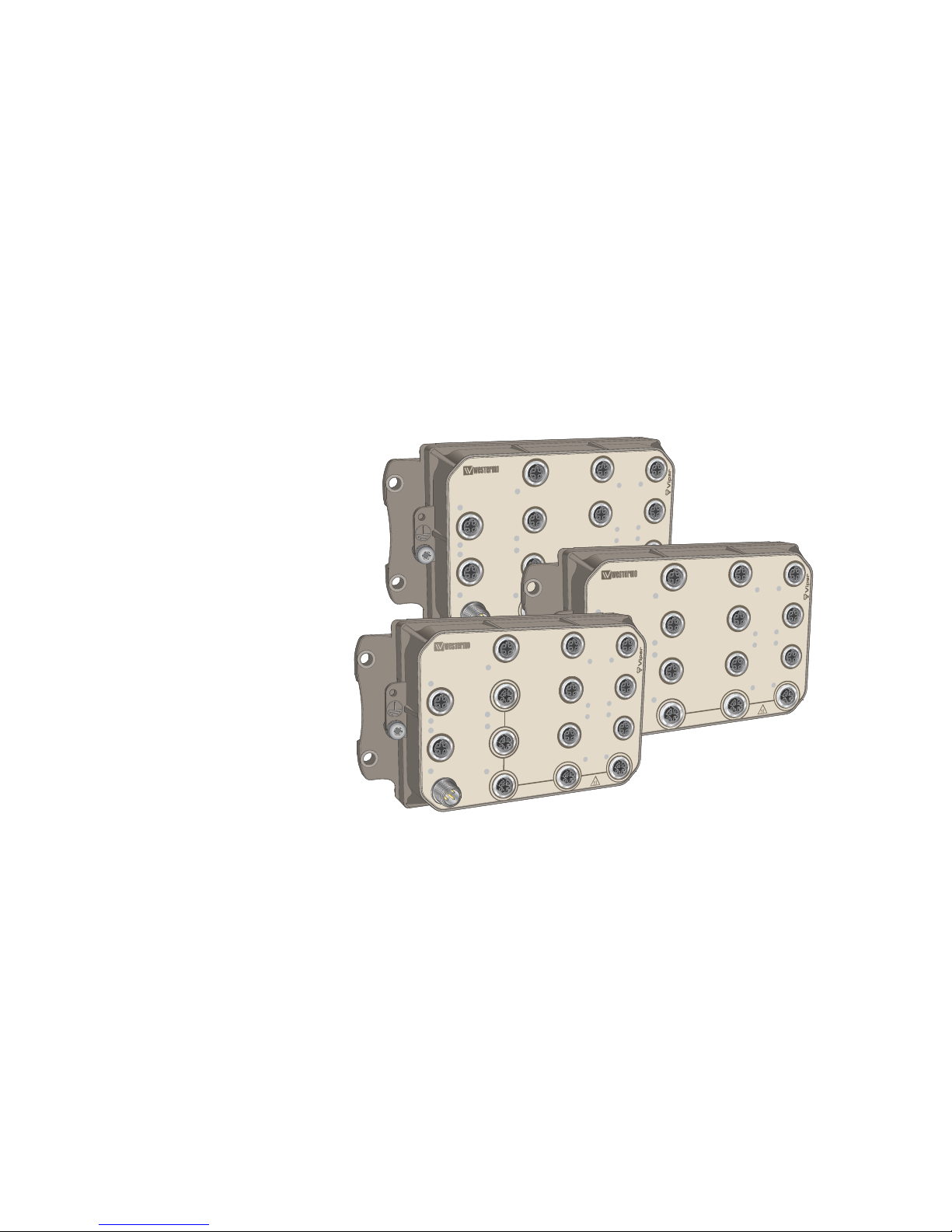
Viper 12A Series
12 port Ethernet M12 switches
Page 2

Table of Contents
1. General Information ........................................................................ 3
1.1. Legal Information ................................................................... 3
1.2. About This Guide ................................................................... 3
1.3. Software Tools ...................................................................... 3
1.4. License and Copyright for Included Free/Libre Open Source
Software .................................................................................... 3
1.5. WeOS Management Guide ...................................................... 3
2. Safety and Regulations ................................................................... 4
2.1. Warning Levels ..................................................................... 4
2.2. Safety Information ................................................................. 5
2.3. Care Recommendations ......................................................... 6
2.4. Maintenance ......................................................................... 6
2.5. Environmental Protection ........................................................ 6
2.6. Compliance Information .......................................................... 7
2.6.1. Agency Approvals and Standards Compliance .................... 7
2.6.2. FCC Part 15.105 Notice ................................................. 7
2.6.3. Declaration of Conformity ............................................... 8
3. Product Description ........................................................................ 9
3.1. Product Description ................................................................ 9
3.2. Available Models ................................................................... 9
3.3. Hardware Overview ............................................................. 10
3.4. Connector Pinout ................................................................. 11
3.5. LED Indicators .................................................................... 13
3.6. Dimensions ........................................................................ 13
4. Installation .................................................................................. 15
4.1. Wall Mounting ..................................................................... 15
4.2. Connection of Cables ........................................................... 15
4.3. Cooling .............................................................................. 16
4.4. Removal of Product ............................................................. 16
4.5. EN 45545-2 Mounting Notes .................................................. 16
5. Specifications .............................................................................. 17
5.1. Interface Specifications ......................................................... 17
5.2. Type Tests and Environmental Conditions ................................. 20
6. Revision Notes ............................................................................ 22
2 Viper 12A Series
Page 3

1. General Information
1.1. Legal Information
The contents of this document are provided “as is”. Except as required by applicable law,
no warranties of any kind are made in relation to the accuracy and reliability or contents of
this document, either expressed or implied, including but not limited to the implied
warranties of merchantability and fitness for a particular purpose. Westermo reserves the
right to revise this document or withdraw it at any time without prior notice.
Under no circumstances shall Westermo be responsible for any loss of data or income or
any special, incidental, and consequential or indirect damages howsoever caused.
More information about Westermo can be found at www.westermo.com.
1.2. About This Guide
This guide is intended for installation engineers and users of the Westermo products.
It includes information on safety and regulations, a product description, installation
instructions and technical specifications.
1.3. Software Tools
Related software tools are available in the folder Software tools under Technical support at
www.westermo.com.
1.4. License and Copyright for Included Free/Libre Open Source
Software
This product includes software developed by third parties, including Free/Libre Open
Source Software (FLOSS). The specific license terms and copyright associated with the
software are included in each software package respectively. Please visit the product web
page for more information.
Upon request, the applicable source code will be provided. A nominal fee may be charged
to cover shipping and media. Please direct any source code request to your normal sales or
support channel.
1.5. WeOS Management Guide
This product runs WeOS (Westermo Operating System). Instructions for quick start,
configuration, factory reset and use of USB port are found in the WeOS Management
Guide at www.westermo.com.
Viper 12A Series 3
Page 4
2. Safety and Regulations
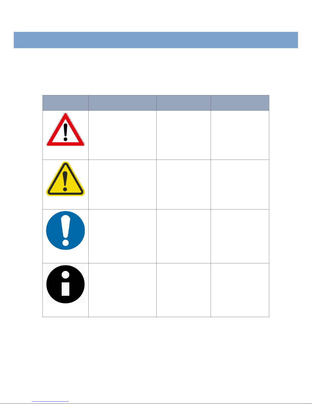
2.1. Warning Levels
Warning signs are provided to prevent personal injuries and/or damages to the product.
The following levels are used:
Level of warning
Description Consequence
personal injury
Consequence
material damage
WARNING
Indicates a potentially
hazardous situation
Possible death or major
injury
Major damage to the
product
CAUTION
Indicates a potentially
hazardous situation
Minor or moderate
injury
Minor damage to the
product
NOTICE
Provides information in order
to avoid misuse of the
product, confusion or
misunderstanding
No personal injury Minor damage to the
product
NOTE
Used for highlighting general,
but important information
No personal injury Minor damage to the
product
Table 1. Warning levels
4 Viper 12A Series
Page 5
2.2. Safety Information
Before installation:
Read this manual completely and gather all information available on the unit. Make sure it is
fully understood. Check that your application does not exceed the safe operating
specifications for this unit.
This unit should only be installed by qualified personnel.
This unit should be built-in to an apparatus cabinet or similar, where access is restricted to
service personnel only.
The power supply wiring must be sufficiently fused, and if necessary, it must be possible to
disconnect it manually from all power supply. Ensure compliance to national installation
regulations.
This unit relies on convection cooling. Make sure that it is installed so that the ambient
temperature is within the specified temperature range, e.g. by avoiding obstruction of the
airflow around the unit. Also see EN 45545-2 Mounting Notes [16] chapter.
WARNING - PREVENT ACCESS TO HAZARDOUS VOLTAGE
Before mounting, using or removing this unit: Prevent access to hazardous
voltage by disconnecting the unit from all power supply.
WARNING - HAZARDOUS VOLTAGE
Do not open the connected unit. Hazardous voltage may occur within this
unit when connected to power supply.
CAUTION - HOT SURFACE
Be aware of that the surface of this unit may become hot. When this unit
is operated at high temperatures, the external surface of the equipment
may exceed Touch Temperature Limit according to EN/IEC/UL 60950-1.
NOTICE - PROTECTIVE EARTHING CONDUCTOR
Before powering-up, a protective earthing conductor must be connected
to the protective earth terminal and have a cross-sectional area of at least
1.5 mm². Note that this unit can be connected to two different power
sources.
Viper 12A Series 5
Page 6
NOTICE - REDUCE RISK OF FIRE
To reduce the risk of fire:
1. Use only No. 21 AWG or larger power cable
2. Use only No. 26 AWG or larger telecommunication line cord
NOTICE - CONNECT EXTERNAL FUSE
The unit has no internal fuse and should be connected via an external
fuse. The fuse should be calculated in accordance with the rated current.
2.3. Care Recommendations
Follow the care recommendations below to maintain full operation of unit and to fulfill the
warranty obligations:
• Do not attempt to dissassemble the unit. There are not any user serviceable parts
inside.
• Do not drop, knock or shake the unit. Rough handling above the specification may cause
damage to internal circuit boards.
• Do not use harsh chemicals, cleaning solvents or strong detergents to clean the unit.
• Do not expose the unit to any kind of liquid (water, beverages, paint etc), unless all
connectors are connected or fitted with protective caps (delivered with the unit),
tightened to the specified torque. Connected cables must have the appropriate ingress
protection code.
• Do not use or store the unit in dusty or dirty areas, unless all connectors and the
ventilation membrane are sufficiently protected.
• Do not cover or bring mechanical force to the ventilation membrane on the back of the
unit.
If the unit is not working properly, contact the place of purchase, nearest Westermo
distributor office or Westermo Tech support.
2.4. Maintenance
No maintenance is required, as long as the unit is used as intended within the specified
conditions.
2.5. Environmental Protection
Waste electrical products should not be disposed of with household waste. Please recycle
where facilities exist. Check with your local authority or retailer for recycling advice.
6 Viper 12A Series
Page 7

2.6. Compliance Information
2.6.1. Agency Approvals and Standards Compliance
Type
Approval/Compliance
Climate • EN 50155/IEC 60571 class TX, Railway applications - Electronic equipment used
on rolling stock
• IEEE 1478 class 1, condition E4 (incl Salt Mist), Environmental conditions for transit
rail car electronic equipment
EMC • EN 61000-6-2, Immunity industrial environments
• EN 61000-6-4, Emission industrial environments
• EN 50121-3-2/IEC 62236-3-2 Railway applications – Rolling stock – apparatus
• Tested and verified for Class S1, DB EMC Regulation 06, Commodity team Radio
compatability in VDB Rev 1.0 (Shunting Radio). Compliant with SBB requirements.
• Tested and verified for Class S1, ÖBB Radio compatability in near field in
accordance with ÖBB Infrastructure Edition 4, Revision 14 (Shunting Radio).
• Tested and verified for FCC part 15
Mechanical
(Shock and
vibration)
• EN 61373 category 1, class B (tested at two times-level)
• EN 60068-2-27 20 g, 11 ms and 100 g, 6 ms
Insulation
(Coordination and
test)
• EN 50124-1, Railway applications – Insulation coordination
• EN 50155/IEC 60571, Railway applications - Electronic equipment used on rolling
stock
Fire protection • EN 45545-2, Fire protection on railway vehicles
• NFPA130, Fire protection for fixed guideway transit and passenger rail system
Table 2. Agency approvals and standards compliance
2.6.2. FCC Part 15.105 Notice
This equipment has been tested and found to comply with the limits for a Class A digital
device, pursuant to Part 15 of the FCC Rules. These limits are designed to provide
reasonable protection against harmful interference when the equipment is operated in a
commercial environment. This equipment generates, uses, and can radiate radio frequency
energy and, if not installed and used in accordance with the instruction manual, may cause
harmful interference to radio communications. Operation of this equipment in a residental
area is likely to cause harmful interference in which case the user will be required to
correct the interference at his own expense.
Viper 12A Series 7
Page 8
2.6.3. Declaration of Conformity
Westermo Teleindustri AB
Declaration of Conformity
Org.nr/
Postadress/Postal address
Tel.
Telefax
Postgiro
Bankgiro
Corp. identity number Registered office
S-640 40 Stora Sundby 016-428000 016-428001 52 72 79-4 5671-5550 556361-2604 Eskilstuna
Sweden Int+46 16428000 Int+46 16428001
The manufacturer Westermo Teleindustri AB
SE-640 40 Stora Sundby, Sweden
Type of product Model1
12-port managed Ethernet M12 Switch Viper-x12A
12-port managed Ethernet M12 Switch with 3Gbps ports Viper-x12A-T3G
12-port managed Ethernet M12 Switch with 5 Gbps ports Viper-x12A-T5G
is in conformity with the following EU directive(s).
No Short name
2014/30/EU Electromagnetic Compatibility (EMC)
2011/65/EU Restriction of the use of certain hazardous substances in electrical and electronic equipment
(RoHS)
References of standards applied for this EU declaration of conformity.
No Title Issue
EN 50121-3-2 Railway applications – Electromagnetic compatibility – Rolling stock -
Apparatus
2015
EN 50121-4 Railway applications – Electromagnetic compatibility – Emission and immunity
of the signaling and telecommunications apparatus
2015
EN 61000-6-2 Electromagnetic compatibility - Generic standards - Immunity for industrial
environments
2005
EN 61000-6-4 Electromagnetic compatibility - Generic standards - Emission standard for
industrial environments
2007
+A1:2011
EN 50581 Technical documentation for the assessment of electrical and electronic products
with respect to the restriction of hazardous substances
2012
1
Model Differences: x = 1 or 2 and indicates Software Class
Pierre Öberg
Technical Manager
10
th
February 2017
8 Viper 12A Series
Page 9

3. Product Description
3.1. Product Description
The Viper-12A series is a series of managed 12 port switches optimised for the needs of
the railway rolling stock market. Gbps ports cope with high bandwidth devices such as
access points and NVRs (Network Video Recorders).
The Viper is designed to withstand the tough environment on-board trains, exposing the
switch to constant vibration, extreme temperatures, humidity and a demanding electrical
environment.
A GORE-TEX® membrane prevents internal condensation. Threading integrated in chassis
provides for additional vibration resistance. High-level isolation between all interfaces
enables direct connectivity to vehicle auxiliary power and protects against overvoltage and
flashover. IP67 protection prevents ingress of water and dust. An overall optimised design
results in an extremely compact package in combination with very high MTBF for easy
integration and low lifecycle cost.
Thorough type testing at independent ISO/IEC 17025 and ILAC MRA certified labs,
accredited to a wide range of standards, show that the Viper series fulfilles EN 50155 and
other requirements. The state-of-the-art Westermo production facility ensures the quality
of each individual unit, e.g. through temperature cycling burn-in testing.
Meeting the requirements of the railcar market, the Viper is very well suited for
deployment in any other application with severe operating conditions and tough
environments, for instance in the mining industry.
3.2. Available Models
All switches are managed. Viper x12A is used when referring to both models 112A and
212A.
Art.no.
Model Layer Gbps ports
3635-0010 Viper-112A 2 -
3635-0020 Viper-212A 3 -
3635-0310 Viper-112A-T3G 2 3
3635-0320 Viper-212A-T3G 3 3
3635-0610 Viper-112A-T5G 2 5
3635-0620 Viper-212A-T5G 3 5
Viper 12A Series 9
Page 10

3.3. Hardware Overview
DC
CON
FRNT
RSTP
ON
X1
X5
X9
X6
X10
X7
X11
X12
X2
X3
X4
X8
24-110 V
DC
M12 Torque 0.6±0,1 Nm / 0,45±0,1 lbft
1000BASE-T
USB
1 2
34
5
7
6
No. Description No. Description
1 LED indicator 2 100 Mbps port
3 Gbps port 4 DC port
5 Console port 6 Protective earth connection
7 USB port
Figure 1. Location of interface ports and LED indicators
10 Viper 12A Series
Page 11

3.4. Connector Pinout
Pin
no.
Signal
Illustration
1 +DC1
2 1
3 4
2 +DC2
3 -COM
4 -COM
Viper-x12A supports redundant power connection.
The positive inputs are +DC1 and +DC2. The
negative input for both supplies is -COM
Table 3. Power connector
Pin no.
Signal Illustration
1 NC
a
2 TX
3 RX
4 NC
a
5 GND
a
No Connect. Do not connect.
Table 4. Console connector
Pin no.
Signal Illustration
1 DN
2 VBUS
3 NC
a
4 DC
5 GND
a
No Connect. Do not connect.
Table 5. USB connector
Viper 12A Series 11
Page 12

Pin
no.
Signal
Illustration
1 TD+
2 RD+
3 TD-
4 RD-
MDI, MDI-X and auto MDI/MDI-X modes are
supported. The table shows signals in MDI mode.
Table 6. 100 Mbps Ethernet connector
Pin no.
Signal Illustration
1 DA+
1
2
3
45
6
7
8
2 DA-
3 DB+
4 DB-
5 DD+
6 DD-
7 DC-
8 DC+
Table 7. Gbps connector
12 Viper 12A Series
Page 13

3.5. LED Indicators
LED Status Description
ON OFF Unit has no power
GREEN All OK, no alarm condition
RED Alarm condition, or until unit has started up.
(Alarm conditions are configurable, see WeOS
Management Guide)
BLINK Location indicator ("Here I am!"). Activated
when connected to WeConfig tool, or upon
request from web or/and CLI. RED BLINK
during boot indicates pending cable factory
reset.
RSTP OFF RSTP disabled
GREEN RSTP enabled
BLINK Unit selected as RSTP/STP root switch
FRNT OFF FRNT disabled
GREEN FRNT OK
RED FRNT error
BLINK Unit configured as FRNT focal point
DC OFF Unit has no power
GREEN Power OK on DC1 and DC2
RED Power failure on DC1 or DC2
X1 to X12 OFF No link
GREEN Link established
GREEN
FLASH
Data traffic indication
YELLOW Port alarm, or port is set in blocking state by
link redundancy protocol
Table 8. LED indicators
3.6. Dimensions
Dimensions are stated in millimetres
Viper 12A Series 13
Page 14

56 ±0,3
164 ± 0,5
100
175
36
65
7,4 ±0,5
Grounding point
screw M5x10
7,2 +0,2 -0,5
Figure 2. Dimensional drawing
14 Viper 12A Series
Page 15

4. Installation
4.1. Wall Mounting
The unit can be wall mounted vertically or horizontally. There are four pieces of 7 mm
bores for this. Use four M5, M6 or 1/4" screws with 12 mm washers on a flat and stable
surface.
DC
CON
FRNT
RSTP
ON
X1
X5
X9
X6
X10
X7
X11
X12
X2
X3
X4
X8
24-110 V
DC
M12 Torque 0.6±0,1 Nm / 0,45±0,1 lbft
1000BASE-T
USB
Figure 3. Wall mounting
4.2. Connection of Cables
Recommended tightening torque for the M12 connectors is 0.6 Nm.
When connecting the power cable, ensure that the pins are connected correctly before
tightening the power cable to the unit.
NOTICE - UNUSED CONNECTORS
Unused connectors must be covered by a protective cap (delivered with
the unit), tightened to the specified torque in order to fulfill the specified
ingress protection code.
Viper 12A Series 15
Page 16

4.3. Cooling
This unit relies on convection cooling. Make sure that it is installed so that the ambient
temperature is within the specified temperature range, e.g. by avoiding obstruction of the
airflow around the unit.
4.4. Removal of Product
Disconnect all cables and unscrew the unit from the wall. Time for replacement: < 10
minutes.
CAUTION - HOT SURFACE
Be aware of that the surface of this unit may become hot. When this unit
is operated at high temperatures, the external surface of the equipment
may exceed Touch Temperature Limit according to EN/IEC/UL 60950-1.
4.5. EN 45545-2 Mounting Notes
Two units can be mounted together and as a single interior non-listed group in the sense of
EN 45545-2 definitions. For multiple units, the spacing requirements for interior non-listed
groups must be met.
16 Viper 12A Series
Page 17

5. Specifications
5.1. Interface Specifications
DC, Power port
Rated voltage 24 to 110 VDC
Operating voltage 16.8 to 143 VDC (14.4 to 154 VDC for 100 ms)
Rated current Max 580 mA at 24 VDC, max 140 mA at 110 VDC
Rated frequency DC
Inrush current, I²t 105 mA²s at 24 VDC, 32 mA²s at 110 VDC
Startup current
a
Max 840 mA at 16.8 VDC
Polarity Reverse polarity protected
Redundant power input Yes
Isolation to 2250 VDC to all other ports
Connector 4-pin, male, M12, A-coded, recommended Westermo cables:
3146-1106 for 1.5 m
3146-1107 for 5 m
Cable size M12, recommended cable area 0.5 mm² (minimum 0.25 mm²)
Cable dimensions depend on choice of M12 connector
a
External supply current capability for proper startup
Viper 12A Series 17
Page 18

100 Mbps ports
a
Electrical specification IEEE std 802.3
Data rate 10 Mbps, 100 Mbps, manual or auto
Duplex Full of half, manual or auto
Circuit type TNV-1
Transmission range Up to 150 m with CAT5e cable or better
Isolation to 2250 VDC, 1 min
b
Connector 4-pin, female, M12, D-coded, auto MDI/MDI-X, recommended Westermo
cables:
3146-1100 M12-M12 - 1 m
3146-1101 M12-M12 - 5 m
3146-1103 RJ45-M12 - 1 m
3146-1104 RJ45-M12 - 5 m
Shielded cable Required
Conductive chassis Yes
FRNT reconfiguration time Typically below 20 ms
a
100 Mbps ports are:
X1-X12 on Viper-x12A
X1-X3, X5-X7, X9-X11 on Viper-x12A-T3G
X1, X5-X7, X9-X11 on Viper-x12A-T5G
b
750 VDC after damp heat, according to EN 50155
Gbps ports
a
Electrical specification IEEE std 802.3
Data rate 10 Mbps, 100 Mbps, 1000 Mbps, manual or auto
Circuit type TNV-1
Transmission range Up to 150 m with CAT5e cable or better
Isolation to 2250 VDC to all other ports
b
Connector 8-pin, female, M12, X-coded
Shielded cable Required
FRNT reconfiguration time Typically below 20 ms
a
Gbps ports are: X4, X8, X12 on Viper-x12A-T3G, X2-X4, X8, X12 on Viper-x12A-T5G
b
750 VDC after damp heat, according to EN 50155
18 Viper 12A Series
Page 19

USB port
Electrical specification USB 2.0 host interface
Data rate Up to 480 Mbps (high-speed mode)
Maximum supply current 500 mA
Circuit type SELV
Isolation to Ethernet and DC ports: 2250 VDC
No isolation to CON or chassis
Connector 5-pin, female, M12, A-coded, recommended Westermo USB plug
3641-0190
Console port
Electrical specification RS-232
Data rate 115.2 kbit/s
Data format 8 data bits, no parity, 1 stop bit, no flow control
Circuit type SELV
Isolation to Ethernet and DC ports: 2250 VDC
No isolation to USB or chassis
Connector 5-pin, female, M12, B-coded, recommended Westermo cables:
1211-2215 (serial port) or 1211-4073 (USB)
Viper 12A Series 19
Page 20

5.2. Type Tests and Environmental Conditions
Environmental
phenomena
Basic
standard
Description
Test levels
ESD EN 61000-4-2 Enclosure Contact: ±6 kV
Air: ±8 kV
Fast transients EN 61000-4-4 Power port ± 2 kV
Signal ports
Earth port
Surge EN 61000-4-5 Power port L-E: ± 2 kV, 42 Ω, 0.5 µF, 1.2/50 µs
L-E: ± 0.5 kV, 12 Ω, 9 µF, 1.2/50 µs
L-L: ± 2 kV, 42 Ω, 0.5 µF, 1.2/50 µs
L-L: ± 0.5 kV, 2 Ω, 18 µF, 1.2/50 µs
Ethernet port L-E: ± 2 kV, 2 Ω
Pulsed magnetic field EN 61000-4-9 Enclosure 300 A/m
Radiated RF
immunity
EN 61000-4-3 Enclosure 20 V/m at (80 MHz to 2 GHz)
10 V/m at (2-6 GHz)
1 kHz sine, 80% AM
Conducted RF
immunity
EN 61000-4-6 Power ports 10 V, 80% AM, 1 kHz; (0.15-80) MHz
Ethernet ports
Earth port
Radiated RF emission CISPR 16-2-3 Enclosure EN 61000-6-4 (30-6000 MHz)
ANSI C63,4
(FCC Part 15)
EN 61000-6-4 (30-6500 MHz)
Conducted RF
emission
CISPR 16-2-1 Power port EN 61000-6-4
Ethernet ports EN 61000-6-3
Dialectric strength EN 60950-1 Power port to all
other ports
2250 VDC, 1 min
Fast Ethernet
ports to all other
ports
2250 VDC, 1 min
a
Gbps Ethernet
ports to all other
ports
2250 VDC, 1 min
a
a
750 VDC after damp heat, according to EN 50155
Table 9. EMC and electrical conditions
20 Viper 12A Series
Page 21

Environmental
phenomena
Basic
standard
Description
Test levels
Temperatures EN 60068-2-1
EN 60068-2-2
Operating -40 to +70°C (-40 to +158°F)
ab
Storage and
transport
-55 to +85°C (-67 to +185°F)
Humidity EN 60068-2-30 Operating 5-95% relative humidity
Storage and
transport
Altitude Operating 2000 m/70 kPa
Service life Operating 20 years according to IEC/TR 62380
MTBF
Viper-x12A:
1: 557,000 hours
1: MIL-C217F2, GB, 25°C (+77°F)
2: IEC 62380
Viper-x12A-T3G:
1: 549,000 hours
2: 561,000 hours
Viper-x12A-T5G:
1: 544,000 hours
Vibration IEC 60068-2-6
(sine)
Operational 2 g rms 5-500 Hz, 5 sweeps
IEC
60068-2-64
(random)
Non-operational
long life
simulation
11.44 m/s² rms 5-150 Hz, 5 hours
2.3 m/s² rms 5-2000 Hz, 5 hours
Shock IEC
60068-2-27
Operational 10 g, 30 ms, half sine
20 g, 11 ms, saw tooth
100 g, 6 ms, half sine
Enclosure EN 60950-1 Zinc (front),
Aluminium (rear)
Fire enclosure
Dimension WxHxD
with connectors
See "Dimensions" chapter for details
Weight 1.4 kg
Degree of protection EN 60529 Enclosure IP67
c
Cooling Convection
a
Refer to "Safety and Regulations" chapter regarding touch temperature
b
Operational at +85°C for a limited time
c
Provided all connectors are connected with IP67 cabling or fitted with protective caps (delivered with the unit)
and tightened to the specified torque.
Table 10. Environmental and mechanical conditions
Viper 12A Series 21
Page 22

6. Revision Notes
Revision
Date Change description
Rev. D 2017-07 New layout for user guide with rearranged chapters, chapter 1 has
updated texts and new chapter 1.5, new defining Warning levels in chapter
2.1, 2.6.1 Agency approvals updated (Shock and NFPA 130), updated text
in chapter 3.1, "±" removed from "±2250 VDC" throughout the user
guide, radiated RF immunity, service life, shock and operating temperature
updated in chapter 5.2
Old chapters Getting started, Configuration, Reference documents and
Cable factory reset are deleted.
Rev. E 2017-09 2.1. Definition of personal injury at Caution level updated, 2.6.1
Mechanical data updated, 3.6 Dimensional drawing updated, 5.1
Transmission range for 100 Mbps ports and Gbps por ts changed to 150
m, 5.2 Enclosure updated, Radiated + Conducted RF emission updated
22 Viper 12A Series
Page 23

23 Viper 12A Series
Page 24

For complete contact information, please visit our website at www.westermo.com/contact or scan the QR code
Australia
info@westermo.net.au
www.westermo.net.au
China
sales.cn@westermo.com
cn.westermo.com
Finland
tiedot@westermo.fi
www.westermo.fi
France
infos@westermo.fr
www.westermo.fr
Germany
info@westermo.de
www.westermo.de
North America
info@westermo.us
www.westermo.us
Singapore
sales@westermo.com.sg
www.westermo.com.sg
Sweden
info.sverige@westermo.se
www.westermo.se
United Kingdom
sales@westermo.co.uk
www.westermo.co.uk
Other Offices
Sales Units
Westermo Data Communications
Westermo • SE-640 40 Stora Sundby, Sweden
Tel +46 16 42 80 00 Fax +46 16 42 80 01
E-mail: info@westermo.com
www.westermo.com
6641-22511 REV. E 2017 09 Westermo Teleindustri AB, Sweden
 Loading...