

Page 1
User Guide
6651-22651
ODW-630-F2
Fibre Optic Modem
Westermo Teleindustri AB
©
Industrial Converter
RS-485 to Fibre Optic Link
Repeater, line and redundant ring
www.westermo.com
Page 2

2
6651-22651
Legal information
The contents of this document are provided “as is”. Except as required by applicable
law, no warranties of any kind, either express or implied, including, but not limited to,
the implied warranties of merchantability and fitness for a particular purpose, are made
in relation to the accuracy and reliability or contents of this document. Westermo
reserves the right to revise this document or withdraw it at any time without prior
notice.
Under no circumstances shall Westermo be responsible for any loss of data or income
or any special, incidental, and consequential or indirect damages howsoever caused.
More information about Westermo can be found at the following Internet address:
http://www.westermo.com
Page 3

3
6651-22651
Safety
!
!
!
Before installation:
Read this manual completely and gather all information on the unit. Make sure
that you understand it fully. Check that your application does not exceed the safe
operating specifications for this unit.
This unit should only be installed by qualified personnel.
This unit should be built-in to an apparatus cabinet, or similar, where access is
restricted to service personnel only.
The power supply wiring must be sufficiently fused, and if necessary it must be
possible to disconnect manually from the power supply. Ensure compliance to
national installation regulations.
This unit uses convection cooling. To avoid obstructing the airflow around the unit,
follow the spacing recommendations (see Cooling section).
Before mounting, using or removing this unit:
Prevent access to hazardous voltages by disconnecting the unit from the power
supply.
Warning! Do not open a connected unit. Hazardous voltages may occur within
this unit when connected to a power supply.
Class 1 Laser Product
This unit is designed to meet the Class 1 Laser regulations. However, the user is
warned not to look directly into fibre optical port or any connected fibre.
Care recommendations
Follow the care recommendations below to maintain full operation of the unit and to
fulfil the warranty obligations.
This unit must not be operated with covers or lids removed.
Do not attempt to disassemble the unit. There are no user serviceable parts inside.
Do not drop, knock or shake the unit. Rough handling beyond the specification may cause
damage to internal circuit boards.
Do not use harsh chemicals, cleaning solvents or strong detergents to clean the unit.
Do not paint the unit. Paint can clog the unit and prevent proper operation.
Do not expose the unit to any kind of liquids (rain, beverages, etc).
The unit is not waterproof. Keep the unit within the specified humidity levels.
Do not use or store the unit in dusty, dirty areas. Connectors as well as other
mechanical parts may be damaged.
If the unit is not working properly, contact the place of purchase, nearest Westermo
distributor office, or Westermo Tech support.
Fibre connectors are supplied with plugs to avoid contamination inside the optical port.
The plug should be fitted when no optical fibre is inserted in the connector, e.g. during
storage, service or transportation.
Page 4

4
6651-22651
Note. Fibre Optic Handling
Fibre optic equipment requires careful handling as the fibre components are very
sensitive to dust and dirt. If the fibre is disconnected from the modem, the protective
plug on the transmitter/receiver must be replaced. The protective plug must be kept on
during transportation. The fibre optic cable must also be protected in the same way.
If this recommendation is not followed, it can jeopardise the warranty.
Cleaning of the optical connectors
In the event of contamination, the optical connectors should be cleaned by using forced
nitrogen and some kind of cleaning stick.
Recommended cleaning fluids:
• Methyl-, ethyl-, isopropyl- or isobutyl-alcohol
• Hexane
• Naphtha
Maintenance
No maintenance is required, as long as the unit is used as intended within the specified
conditions.
Agency approvals and standards compliance
Type Approval / Compliance
EMC EN 61000-6-1, Immunity residential environments
EN 61000-6-2, Immunity industrial environments
EN 61000-6-3, Emission residential environments
EN 61000-6-4, Emission industrial environments
EN 55022, Emission IT equipment, class A
EN 55024, Immunity IT equipment
FCC part 15 Class A
EN 50121-4, Railway signalling and telecommunications apparatus
IEC 62236-4, Railway signalling and telecommunications apparatus
Safety EN 60950-1, IT equipment
FCC Part 15.105
Notice:
EN 55022 Notice:
This equipment has been tested and found to comply with the limits for a Class A
digital device, pursuant to Part 15 of the FCC Rules. These limits are designed to provide
reasonable protection against harmful interference when the equipment is operated in a
commercial environment.
This equipment generates, uses, and can radiate radio frequency energy and, if not
installed and used in accordance with the instruction manual, may cause harmful interference to radio communications. Operation of this equipment in a residential area is likely
to cause harmful interference in which case the user will be required to correct the
interference at his own expense.
This is a class A product. In a domestic environment this product may cause radio interference in which case the user may be required to take adequate measures.
Page 5
5
6651-22651
Declaration of Conformity
Westermo T eleindustri AB
Declaration of conformity
Org.nr/
Postadress/Postal address
Tel.
Telefax
Postgiro
Bankgiro Corp. identity number Registered office
S-640 40 Stora Sundby 016-428000 016-428001 52 72 79-4 5671-5550 556361-2604 Eskilstuna
Sweden I nt+46 16428000 Int+46 16428001
The manufacturer Westermo Teleindustri AB
SE-640 40 Stora Sundby, Sweden
Herewith declares that the product(s)
Type of product Model Art no
Industrial fiberoptic repeaters/media
converters
ODW-600 series 3651-0xxx
ODW-600 series 3650-0xxx
is in conformity with the following EC directive(s).
No Short name
2004/108/EC Electromagnetic Compatibility (EMC)
2011/65/EU Restriction of the use of certain hazardous substances in electrical and
electronic equipment (RoHS)
References of standards applied for this EC declaration of conformity.
No Title Issue
EN 50121-4 Railway applications – Electromagnetic compatibility – Emission and
immunity of the signalling and telecommunications apparatus
2006
EN 55022 Information technology equipment – Radio disturbance characteristics –
Limits and methods of measurement
2006
+A1:2007
EN 55024 Information technology equipment – Immunity characteristics
Limits and methods of measurement
1998
+A1:2001
+A2:2003
EN 61000-6-1 Electromagnetic compatibility – Immunity for residential environments 2007
EN 61000-6-2 Electromagnetic compatibility – Immunity for industrial environments 2005
EN 61000-6-3 Electromagnetic compatibility – Emission residential environments 2007
EN 61000-6-4 Electromagnetic compatibility – Emission for industrial environments 2007
The last two digits of the year in which the CE marking was affixed: 12
Pierre Öberg
Technical Manager
18th December 2012
Page 6

6
6651-22651
Type tests and environmental conditions
Electromagnetic Compatibility
Phenomena Test Description Level
ESD EN 61000-4-2 Enclosure contact ± 6 kV
RF field AM modulated IEC 61000-4-3 Enclosure 10 V/m 80% AM (1 kHz), 80 – 800 MHz
RF field 900 MHz ENV 50204 Enclosure 20 V/m pulse modulated 200 Hz, 900 ± 5 MHz
Fast transient EN 61000-4-4 Signal ports ± 2 kV
Surge EN 61000-4-5 Signal ports unbalanced ± 2 kV line to earth, ± 2 kV line to line
RF conducted EN 61000-4-6 Signal ports 10 V 80% AM (1 kHz), 0.15 – 80 MHz
Pulse Magnetic field EN 61000-4-9 Enclosure 300 A/m, 6.4 / 16 µs pulse
Voltage dips
and interruption
Mains freq. 50 Hz EN 61000-4-16 Signal ports 100 V 50 Hz line to earth
Mains freq. 50 Hz SS 436 15 03 Signal ports 250 V 50 Hz line to line
Radiated emission EN 55022 Enclosure Class B
Conducted emission EN 55022 AC power ports Class B
Dielectric strength EN 60950 Signal port to all other
Environmental
Temperature Operating –40 to +60°C
Humidity Operating 5 to 95% relative humidity
Altitude Operating 2 000 m / 70 kPa
Service life Operating 10 year
Vibration IEC 60068-2-6 Operating 7.5 mm, 5 – 8 Hz
Shock IEC 60068-2-27 Operating 15 g, 11 ms
Packaging
Enclosure UL 94 PC / ABS Flammability class V-1
Dimension W x H x D 35 x 121 x 119 mm
Weight 0.26 kg
Degree of protection IP 21
Cooling IEC 529 Enclosure Convection
Mounting Horizontal on 35 mm DIN-rail
EN 61000-4-11 AC power ports 10 & 5 000 ms, interruption
FCC part 15 Class A
FCC part 15 AC power ports Class B
EN 55022 DC power ports Class A
Enclosure air ± 8 kV
20 V/m 80% AM (1 kHz), 800 – 1000 MHz
20 V/m 80% AM (1 kHz), 1400 – 2700 MHz
Power ports ± 2 kV
Signal ports balanced ± 2 kV line to earth, ± 1 kV line to line
Power ports ± 2 kV line to earth, ± 2 kV line to line
Power ports 10 V 80% AM (1 kHz), 0.15 – 80 MHz
200 ms, 40% residual voltage
500 ms, 70% residual voltage
isolated ports
Power port to other
isolated ports
Storage & Transport –40 to +70°C
Maximum surface
temperature
Storage & Transport 5 to 95% relative humidity
2 kVrms 50 Hz 1min
3 kVrms 50 Hz 1min
2 kVrms 50 Hz 1min (@ rated power < 60V)
135ºC (temperature class T4)
2 g, 8 – 500 Hz
Page 7
7
6651-22651
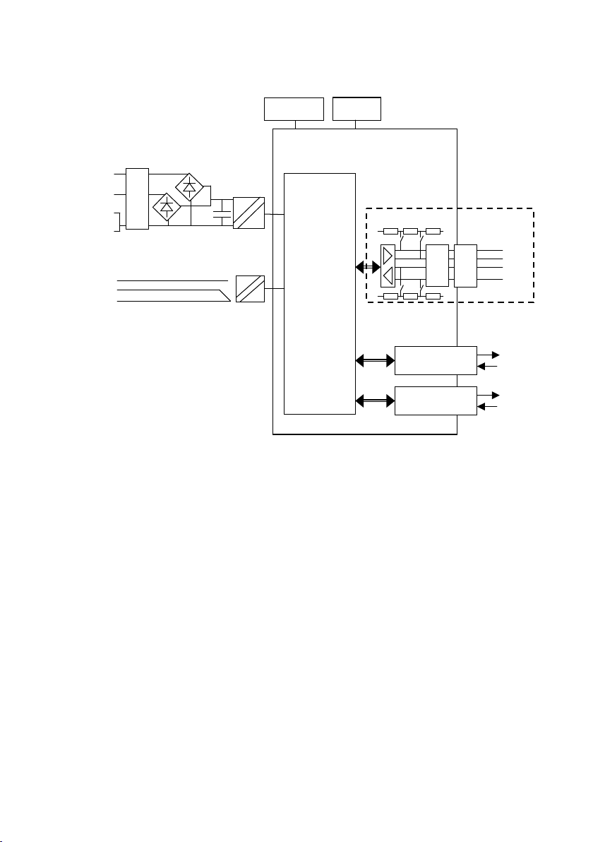
STATUS
C
NO
NC
LED’s
Switches
CH 2
SFP
Fibre transceiver
TX
RX
CH 1
SFP
Fibre transceiver
TX
RX
Internal
Electronics
ODW-630F2
COM
COM
+VA
O
V
P
+VB
POWER
T/R
-
RS -485
R
-
+5V
0V
+5V
0V
O
C
P
O
V
P
Functional description
OVP Over Voltage Protection
OCP Over Current Protection
Converter serial interface – optical fibre
ODW-630-F2 is a fibre optic modem that converts between electrical RS-485 and a fibre
optical link.
ODW-630-F2 can also be used to convert from RS-232 to RS-485 by using a
ODW-620-F2 and ODW-630-F2.
Repeater – optical fibre links
ODW-630-F2 is a fibre optic repeater that repeats received data from one fibre link out
to the other link. This is useful e.g. for long distance communication, where electromagnetic interference may occur or when isolation of the electrical network is needed. The
maximum optical fibre distance depends on selected fibre transceiver and fibre type.
Data rate up to 1.5 Mbit/s
ODW-630-F2 converts data using rates from 300 bit/s up to 1.5 Mbit/s. Retiming
of the data ensures that the correct signal form is transmitted from the ODW-630-F2
converter.
Page 8
8
6651-22651
Designed for harsh environments, such as industrial,
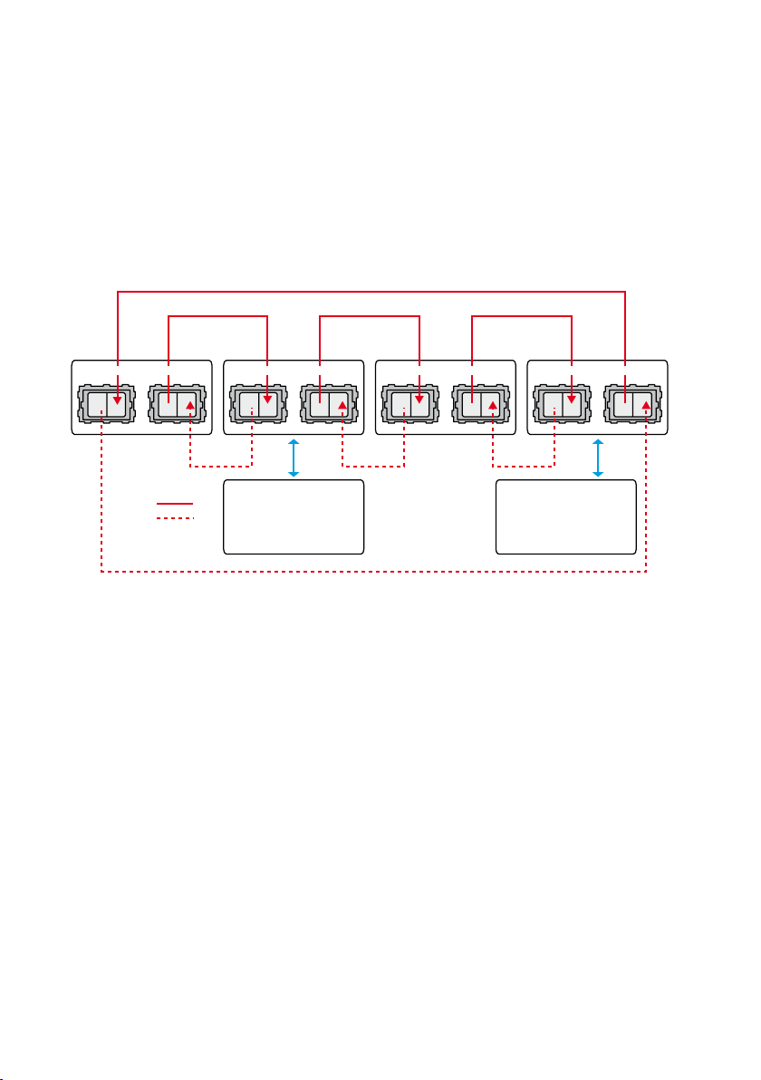
TX RX TX RX TX RX TX RX TX RX TX RX TX RX TX RX
Master, unit Slave, unit
CH 2 CH 1 CH 2 CH 1 CH 2 CH 1 CH 2 CH 1
Ring A
Ring B
MS
PLC PLC
road and railway applications
ODW-630-F2 complies with standards for industrial environments and railway
signalling and telecommunications apparatus. Additionally, the wide climatic range
of the ODW-630-F2 allows it to be installed in out-door cabinets without any
additional measures, such as heating, etc.
Redundant ring via fibre optical network
Under normal operation the serial data is sent over ring A. Should a fault be detected on
the fibre ring then the data will be carried on rings A and B.
Ring A
Ring A Ring A Ring A
Ring B Ring B Ring B
Ring B
Note! Ring A start up at TX (channel 1) and ring B ends up at RX (channel 1).
… Normal operation, data exchange between serial master and slave.
• ODW-630-F2 unit connected to the PLC-master receives serial data at the electrical
port, it converts and transfers this master frame via the fibre ring A. At this unit the
repeating of transferred frames is stopped until this transferred master frame has
returned via ring A.
This master frame will be repeated through fibre ring A by all the other units. Each
of these units will also convert the master frame to serial data and send it via the
electrical port.
• ODW-630-F2 unit to which the addressed Slave is connected, receives serial data
from the Slave. This unit converts slave data and transfers the slave frame via ring A.
The repeating of transferred frames is stopped until this transferred slave frame has
returned via ring A.
• When the “first” ODW-630-F2 unit receives the master frame (the same frame
that has been transmitted by this unit), or after a timeout, data conversion at will
be allowed again. The received slave frame will be converted and transmitted at the
electrical port.
Page 9

9
6651-22651
• When the ODW-630-F2 unit connected to the PLC slave receives the slave frame
(the same frame that has been transmitted by this unit), or after a timeout, data
conversion at this unit will be allowed again.
… Behaviour under faulty conditions
• Elapsed time from any kind of failure at the fibre optic network until data exchange
after a corrective action depends on total length of fibre ring.
This is typically 40–500 ms (local unit). During that time, the transferred data frames
should be seen as corrupted or missed.
Note: Be ware of that full duplex will not work in redundant ring.
Failure Indications
Fibre interruption ring A, TX On: FL R
Fibre interruption ring A, RX On: FL L
Fibre interruption ring A, RX & TX On FL L
Fibre interruption ring B, TX On: FL R
Fibre interruption ring B, RX On: FL L
Fibre interruption ring B, RX & TX On: FL L
Fibre interruption ring A and B (e.g. CH1 or CH2 both TX & RX) On: FL L &/or FL R
Low power on the receiver
(May indicate bad fibre)
* Regarding functionality see chapter “multidrop application”
FLL flicker
… Recovery from faulty status
• ODW-630-F2 will automatically recover to the previous operating status when a
failure disappears. This involves recovery from multi drop application to Redundant
ring A/B when ring is up and running and recovery from Ring B to Redundant ring A
when the ring is up and running.
• The time to recover from the failure status depends on total length of fibre ring.
This is typically 40–500 ms. During that time the transferred data frames should be
seen as corrupted or missed.
Serial data transfer can be set in two modes:
Synchronous mode: Transfer special protocols such as Manchester coded protocol.
See special switch settings on page 20.
Asynchronous mode: Data will be sent over the fibre optic network when a startbit
has been identified. The data rate and number of data bits should be set by DIP-switches.
the turning time (from sending serial RS-485 data until changing to receive mode) is
automatically calculated from the DIP-switch setting.
Page 10

10
6651-22651
Multidrop via fibre optical network
TX RX TX RX TX RX TX RX TX RX TX RX TX RX TX RX
CH 2 CH 1 CH 2 CH 1
Master, unit
M
Slave, unit
S
CH 2 CH 1 CH 2 CH 1
PLC PLC
The data is transferred via the fibre optic network to the serial ports of all units. If
ODW-630-F2 is connected to two optical fibre links (mid unit) converted data will be
transmitted in both directions, via both CH 1 and CH 2. With only one optical fibre link
(end unit) converted data will be transmitted in one direction, via CH 1 only.
Data received from one ODW-630-F2 optical fibre port will be repeated through the
other optical fibre port and it will also convert the frame to serial data.
Page 11

11
6651-22651
Optical fibre link functionality and status indication
At power on, all LED’s will be active during an initiation sequence followed by an automatic initiation of the optical fibre links. The alarm will be set until the fibre optical links
are in operation and ready to transfer serial data.
Data frames are transferred over the fibre optic links as long as the links are in operation
and the data rate has been detected.
When any of the fibre optic links is out of operation, this will be indicated by a local
alarm, and this will set the alarm output. It will also send a remote alarm via the other
link, if possible. When the link returns to operations mode, the alarm will reset automatically.
RS-485 interface
A 4 position detachable screw terminal that can handle full duplex data rates up to
1.5 Mbit/s and can be set to either 2- or 4-wire RS-485 system.
When 4-wire RS-485 is selected, the terminals T/R+ and T/R– will always be set to
transmit and terminals R+ and R– will always receive data.
Manchester coded protocol can be transferred with Synchronous mode.
Redundant power supply, galvanic isolated (2 kVAC) to other ports
ODW-630-F2 should be supplied with safety extra low voltage (SELV). It is designed to
operate permanently over a wide input range and provided with two independent inputs,
allowing redundancy should either supply fail.
Single- or multimode LC fibre connectors
ODW-630-F2 use Small Form Factor Pluggable (SFP) transceivers that are in compliance
with the Multi-Sourcing Agreement (MSA). This means that a wide range of different fibre
transceivers and connectors can be used.
Status interface
This port enables supervision of fibre optic link status by a relay with both normally open
and closed contacts.
The status will be set if:
• Local or remote of fibre link errors exist.
• The unit is out of service, e.g. no power supply.
Page 12

12
6651-22651
System delay in an optical network
Data exchange between a serial master and slave via ODW-630-F2 fibre optic link,
will be delayed due to the length of the optical fibre and the signal processing within
the ODW-630-F2. The signal processing delay is dependent on the data rate, and the
fibre delay is dependent on the total length of the optical fibre.
There is no limitation of the total length of optical fibre for Multi-drop applications. In
Redundant ring applications the data transfer time in a ring is limited to 10 milliseconds.
This means the total length of the optical fibre ring is about 2 000 km, excluding the
1 microsecond delay at each optical repeater unit.
The additional time resulting from the optical fibre and ODW-630-F2 is the Overall
system delay. The Redundant ring and Multidrop application Overall system delays
differ, see below.
Item Functions Delay
1 Fibre:
Optical fibre length delay (typical)
2 Converter electrical to fibre:
Signal processing
3 Converter fibre to electrical:
Signal processing
Note t
… Redundant ring, one data exchange.
= 1 / Baud rate (Baud rate in bit/s)
bit
• The data exchange between master and slave via ODW-630-F2 fibre optic link will run one
direction through all units of the ring. The system delay is calculated by summing the following:
1. Fibre: The total optical fibre ring length delay.
2. Optical repeaters: The optical repeater delay x Number of optical repeaters (excluding the
ODW-630-F2 units connected to a master and addressed slave).
3. Converter electrical to fibre: Signal processing delay x 2
(ODW-630-F2 units connected to serial master and addressed slave).
4. Converter fibre to electrical: Signal processing delay x 2 (ODW-630-F2 units connected
to a master and addressed slave).
5 ms/km
0.6 ms (synchronous mode)
+ 0.6 ms
1 t
Bit
(asynchronous mode)
0.6 ms
Multi drop, one data exchange.
• The data exchange between a master and slave via ODW-630-F2 fibre optic link will run from
the ODW-630-F2 units connected to a master to the slave and the same way back to the master.
The system delay is calculated by summing the following:
1. Fibre: The optical fibre length a master to addressed slave delay x 2.
2. Optical repeaters: The optical repeater delay * Number of optical repeaters
(excluding the ODW-630-F2 units connected to a master and addressed slave) x 2.
3. Converter electrical to fibre: Signal processing delay x 2
(ODW-630-F2 units connected to a master and addressed slave).
4. Converter fibre to electrical: Signal processing delay x 2
(ODW-630-F2 units connected to a master and addressed slave).
Page 13

13
6651-22651
Example
• Redundant ring, one data exchange between master and one slave.
One a master and 11 slaves with data rate 9600 bit/s dependent mode.
12 ODW-630-F2 units with a total fibre length of 40 km. A data exchange
between master and one slave.
1. Fibre: The total optical fibre ring length delay.
40 x 5 µs = 200 µs
2. Optical repeaters:
The optical repeater delay x Number of optical repeaters
(excluded the two units connected to PLC master and slave).
10 x 3.0 µs = 30 µs
3. Converter electrical to fibre:
Signal processing delay x 2
(ODW-630-F2 units connected to a master and addressed slave).
+ 0.6 µs) x 2 = (105 µs + 0.6 µs) x2 = 211 µs
(1 t
bit
4. Converter fibre to electrical:
Signal processing delay x 2
(units connected to PLC master and slave).
0.6 µs x 2 = 1.2 µs
5. The system delay is calculated by summing the delays in item 1 to 4 above:
200 µs + 30 µs + 211 µs + 1.2 µs = 442 µs
Page 14

14
6651-22651
Interface specifications
Power
Rated voltage 12 to 48 VDC
Operating voltage 10 to 60 VDC
Rated current 400 mA @ 12 V
Rated frequency DC: –
Inrush current I²t 0.2 A²s
Startup current* 1.0 Apeak
Polarity Reverse polarity protected
Redundant power input Yes
Isolation to RS-422/485 and Status port
Connection Detachable screw terminal
Connector size 0.2 – 2.5 mm² (AWG 24 – 12)
Shielded cable Not required
* External supply current capability for proper startup
RS-422/485
Electrical specification EIA RS-485, 2-wire or 4-wire twisted pair
Data rate 300 bit/s – 1.5 Mbit/s
Data format 9 – 12 bits
Protocol Start-bit followed by 8-11 bits
Retiming Yes
Turning time
(2-wire RS-485)
Transmission range < 1200 m, depending on data rate and cable type (EIA RS-485)
Settings 120 W termination and failsafe biasing 680 W
Protection Installation Fault Tolerant (up to ±60 V)
Isolation to Status and Power port
Connection Detachable screw terminal
Connector size 0.2 – 2.5 mm² (AWG 24 – 12)
Shielded cable Not required
24 VAC
20 to 30 VAC
250 mA @ 24 V
100 mA @ 48 V
AC: 48 to 62 Hz
One t
bit
= 1 / Baud rate (Baud rate in bit/s)
t
bit
Status
Port type Signal relay, changeover contacts
Rated voltage Up to 48 VDC
Operating voltage Up to 60 VDC
Contact rating 500 mA @ 48 VDC
Contact resistance < 50 mW
Isolation to RS-422/485 and Power port
Connection Detachable screw terminal
2
Connector size 0.2 – 2.5 mm
(AWG 24 – 12)
Shielded cable Not required
Page 15

15
6651-22651
Optical Power Budget
The allowed link length is calculated from the optical power budget (OPB), the available optical
power for a fibre-optic link, and the attenuation of the fibre, comprising losses due to in-line
connectors, splices, optical switches and a margin for link ageing (typical 1.5 dB for 1300 nm).
The worst-case optical power budget (OPB) in dB for a fibre-optic link is determined by the difference between the transmitter’s output optical power (min) and the receiver input sensitivity (max).
FX (Fibre) SM-LC80 SM-LC40 SM-LC15 MM-LC2
Fibre connector LC duplex LC duplex LC duplex LC duplex
Fibre type Singlemode
9/125 mm
Singlemode
9/125 mm
Singlemode
9/125 mm
Multimode,
62.5/125 and
50/125 mm
Wavelength 1550 nm 1310 nm 1310 nm 1310 nm
Transmitter
–5/0 dBm** –5/0 dBm** –15/–8 dBm** –20/–14 dBm*
Output optical power min/max
Receiver
–34 dBm –34 dBm –31 dBm –31 dBm
Input sensitivity, max
Receiver
–5 dBm*** –3 dBm*** –8 dBm –8 dBm
Input optical power, max
Optical power budget,
29 dB 29 dB 16 dB 11 dB
worst-case
Transceiver type Small Form Factor Pluggable (SFP)
Multi-Sourcing Agreement (MSA) compliant
Laser class Class 1, IEC 825-1 Accessible Emission Limit (AEL)
FX (Fibre)
Bi-di
LC-60
Bi-di
LC-40
Bi-di
LC-20
Bi-di
MM LC-2
Fibre connector LC Simplex LC Simplex LC Simplex LC Simplex
Fibre type Singlemode
9/125 µm
Singlemode
9/125 µm
Singlemode
9/125 µm
Multimode
62.5/125 and
50/125 µm
Wavelength nm, connector 1
Wavelength nm, connector 2
Transmitter
Tx 1310, rx
1550 Tx 1550,
rx 1310
Tx 1310, rx
1550 Tx 1550,
rx 1310
Tx1310, rx
1550 TX
1550, rx 1310
Tx 1310, rx
1550 Tx 1550,
rx 1310
–5/0 dBm ** –8/0 dBm ** -10/0 dBm ** –10/–8 dBm *
Output optical power min/max
Receiver
–34 dBm –34 dBm –28 dBm –28 dBm
Input sensitivity, max
Receiver
0 dBm*** 0 dBm*** 0 dBm –0 dBm
Input optical power, max
Optical power budget,
29 dB 26 dB 18 dB 18 dB
worst-case
Transceiver type Small Form Factor Pluggable (SFP)
Multi-Sourcing Agreement (MSA) compliant
Laser class Class 1, IEC 825-1 Accessible Emission Limit (AEL)
* Output power is power coupled into a 62.5/125 mm multimode fibre
** Output power is power coupled into a 9/125 mm singlemode fibre
*** The optical power should be reduced by at least 5 dB (SM-LC80 and Bi-di LC-60) or 3dB (SM-LC-40
and Bi-di LC-40) between the optical output and input.
Page 16

16
6651-22651
Location of Interface ports, LED’s and DIP-switches
LED Indicators(for details see page 17)
FX(Fibre)
(for details
see page 15)
DIP-switches accessible under lid
(for details see page 18-20)
Status
screw terminal
Position Direction* Description Product
Contact with C
1 NO
when fibre optical
links are in operation
2 C Common C
Open (no contact
3 NC
with C) when fibre
optical links are in
operation
marking
NO
NC
RS-422/485
screw terminal
Position Direction* Description Product
1 In R+ (EIA RS-485 A’) R+
2 In R– (EIA RS-485 B’) R–
3 In/Out T+ (EIA RS-485 A) T/R+
4 In/Out T– (EIA RS-485 B) T/R–
marking
Power
screw terminal
Position Direction* Description Product
1 In Common voltage COM
2 In Voltage A +VA
3 In Voltage B +VB
4 In Common voltage COM
* Direction relative this unit
marking
Page 17

17
6651-22651
LED indicators
LED Status Description
PWR
Power
RDR ON Redundant ring mode
CH 2 ON Fiber link at port CH 2 in operation.
CH 1 ON Fibre link at port CH 1 in operation.
TD
Serial data Receive
RD
Fibre link data Receive
FL R (Red)
Failure Link Remote
FL L (Red)
Failure Link Local
ON In service (power)
Flashing Fault condition
OFF Out of service
OFF Multidrop mode
Data can be transmitted
OFF Fiber link at port CH 2 out of operation
Data can be transmitted
OFF Fibre link at port CH 1 out of operation
Flashing Receive accepted data on the serial port.
Data will be transmitted to the fibre link
OFF –
Flashing Received data on the fibre link. This
frame is transmitted to the serial port.
OFF –
ON Remote fibre link failure. A fibre link is
out of operation at any other unit of the
optical network
OFF All fibre links are in operation at all
other units in the fibre optical network
ON Local fibre link failure. This unit has
identified a fibre link failure
OFF Fibre link of this unit is in operation
Page 18

18
6651-22651
Configuration
!
All needed configurations and parameter settings are done by the DIP-switches, located
under the top lid.
S2S1
S3
DIP-switch settings
Before DIP-switch settings:
Prevent damage to internal electronics from electrostatic discharges (ESD) by
discharging your body to a grounding point (e.g. use of wrist strap)
Note: Disconnect power before DIP-switch settings.
S1 DIP-switch, asynchronous mode
ON
1 2 3 4 5 6 7 8
ON
1 2 3 4 5 6 7 8
ON
1 2 3 4 5 6 7 8
ON
1 2 3 4 5 6 7 8
ON
1 2 3 4 5 6 7 8
ON
1 2 3 4 5 6 7 8
ON
1 2 3 4 5 6 7 8
ON
1 2 3 4 5 6 7 8
ON
1 2 3 4 5 6 7 8
RS-485 2-wire
RS-485 4-wire
300 bit/s
1 200 bit/s
2 400 bit/s
4 800 bit/s
9 600 bit/s
19.2 kbit/s
38.4 kbit/s
ON
1 2 3 4 5 6 7 8
ON
1 2 3 4 5 6 7 8
ON
1 2 3 4 5 6 7 8
ON
1 2 3 4 5 6 7 8
ON
1 2 3 4 5 6 7 8
ON
1 2 3 4 5 6 7 8
ON
1 2 3 4 5 6 7 8
ON
1 2 3 4 5 6 7 8
ON
1 2 3 4 5 6 7 8
57.6 kbit/s
115.2 kbit/s
125 kbit/s
187.5 kbit/s
230.4 kbit/s
250 kbit/s
500 kbit/s
1.0 Mbit/s
1.5 Mbit/s
Page 19

19
6651-22651
S1 DIP-switch
ON
1 2 3 4 5 6 7 8
ON
1 2 3 4 5 6 7 8
9 bits data format
10 bits data format
ON
1 2 3 4 5 6 7 8
ON
1 2 3 4 5 6 7 8
11 bits data format
12 bits data format
S2 DIP-switch
ON
1 2 3 4 5 6 7 8
ON
1 2 3 4 5 6 7 8
ON
1 2 3 4 5 6 7 8
Multidrop- end unit
(Use channel 1 for end unit)
Multidrop, Mid unit .
Redundant ring
* SW 2:6 ON: The status relay only change status in the unit that is connected to the receive side.
ON
1 2 3 4 5 6 7 8
ON
1 2 3 4 5 6 7 8
Set status interface at local fibre
link error*
Synchronous mode
(see table on next page)
S3 DIP-switch
ON
No termination and fail-safe
1 2 3 4
ON
Termination with fail-safe (4-wire)
1 2 3 4
ON
Termination with fail-safe (2-wire)
1 2 3 4
Factory settings
ON
S1
1 2 3 4 5 6 7 8
Supervision table when selecting data format
Start bit … … … … … … … …
7 bit … … … …
8 bit … … … …
Parity … … … …
1 stop bit … … … …
2 stop bit … … … …
Number of bit 9 10 10 10 11 11 11 12
ON
S2
1 2 3 4 5 6 7 8
S3
ON
1 2 3 4
Page 20

20
6651-22651
Synchronous mode ODW-630-F2
RS-485 transmitter on-time after last data transition
SW:1 SW:2
ON
1 2 3 4 5 6 7 8
ON
1 2 3 4 5 6 7 8
ON
1 2 3 4 5 6 7 8
ON
1 2 3 4 5 6 7 8
ON
1 2 3 4 5 6 7 8
ON
1 2 3 4 5 6 7 8
ON
1 2 3 4 5 6 7 8
ON
1 2 3 4 5 6 7 8
ON
1 2 3 4 5 6 7 8
ON
1 2 3 4 5 6 7 8
ON
1 2 3 4 5 6 7 8
ON
1 2 3 4 5 6 7 8
ON
1 2 3 4 5 6 7 8
ON
1 2 3 4 5 6 7 8
ON
1 2 3 4 5 6 7 8
ON
1 2 3 4 5 6 7 8
ON
1 2 3 4 5 6 7 8
ON
1 2 3 4 5 6 7 8
Transmitter
ON
1.6 ms
416 µs
208 µs
104 µs
52 µs
26 µs
13 µs
8.6 µs
4.3 µs
SW:1 SW:2
ON
1 2 3 4 5 6 7 8
ON
1 2 3 4 5 6 7 8
ON
1 2 3 4 5 6 7 8
ON
1 2 3 4 5 6 7 8
ON
1 2 3 4 5 6 7 8
ON
1 2 3 4 5 6 7 8
ON
1 2 3 4 5 6 7 8
ON
1 2 3 4 5 6 7 8
ON
1 2 3 4 5 6 7 8
ON
1 2 3 4 5 6 7 8
ON
1 2 3 4 5 6 7 8
ON
1 2 3 4 5 6 7 8
Transmitter
ON
2.6 µs
2.1 µs
2 µs
1 µs
500 ns
300 ns
Example:
The data speed in a particular application is
250 kbit/s.
Calculate the maximum data transition time:
1/250 x 10
3
= 4 x 10
Using dip-switches 1:3 – 1:6, set the transmitter
on time to the closest higher value, e.i. 4.3 µs.
-
6
= 4 µs.
ON
1 2 3 4 5 6 7 8
ON
1 2 3 4 5 6 7 8
4 µs
Note: Selecting a transmitter on time that is
shorter than the data transition time will result
in corrupted data.
Page 21

21
6651-22651
RS-485 termination at system level
=Termination
ODW-630-F2
Slave unit Slave unit Slave unit
ODW-630-F2
Slave unit Slave unit Slave unit
Max 0.3 metre
=Termination
T/R+
T/R–
T/R+T/R– T/R+T/R– T/R+T/R–
R+
R–
T+
T–
R– R+ R+T– T– R– R+ T– T+T+T+ R–
The system should be installed in according to the RS-485 specification. A system should
always form a bus structure where the termination is at the end points of the bus.
See diagrams for details of how this is done with RS-485 2-wire and 4-wire.
Page 22

22
6651-22651
Mounting
CLICK!
This unit should be mounted on 35 mm DIN-rail, which is
horizontally mounted inside an apparatus cabinet, or similar.
Snap on mounting, see figure.
Cooling
This unit uses convection cooling. To avoid obstructing the airflow around the unit, use the following spacing rules. Minimum
spacing 25 mm (1.0 inch) above /below and 10 mm (0.4 inches)
left /right the unit. Spacing is recommended for the use of unit
in full operating temperature range and service life.
10 mm *
(0.4 inches)
25 mm
* Spacing (left/right) recommended for
full operating temperature range
Removal
Press down the black support at the top of the unit. See figure.
25 mm
Page 23

23
6651-22651
Start up guide, redundant ring application
Ring A
Ring B
TX RX TX RX TX RX TX RX TX RX TX RX TX RX TX RX
CH 2 CH 1 CH 2 CH 1 CH 2 CH 1 CH 2 CH 1
PLC
Slave
PLC
Master
PLC
Slave
PLC
Slave
Follow the steps below to get the unit up and running in a simple application.
Ring A
Ring A
Ring A
Ring A
Ring B
Ring B
Ring B
Ring B
Prepare the master units
Configure network, with master and slaves. Check that it is running correctly with the …
electrical serial network.
Prepare the fibre optical network.
Redundant ring. Set switch S2:1 and 3 to ON and all others to OFF, at all units. …
(If the status interface should be local, set S2:6 to ON)
Set present data rate with S1 …
Connect the fibre links between the units. …
Connect the power supply to all units. …
• The Fibre links should be in operation, indicated by active CH 1 and CH 2 LED’s.
Connect each of the slaves to the port of corresponding ODW-630-F2. …
Connect the master to the port of one ODW-630-F2. …
The Redundant ring application is up and running. …
Page 24

24
6651-22651
Multidrop application
TX RX TX RX TX RX TX RX TX RX TX RX TX RX TX RX
CH 2 CH 1 CH 2 CH 1 CH 2 CH 1 CH 2 CH 1
PLC
Slave
PLC
Master
PLC
Slave
PLC
Slave
Follow the steps below to get the unit up and running in a simple application.
Prepare the units
Configure the network, with master and slaves. Check that it is running correctly with …
the electrical serial network.
Prepare the fibre optical network
Multidrop, mid units (CH 1 & CH 2). Set switch S2:1 and 2 to ON. …
Multidrop, end units (CH 1 only). All switches should be set to OFF if it is …
protocol independent and Switch S2: 1 to ON if it is protocol dependent.
Connect the fibre links between the units. …
Connect the power supply to all units. …
• The Fibre links should be in operation, indicated by active CH 1 and CH 2 LED’s.
Connect each of the slaves to the serial port of the corresponding ODW-630-F2. …
Connect the master to the port of one ODW-630-F2 …
The Multidrop application is up and running. …
Note! ODW-620-F1 or ODW-630-F1 can be used as end units.
Page 25

25
6651-22651
Start up guide
Note: With Bi-di fibre it is necessary to have one 1310 nm in one end
and 1550 nm in the other end.
• Bi-di 1310 nm will transmit with 1310 nm and resceive with 1550 nm.
• Bi-di 1550 nm will transmitt with 1550 nm and resceive with 1310 nm.
Redundant ring with Bi-di transceivers
Unit 1 Unit 2 Unit 3
CH2 Bi-di 1550 nm Bi-di 1550 nm Bi-di 1550 nm
CH1 Bi-di 1310 nm Bi-di 1310 nm Bi-di 1310 nm
Point-to-point with Bi-di transceivers
Unit 1 Unit 2
CH1 Bi-di 1310 nm Bi-di 1550 nm
Page 26

26
6651-22651
Multidrop with Bi-di transceivers
End unit 1 Unit 2 End unit 3
CH2 – Bi-di 1550 nm –
CH1 Bi-di 1310 nm Bi-di 1310 nm Bi-di 1550 nm
Hints
If the distance is too long, it may be necessary to adjust the timing of the sender of the
frame to allow acknowledgement of the received frame, during configuration of the PLC
master.
Ensure that the correct protocol dependent configuration has been selected.
Flashing of the TD LED indicates that a start-bit has been identified.
The definition of positive and negative T/R+, T/R– and R+, R– can differ between this
ODW-631 and other units so it can be helpful to reverse the connection of + and –.
Page 27

Page 28

Westermo • SE-640 40 Stora Sundby, Sweden
Tel +46 16 42 80 00 Fax +46 16 42 80 01
E-mail: info@westermo.com
www.westermo.com
Sales Units
Sweden
Westermo Data Communications
Svalgången 1, Vallbyinstitutet, 724 81 Västerås
Tel: +46 (0) 21 548 08 00 • Fax: (0) 21 35 18 50
info.sverige@westermo.se • www.westermo.se
United Kingdom
Westermo Data Communications
Talisman Business Centre
Duncan Road, Park Gate, Southampton. SO31 7GA
Tel: +44 (0) 1489 580 585 • Fax: +44 (0) 1489 580 586
sales@westermo.co.uk • www.westermo.co.uk
Germany
Westermo Data Communications
Goethe Strasse 67
DE-68753 Waghäusel
Tel: +49 (0) 7254 95400-0 • Fax: +49 (0) 7254-95400-9
info@westermo.de • www.westermo.de
Austria
Westermo Data Communications
Tel: +43 (0) 72030 3920 • Fax: +43 (0) 2235 86131
info@westermo.at • www.westermo.at
France
Westermo Data Communications
Bat. A, 9 Chemin de Chilly
FR-91160 Champlan
Tel: +33 1 69 10 21 00 • Fax: +33 1 69 10 21 01
infos@westermo.fr • www.westermo.fr
Singapore
Westermo Data Communications
2 Soon Wing Road #08-05,
Soon Wing Industrial Building
Singapore 347893
Tel: +65 6743 9801 • Fax: +65 6745 0670
sales@westermo.com.sg • www.westermo.com.sg
North America
Westermo Data Communications
939 N. Plum Grove Road, Suite F,
IL 60173 Schaumburg, USA
Tel: +1 847 619 6068 • Fax: +1 847 619 66 74
info@westermo.com • www.westermo.com
Taiwan
Westermo Data Communications
F2, No. 188, Pao-Chiao Rd. Shing-Tien City,
Taipei 23145
Tel: +886 2 8911 1710
sales.cn@westermo.com • www.cn.westermo.com
China
Westermo Data Communications
2F Building B
No.1618 Yishan Road
Shanghai 201103
Tel: +86 21 6145 0400 • Fax: +86 21 6145 0499
sales.cn@westermo.com • www.cn.westermo.com
Westermo Teleindustri AB have distributors in several countries, contact us for further information.
REV.A 6651-22651 2012-12 Westermo Teleindustri AB, Sweden – A Beijer Electronics Group Company
 Loading...