

Page 1
Linjedelare
Line Split Unit
Leitungsteiler
INSTALLATIONSANVISNING
INSTALLATION MANUAL
INSTALLATIONS ANLEITUNG
6154-2001
www.westermo.se
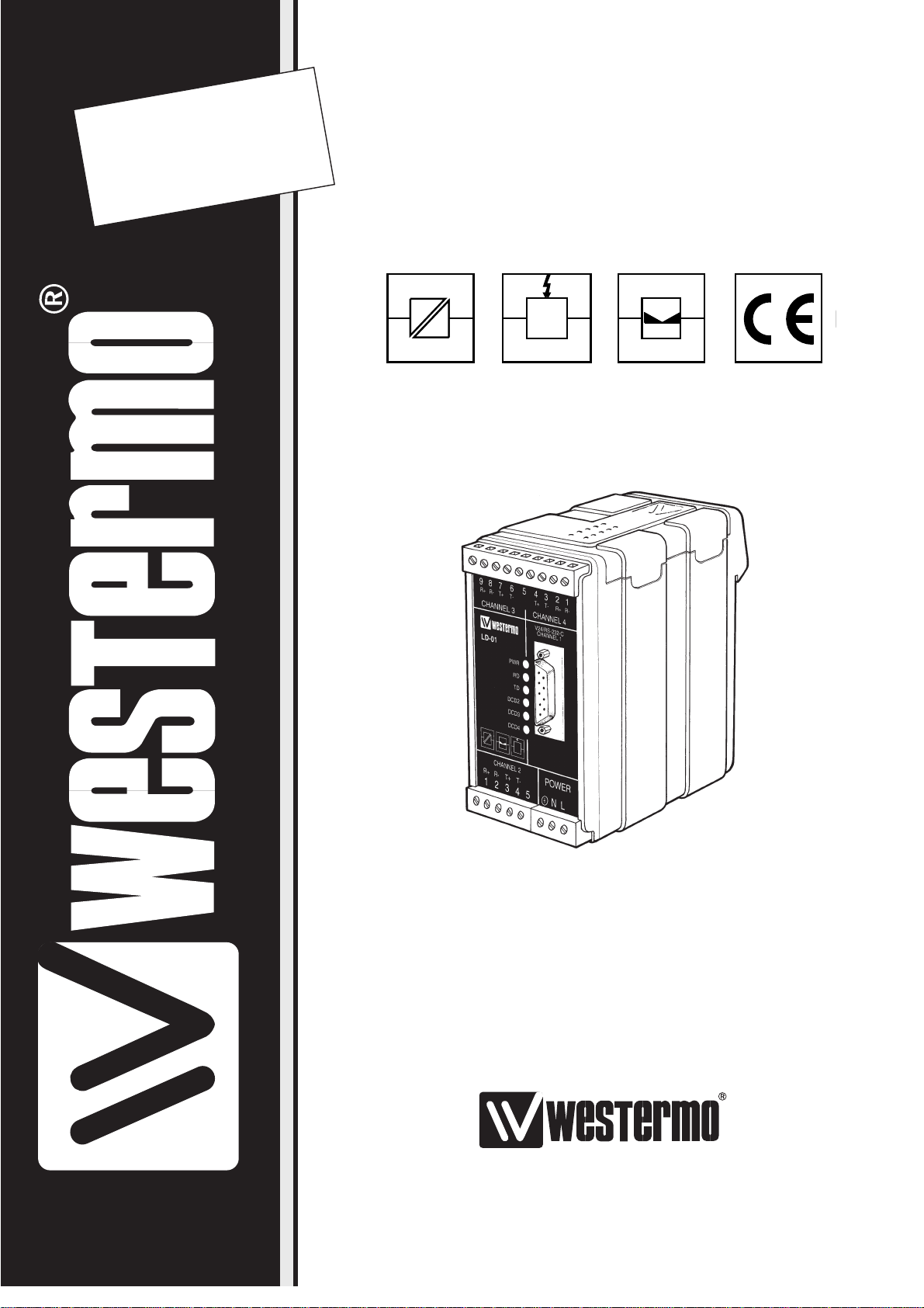
LD-01 AC
LD-01 DC
©
Westermo Teleindustri AB • 1999 • REV. A
Galvanic
Isolation
Transient
Protection
Balanced
TransmissionCEApproved
Page 2

8 6154-2001
Specifications LD-01
Transmission Asynchronous, full/half duplex or simplex
Interface 1 EIA RS-232-C/V.24 fixed on channel 1,
selectable on channel 2 and 3
Interface 2, (W1) 10 mA balanced current loop fixed on channel 4,
selectable on channel 2 and 3
Connection Channel 1: 9 pin D-sub female
Channel 2: 5 pos screw-terminal
Channel 3, 4: 9 pos screw-terminal
Transmission rate Data rates up to 38.4 Kbit/s
Indicators Power
Channel 1: RD, TD
Channel 2–4: DCD
Isolation Galvanic isolation with opto-coupler (Interface 2)
and transformer (supply)
Interface 1 only isolation against supply
Isolation voltage 1500V
Overvoltage protection Mains: Breakdown voltage 430V at 230V AC
and 230V at 115V AC*
Breakdown voltage transmitter 15V, receiver 5.8V
Surge capacity 0.6 kW during 1 ms
Power supply 115V*/230V AC 48–62Hz +15/–10%
Fuse 100 mA fast 5x20 mm
Power consumption Max 4VA at 115V*/230V AC
Temperature range 5–50°C, ambient temperature
Humidity 0-95% RH, non-condensing
Dimension 55x100x128 mm (WxHxD)
Weight, kg AC 0,5 / DC 0,3
Mounting On DIN-rail 35 mm
* LD-01 115V AC only
Page 3
96154-2001
WARNING!
DO NOT OPEN CONNECTED UNIT
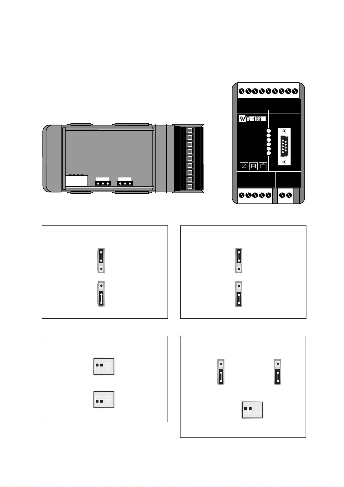
Switch settings
The LD-01 can through different switch settings be adapted to a variety of running
conditions. To set the switches, open the lid on the top of the plastic case.
V or Y function
Factory settings
Y
S1
ON
1234
V
S1
ON
1234
RS-232-C/V.24 or W1, Channel 2
RS-232-C/V.24
S1
ON
1234
J1
W1
J1
RS-232-C/V.24 or W1, Channel 3
S1:3 and 4 not used
See functional description
3
2
1
3
2
1
3
2
1
RS-232-C/V.24
J2
W1
J2
3
2
1
J1
3
2
1
J2
3
2
1
123456789
J1 J2
S1:1-4
1 2 3 1 2 3
987654321
R+ R- T+ T- T+ T- R+ R-
CHANNEL 3 CHANNEL 4
V24/RS-232-C
CONNECTION
LD-01 DC
DCD 2
DCD 3
DCD 4
CHANNEL 2
R+ R- T+ T-
12345
PWR
TD
RD
CHANNEL 1
POWER
12-36V
DC
+
-
Page 4

10 6154-2001
Direction RS-232-C/V.24 CCITT V.24 Description
DCE Channel 1 Channel 2 Channel 3 Circuit no.
O 1 109 DCD/Data Carier Detect
O 2 4 6 104 RD/Received Data
I 3 2 8 103 TD/Transmitted Data
I 4 108/2 DTR/Data Terminal Ready
– 5 5 5 102 SG/Signal Ground
O 6 107 DSR/Data Set Ready
I 7 105 RTS/Request To Send
O 8 106 CTS/Clear To Send
NC 9
Connections
Connection RS-232-C/V.24
Direction Pin configuration 10mA balanced current loop Signal name
Channel 2 Channel 3 Channel 4
Receiver 1 9 2 R+
Receiver 2 8 1 R-
Transmitter 3 7 4 T+
Transmitter 4 6 3 T-
5 5 5 1) Shield
Line connection
1) If shielded cable is used, connect the shield only at one end to avoid ground currents.
N 115V*/230V
L AC power
PE/Protective Earth
Power connection (AC)
(3-position screw-terminal)
* LD-01 115V only
Screw
no.
Power
Supply
I = Input O = Output, the LD-01 is a DCE (Data Communication Equipment) NC = Not connected
= the signals are only connected with each other.
Page 5

116154-2001
1 – Voltage
2 + Voltage
Transmission range (10mA balanced current loop W1)
Cable
42pF/m
0,3mm
2
Transmission data rate bit/s
1200
12000m
600
18000m
2400
8000m
4800
5000m
9600
2500m
19200
1000m
38400
500m
LD-01 DC
Specifications
Power supply 12–36V DC, 36–55V DC*
Power consumption Max 3W
Insulation 1000V
Fuse F1 1.6 A fast 5x20 mm
* LD-01 DC, 36–55V DC only
All other specifications according to LD-01 AC
Switch settings
According to LD-01 AC
Connections
According to LD-01 AC, except power supply
Connection
no
Power
Supply
Page 6

12 6154-2001
1
2
3
4
5
6
7
8
9
LD-01
1
2
3
4
5
6
7
8
9
9-pos. PC
1
2
3
4
5
6
7
8
9
10
11
12
13
14
15
16
17
18
19
20
21
22
23
24
25
1
2
3
4
5
6
7
8
9
DTE
LD-01
1
2
3
4
5
6
7
8
9
10
11
12
13
14
15
16
17
18
19
20
21
22
23
24
25
1
2
3
4
5
6
7
8
9
DCE
LD-01
Hints
LD-01 has four channels. Channel 1 has RS-232 interface and channel 2 and 3 can be
configured as RS-232 or W1 interface. Channel 4 has only W1 interface. The LD-01
splits the line and repeats the signal in a multidrop system. The maximum number of
units in serial connection is 14 units.
The drop channel (no 1) is configured as DCE (Data Communication Equipment). Most
printers, PC’s and terminals are set as DTE (Data Terminal Equipment). A recommendation of cable configurations is given below.
If any problems do occur on set up of the LD-01:s, the LED’s may be helpful.
• PWR: The unit has power.
• RD channel 1: Indicates transmitted data from channel 1
• TD channel 1: Indicates received data on channel 1
• DCD channel 2: Indicates that W1 is connected to channel 2
• DCD channel 3: Indicates that W1 is connected to channel 3
• DCD channel 4: Indicates that W1 is connected to channel 4
Page 7

136154-2001
OWN COMMENTS
.....................................................................................................................................................................................................................
.....................................................................................................................................................................................................................
.....................................................................................................................................................................................................................
.....................................................................................................................................................................................................................
.....................................................................................................................................................................................................................
.....................................................................................................................................................................................................................
.....................................................................................................................................................................................................................
.....................................................................................................................................................................................................................
.....................................................................................................................................................................................................................
.....................................................................................................................................................................................................................
.....................................................................................................................................................................................................................
.....................................................................................................................................................................................................................
.....................................................................................................................................................................................................................
.....................................................................................................................................................................................................................
.....................................................................................................................................................................................................................
Page 8

6154-2001 06.00 Mälartryck AB, Eskisltuna, Sweden
Westermo Teleindustri AB • S-640 40 Stora Sundby, Sweden
Phone +46 16 612 00 Fax +46 16 611 80
E-mail: info@westermo.se • Westermo Web site: www.westermo.se
Westermo Teleindustri AB have distributors in several countries,
contact us for further information.
Westermo Data Communications GmbH
Bruchsaler Straße 18, 68753 Waghäusel
Tel.: +49(0)7254-95400-0 • Fax.:+49(0)7254-95400-9
E-Mail: westermo.germany@t-online.de
Westermo Data Communications Ltd
Unit 14 Talisman Business Centre • Duncan Road
Park Gate, Southampton • SO31 7GA
Phone: +44(0)1489 580 585 • Fax.:+44(0)1489 580586
E-Mail: sales@westermo.co.uk • Web: www.westermo.co.uk
Subsidiaries
Functional Description
Communication between master and slaves.
Communication between all connected units.
V-function
OR
Channel 3Channel 2
Channel 1
Channel 4
Y-function
OR
OR
Channel 1
OR
Channel 4
Channel 3Channel 2
 Loading...