

Page 1
User Guide
6643-2220
REV. L
Lynx L108-F2G-S2 and
L208-F2G-S2
©Westermo Network Technologies AB
Industrial Ethernet 8-Port Device Server
Switch
www.westermo.com
Page 2

Table of Contents
1. General Information ........................................................................ 4
1.1. Legal Information ................................................................... 4
1.2. About This Guide ................................................................... 4
1.3. Software Tools ...................................................................... 4
1.4. License and Copyright for Included FLOSS ................................. 4
1.5. WeOS Management Guide ...................................................... 4
2. Safety and Regulations ................................................................... 5
2.1. Warning Levels ..................................................................... 5
2.2. Safety Information ................................................................. 6
2.3. Care Recommendations ......................................................... 7
2.4. Maintenance ......................................................................... 7
2.5. Product Disposal ................................................................... 7
2.6. Compliance Information .......................................................... 8
2.6.1. Agency Approvals and Standards Compliance .................... 8
2.6.2. FCC Part 15.105 Notice ................................................. 8
2.6.3. Corrosive Environment .................................................. 8
2.6.4. Simplified Declaration of Conformity .................................. 9
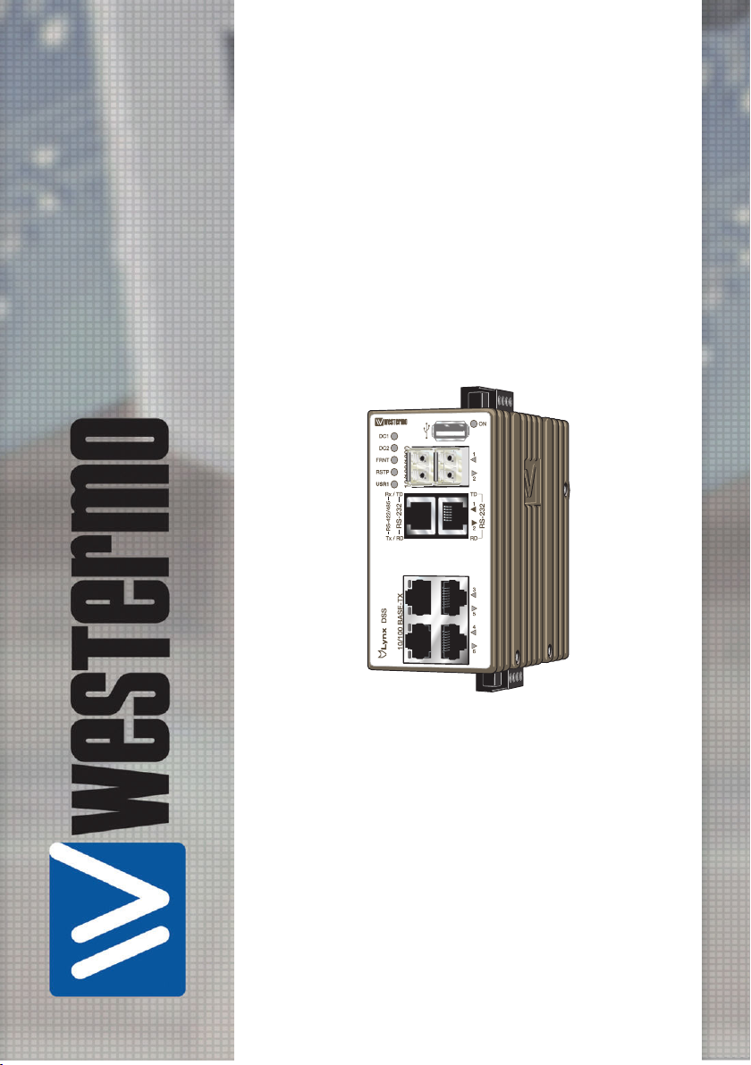
3. Product Description ...................................................................... 10
3.1. Product Description .............................................................. 10
3.2. Available Models ................................................................. 10
3.3. Hardware Overview ............................................................. 11
3.4. Connector Information .......................................................... 12
3.4.1. Ethernet Connection TX ............................................... 12
3.4.2. Power Input ............................................................... 12
3.4.3. I/O Connection ........................................................... 12
3.4.4. RS-232 Connection (DCE) ............................................ 13
3.4.5. RS-422/485 Connection ............................................... 14
3.4.6. USB Connection ......................................................... 15
3.5. LED Indicators .................................................................... 16
3.6. SFP Transceivers ................................................................ 17
3.6.1. Supported Transceivers ................................................ 17
3.6.2. Deviations ................................................................. 17
3.7. Dimensions ........................................................................ 17
4. Installation .................................................................................. 18
4.1. Mounting ........................................................................... 18
4.2. Removal of Product ............................................................. 18
4.3. Cooling .............................................................................. 19
4.4. Getting Started .................................................................... 19
4.5. Configuration Via a Web Browser ............................................ 20
4.6. Factory Default ................................................................... 20
5. Specifications .............................................................................. 22
5.1. Interface Specifications ......................................................... 22
Lynx L108-F2G-S2 and L208-
2
F2G-S2
Page 3

5.2. Type Tests and Environmental Conditions ................................. 25
6. Revision Notes ............................................................................ 28
Lynx L108-F2G-S2 and L208-
F2G-S2 3
Page 4

1. General Information
1.1. Legal Information
The contents of this document are provided “as is”. Except as required by applicable law,
no warranties of any kind are made in relation to the accuracy and reliability or contents of
this document, either expressed or implied, including but not limited to the implied
warranties of merchantability and fitness for a particular purpose. Westermo reserves the
right to revise this document or withdraw it at any time without prior notice.
Under no circumstances shall Westermo be responsible for any loss of data or income or
any special, incidental, and consequential or indirect damages howsoever caused.
More information about Westermo can be found at www.westermo.com.
1.2. About This Guide
This guide is intended for installation engineers and users of the Westermo products.
It includes information on safety and regulations, a product description, installation
instructions and technical specifications.
1.3. Software Tools
Related software tools are available at www.westermo.com/support/software-tools.
1.4. License and Copyright for Included FLOSS
This product includes software developed by third parties, including Free/Libre Open
Source Software (FLOSS). The specific license terms and copyright associated with the
software are included in each software package respectively. Please visit the product web
page for more information.
Upon request, the applicable source code will be provided. A nominal fee may be charged
to cover shipping and media. Please direct any source code request to your normal sales or
support channel.
1.5. WeOS Management Guide
This product runs WeOS (Westermo Operating System). Instructions for quick start,
configuration, factory reset and use of USB port are found in the WeOS Management
Guide at www.westermo.com.
Lynx L108-F2G-S2 and L208-
4
F2G-S2
Page 5
2. Safety and Regulations
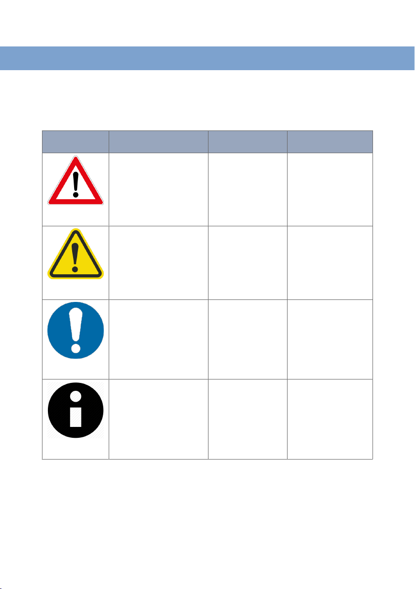
2.1. Warning Levels
Warning signs are provided to prevent personal injuries and/or damages to the product.
The following levels are used:
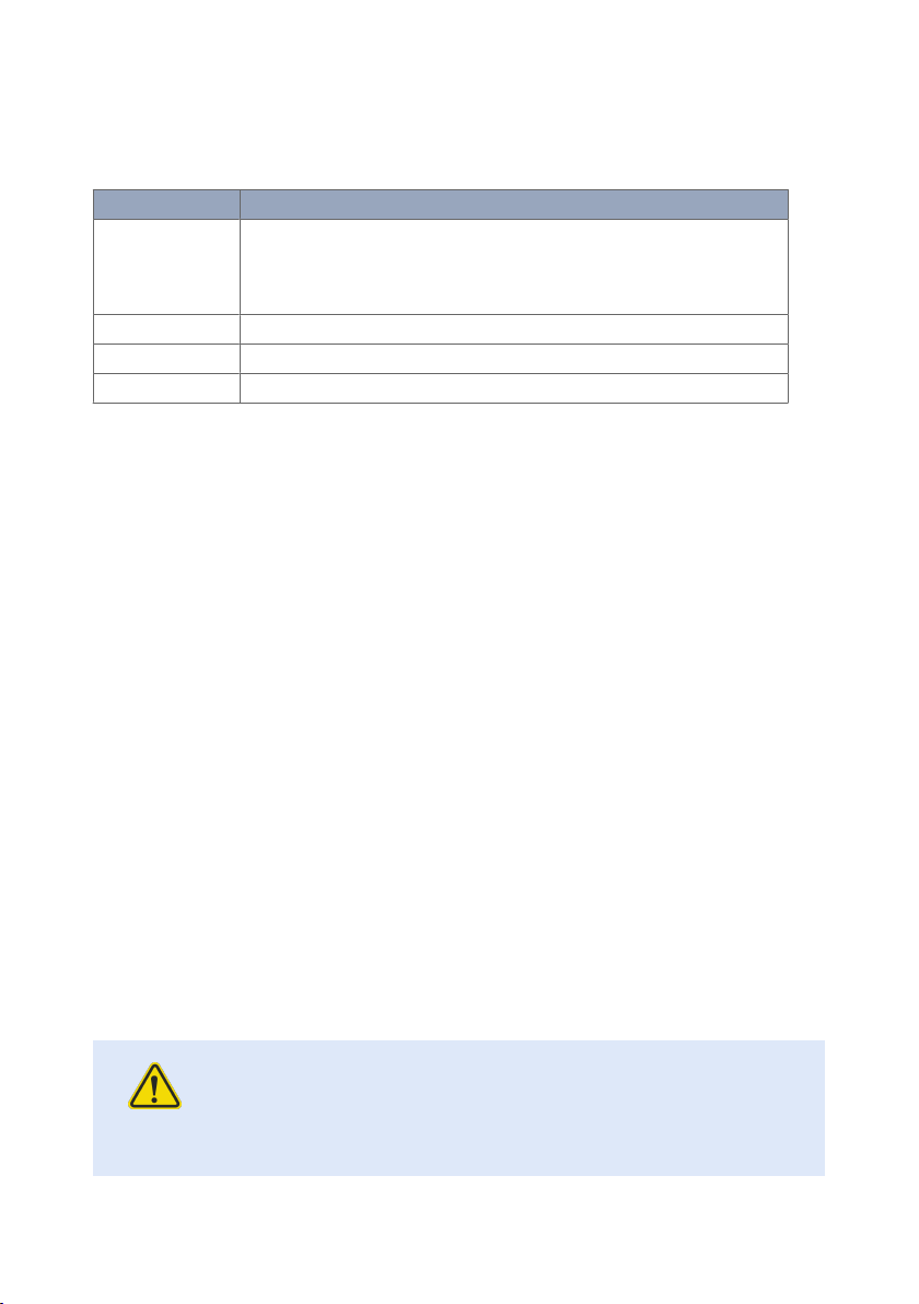
Level of warning
WARNING
CAUTION
NOTICE
Description Consequence
Indicates a potentially
hazardous situation
Indicates a potentially
hazardous situation
Provides information in order
to avoid misuse of the
product, confusion or
misunderstanding
Used for highlighting general,
but important information
personal injury
Possible death or major
injury
Minor or moderate
injury
No personal injury Minor damage to the
No personal injury Minor damage to the
Consequence
material damage
Major damage to the
product
Moderate damage to the
product
product
product
NOTE
Table 1. Warning levels
Lynx L108-F2G-S2 and L208-
F2G-S2 5
Page 6
2.2. Safety Information
Before installation:
Read this manual completely and gather all information available on the product. Make sure
it is fully understood. Check that your application does not exceed the safe operating
specifications for the product.
This product should only be installed by qualified personnel.
This product should be built-in to an apparatus cabinet or similar, where access is
restricted to service personnel only.
The power supply wiring must be sufficiently fused, and if necessary, it must be possible to
disconnect it manually from all power supply. Ensure compliance to national installation
regulations.
WARNING - PREVENT ACCESS TO HAZARDOUS VOLTAGE
Before mounting, using or removing this product: Prevent access to
hazardous voltage by disconnecting the product from all power supply.
WARNING - HAZARDOUS VOLTAGE
Do not open the connected product. Hazardous voltage may occur within
this product when connected to power supply.
WARNING - PROTECTIVE EARTHING
Before powering up, a protective earthing conductor must be connected
to the protective earthing terminal and have a cross-sectional area of at
least 4 mm2.
CAUTION - HOT SURFACE
Be aware of that the surface of this product may become hot. When this
product is operated at high temperatures, the external surface of the
product may exceed Touch Temperature Limit according to EN/IEC/UL
60950-1.
NOTICE - REDUCE RISK OF FIRE
To reduce the risk of fire, use only No. 26 (e.g. 24 AWG) UL listed or
CSA certified Telecommunication Line Cord.
Lynx L108-F2G-S2 and L208-
6
F2G-S2
Page 7
2.3. Care Recommendations
Follow the care recommendations below to maintain full operation of the product and to
fulfill the warranty obligations:
• Do not drop, knock or shake the product. Rough handling above the specification may
cause damage to internal circuit boards.
• Do not use harsh chemicals, cleaning solvents or strong detergents to clean the product.
• Do not paint the product. Paint can clog the product and prevent proper operation.
If the product is not working properly, contact the place of purchase, nearest Westermo
distributor office or Westermo Tech support.
2.4. Maintenance
No maintenance is required, as long as the product is used as intended within the specified
conditions.
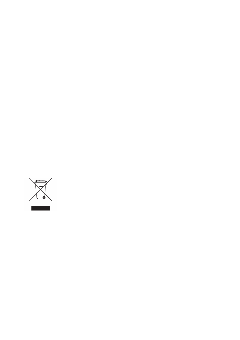
2.5. Product Disposal
This symbol means that the product shall not be treated as unsorted municipal waste when
disposing of it. It needs to be handed over to an applicable collection point for recycling
electrical and electronic equipment.
By ensuring the product is disposed of correctly, you will help to reduce hazardous
substances and prevent potential negative consequences to both environment and human
health, which could be caused by inappropriate disposal.
Figure 1. WEEE symbol for treatment of product disposal
Lynx L108-F2G-S2 and L208-
F2G-S2 7
Page 8
2.6. Compliance Information
2.6.1. Agency Approvals and Standards Compliance
Type
EMC • EN 61000-6-1, Immunity residential environments
Safety • EN/IEC/UL 60950-1, IT equipment
a
Marine
Environmental
a
Only valid for L108-F2G-S2
b
Only valid for L108-F2G-S2-12VDC
Approval/Compliance
• EN 61000-6-2, Immunity industrial environments
• EN 61000-6-4, Emission industrial environments
• EN 50121-3-2/IEC 62236-3-2 Railway applications – Rolling stock – apparatus
• DNV GL rules for classification - Ships and offshore units
b
• NEMA TS 2, Traffic Controller Assemblies with NTCIP Requirements
Table 2. Agency approvals and standards compliance
2.6.2. FCC Part 15.105 Notice
This product has been tested and found to comply with the limits for a Class B digital
device, pursuant to Part 15 of the FCC Rules. These limits are designed to provide
reasonable protection against harmful interference in a residential installation. This product
generates, uses and can radiate radio frequency energy and, if not installed and used in
accordance with the instructions, may cause harmful interference to radio communications.
However, there is no guarantee that interference will not occur in a particular installation.
If this product does cause harmful interference to radio or television reception, which can
be determined by turning the product off and on, the user is encouraged to try to correct
the interference by one or more of the following measures:
• Reorient or relocate the receiving antenna
• Increase the separation between the unit and receiver
• Connect the product into an outlet on a circuit different from that to which the receiver
is connected
• Consult the dealer or an experienced radio/TV technician for help
2.6.3. Corrosive Environment
This product has been successfully tested in a corrosion test according to IEC 60068- 2-60,
method 3. This means that the product meets the requirements to be placed in an
environment classified as ISA-S71.04 class G3.
CAUTION - CORROSIVE GASES
If the product is placed in a corrosive environment, it is important that all
unused connector sockets are protected with a suitable plug, in order to
avoid corrosion attacks on the gold plated connector pins.
Lynx L108-F2G-S2 and L208-
8
F2G-S2
Page 9

2.6.4. Simplified Declaration of Conformity
Hereby, Westermo declares that this product is in compliance with applicable EU
directives. The full EU declaration of conformity and other detailed information is available
at www.westermo.com/support/product-support.
Figure 2. The European conformity marking
Lynx L108-F2G-S2 and L208-
F2G-S2 9
Page 10

3. Product Description
3.1. Product Description
Lynx DSS is a device server with a managed layer 2 and 3 industrial Ethernet switch,
powered by the Westermo WeOS network operating system. It is the most compact and
has the lowest power requirements in this class of device servers.
Lynx DSS is the most compact, and has the lowest power requirements, in this class of
device servers. It has four pieces of 10/100 Mbit/s ports in addition to two ports which can
be fitted with Gbit or 100 Mbit SFP transceivers and two serial ports. One serial port is
configured for RS-232, the other one can be configured for either RS-232 or RS-422/485.
Lynx DSS is designed for simple use in industrial applications, from the robust DIN rail clip
solution to the configurable fault contact and the industrial level of dual power inputs.
Only industrial grade components are used which gives Lynx DSS an MTBF of 517,000
hours and ensures a long service life. A wide operating temperature range of -40 to +70°C
(-40 to +158°F) can be achieved with no moving parts or cooling holes in the case. Lynx
DSS has been tested both by Westermo and external test institutes to meet many EMC,
isolation, vibration and shock standards, all to the highest levels suitable for heavy industrial
environments and rail trackside applications.
WeOS has been developed by Westermo to offer cross platform and future proof
solutions. For more WeOS functionality, please see the WeOS datasheet.
3.2. Available Models
Art. no.
3643-0200 L108-F2G-S2 4 2 2 L2 24-48 VDC
3643-0240 L108-F2G-
3643-0205 L208-F2G-S2 4 2 2 L3 24-48 VDC
Model 100 Mbit
TX ports
S2-12VDC
Gbit SFP
ports
4 2 2 L2 12-48 VDC
Serial
ports
Software
Rated
voltage
Lynx L108-F2G-S2 and L208-
10
F2G-S2
Page 11

3.3. Hardware Overview
421
6 5
3
8
7
3
2
1
No. Description No. Description
1 LED indicators 2 SFP transceivers
3 USB connection 4 Power connection
5 I/O connection 6 Ethernet connection
7 RS-232 connection 8 RS-232 and RS-422/485 connection
Figure 3. Location of interface ports and LED indicators
No.
Figure 4. Location of interface ports, bottom view
Description No. Description
1 I/O connection 2 Console port
3 Accessorie cable, art. no. 1211-2027
Lynx L108-F2G-S2 and L208-
F2G-S2 11
Page 12

3.4. Connector Information
1
2
3
4
1
2
3
4
3.4.1. Ethernet Connection TX
Illustration
Pin no. Signal Direction Description
1 TD+ In/Out Transmitted/Received data
2 TD- In/Out Transmitted/Received data
3 RD+ In/Out Transmitted/Received data
4 - - Not connected
5 - - Not connected
6 RD- In/Out Transmitted/Received data
7 - - Not connected
8 - - Not connected
Shield Connected to PE
Table 3. Ethernet connection TX
3.4.2. Power Input
Illustration
Position Product
marking
1 +DC1 Input Supply
2 +DC2 Input Supply
3 -COM Input Common
4 -COM Input Common
Table 4. Power input
Direction
Description
voltage
voltage
Lynx supports redundant power connection. The positive inputs are +DC1 and +DC2, the
negative input for both supplies are -COM. Connect the primary voltage (e.g. +24 VDC) to
the +DC1 pin and return to one of the -COM pins on the power input.
3.4.3. I/O Connection
Illustration
Pin no. Product marking Direction Description
1 Status + Output Alarm relay (status) contact
2 Status - Output Alarm relay (status) contact
3 Digital in + Input Digital in +
4 Digital in - Input Digital in -
Table 5. I/O connection
12
Lynx L108-F2G-S2 and L208-
F2G-S2
Page 13

The Status output is a potential free, opto-isolated, normally closed, solit-state relay. This
External load
Status
V
V
Digital in
Lynx
+
-
+
-
3
4
1
2
Pin 8 Pin 1
can be configured to monitor various alarm events within the unit, see WeOS Management
Guide. An external load in series with an external voltage source is required for proper
functionality. For voltage/current, see Interface Specification section.
The Digital in is an opto-isolated digital input, which can be used to monitor external
events. For voltage/current, see Interface Specification section.
Figure 5. Digital in
3.4.4. RS-232 Connection (DCE)
Illustration
Table 6. RS-232 connection
Pin no. Signal Direction Description
1 DSR Out Data Set Ready
2 DCD Out Data Carrier Detect
3 DTR In Data Terminal Ready
4 SG - Signal Ground, not chassis ground
5 RD Out Receive Data
6 TD In Transmit Data
7 CTS Out Clear To Send
8 RTS In Request To Send
Lynx L108-F2G-S2 and L208-
F2G-S2 13
Page 14

3.4.5. RS-422/485 Connection
Pin 8 Pin 1
No termination
Rx
Terminate RxTerminate Tx
Tx
Rx
Tx
Rx
Tx
Rx
Tx
Terminate Tx and Rx
No termination
Termination
Illustration Pin no. Signal Direction Description
RS-422 (4wire)
RS-485 (2wire)
1 T+ T+/R+ Out/In RS-422: Transmit
RS-485: Transmit/
Receive
2 T- T-/R- Out/In RS-422: Transmit
RS-485: Transmit/
Receive
3 R- - In RS-422: Receive
4 - - - Not used
5 - - - Not used
6 R+ - In RS-422: Receive
7 - - - Not used
8 - - - Not used
Table 7. RS-422/485 connection
Lynx is equipped with with an internal termination that is configurable through software in
RS-422/485 mode. The following termination schemes are supported:
Figure 6. RS-422 termination scheme
Figure 7. RS-485 termination scheme
14
Lynx L108-F2G-S2 and L208-
F2G-S2
Page 15

When the unit is powered off or during reboot, any internal termination will be
disconnected from the signal lines.
NOTE
NOTE - The port is configurable for both RS-232 and RS-422/485, hence
no fail-safe biasing is available for RS-422/485 signals.
3.4.6. USB Connection
Illustration
Pin
no.
1 Out VBUS
2 In/Out D-
3 In/Out D+
4 Out GND
5 In/Out Connected to
Table 8. USB connection
Direction
Description
protective earth
Lynx L108-F2G-S2 and L208-
F2G-S2 15
Page 16

3.5. LED Indicators
LED Status Description
ON OFF Product has no power
GREEN All OK, no alarm condition
RED Alarm condition, or until product has started
BLINK Location indicator ("Here I am!"). Activated
DC1 OFF Product has no power
GREEN Power OK on DC1
RED Power failure on +DC1
DC2 OFF Product has no power
GREEN Power OK on DC2
RED Power failure on +DC2
FRNT OFF FRNT disabled
GREEN FRNT OK
RED FRNT error
BLINK Product configured as FRNT focal point
RSTP OFF RSTP disabled
GREEN RSTP enabled
BLINK Product selected as RSTP/STP root switch
USR1 Configurable, see WeOS Management Guide
Rx/TD,
TD
Tx/RD,
RD
1 to 6 OFF No link
OFF No serial data received
GREEN
FLASH
OFF No serial data transmitted
GREEN
FLASH
GREEN Link established
GREEN
FLASH
YELLOW Por t alarm and no link. Or if FRNT or RSTP
up. (Alarm conditions are configurable, see
WeOS Management Guide)
when connected to WeConfig tool, or upon
request from web or/and CLI. RED BLINK
during boot indicates pending cable factory
reset.
Serial data received
Serial data transmitted
Data traffic indication
mode, port is blocked.
Table 9. LED indicators
16
Lynx L108-F2G-S2 and L208-
F2G-S2
Page 17

3.6. SFP Transceivers
92
±1
Min 4mm
Max 7,5mm
34
±1
96
±1
52
±1
100
±1
3.6.1. Supported Transceivers
Firmware prior to 4.4.0 accepts Westermo branded transceivers only. From 4.5.0 other
transceivers are accepted with a notice and the product will no longer be UL approved.
Temperature specifications are also depending on the used transceivers.
NOTICE - SUPPORTED TRANSCEIVERS
To comply with UL60950-1, only UL recognised SFP transceivers should
be used.
3.6.2. Deviations
With copper transceiver 1100-0148, the specified operating temperature of the product is
0 to 50ºC. FRNT reconfiguration times can not be guaranteed with copper transceivers.
3.7. Dimensions
Dimensions are stated in mm and are regardless of Lynx model.
Figure 8. Dimensional drawing
Lynx L108-F2G-S2 and L208-
F2G-S2 17
Page 18

4. Installation
4.1. Mounting
This product should be mounted on a 35 mm DIN-rail, which is horizontally mounted
inside an apparatus cabinet or similar. It is recommended that the DIN-rail is connected to
ground. Snap on the product to the DIN-rail according to the figure.
Figure 9. Mounting of product
4.2. Removal of Product
To remove the product that has an integrated DIN-clip, press down the support at the
back with a screwdriver.
Figure 10. Removal of product
18
Lynx L108-F2G-S2 and L208-
F2G-S2
Page 19

4.3. Cooling
10mm10mm
This product uses convection cooling. Spacing is recommended for the use of the product
in full operating temperature range and service life. To avoid obstructing the airflow around
the product, use the following spacing rules.
Minimum spacing of 25 mm (1 inch) above/below and 10 mm (0.4 inches) left/right of the
productis recommended.
Figure 11. Miminum spacing of product
4.4. Getting Started
This product runs the Westermo Operating System (WeOS) which provides several
management tools that can be used for configuration of the unit.
•
WeConfig tool
This is a custom Westermo tool used for discovery of attached Westermo product.
•
Web
Configuration of the product using the web browser.
•
CLI
Configuration of the product via the Command Line Interface.
Username: admin
Password: westermo
If the computer is located in the same subnet as the switch you can easily use a web
browser to configure the product. Within the web you can configure most of the available
functions. If you are not sure about the subnet – consult your network administrator.
For advanced network settings and more diagnostic information, please use the CLI.
Detailed documentation is available in the chapter ”The Command Line Management Tool” in
the WeOS Management Guide.
Factory default:
Lynx L108-F2G-S2 and L208-
F2G-S2 19
Page 20

IP address: 192.168.2.200
Netmask: 255.255.255.0
Gateway: disabled
4.5. Configuration Via a Web Browser
The product can easily be configured via a web browser. Open the link http://192.168.2.200
in your web browser, and you will be prompted with a login screen, where the default
settings are:
Username: admin
Password: westermo
Once logged in, use the extensive integrated help function describing all configuration
options.
Two common task when configuring a new switch is to assign appropriate IP settings, and
to change the password of the admin account. The password can be up to 64 characters
long, and should consist of printable ASCII characters (ASCII 33-126); 'Space' is not a valid
password character.
NOTE
Note! Version of WeConfig tool must be 10.3.0 or higher.
4.6. Factory Default
It is possible to set the product to factory default settings by using two straight standard
Ethernet RJ-45 cables.
1. Power off the product and disconnect all Ethernet cables (copper and fibre).
2. Connect one Ethernet cable between Ethernet ports 3 and 6, and the other between
Ethernet ports 4 and5. The ports need to be connected directly by an Ethernet cable,
i.e., not via a hub or switch. Use a straight cable – not a cross-over cable – when
connecting the ports.
3. Power on the product.
4. Wait for the product to start up. Control that the ON LED is flashing red. The
product is now ready to be either reset to factory default or to boot as normal.
To go ahead with factory reset:
NOTE
Do not power off the product while the factory reset process is in
progress.
Lynx L108-F2G-S2 and L208-
20
F2G-S2
Page 21

• Acknowledge that you wish to conduct the factory reset by unplugging the Ethernet
cables. The ON LED will stop flashing. This initiates the factory reset process, and after
approximately 1 minute the product will restart with factory default settings. When the
product has booted up, the ON LED will show a green light, and is now ready to use.
To boot as normal:
• To skip the factory reset process, just wait for approximately 30 seconds (after the ON
LED starts flashing RED) without unplugging the Ethernet cables. The product will
conduct a normal boot with the existing settings.
Lynx L108-F2G-S2 and L208-
F2G-S2 21
Page 22

5. Specifications
5.1. Interface Specifications
DC, Power port
L108-F2G-S2-12VDC: Lx08-F2G-S2:
Rated voltage 12 - 24 VDC 24 - 48 VDC
Operating voltage 9.8 - 36 VDC 19 - 60 VDC
Rated current 470 mA (820 mA) at 12 VDC (with
Rated frequency DC
Inrush current, I²t 102 mA2s at 12 VDC
Startup current
Polarity Reverse polarity protected
Redundant power input Yes
Isolation All other ports
Connector Detachable screw terminal
Connector size 0.2-2.5 mm² (AWG 24-12)
Shielded cable Not required
a
External supply current capability for proper startup
a
500 mA USB load)
230 mA (390 mA) at 24 VDC (with
500 mA USB load)
71,2 mA2s at 24 VDC
2 x rated current
250 mA (380 mA) at 24 VDC
(with 500 mA USB load)
120 mA (188 mA) at 48 VDC
(with 500 mA USB load)
22.7 mA2s at 48 VDC
Ethernet TX
Electrical specification IEEE std 802.3
Data rate 10 Mbit/s, 100 Mbit/s, manual or auto
Duplex Full or half, manual or auto
Circuit type TNV-1
Transmission range Up to 150 m with CAT5e cable or better
Isolation All other ports
Connection RJ-45, auto MDI/MDI-X
Cabling Shielded CAT5e or better is recommended
Conductive chassis Yes
Number of ports 4
Lynx L108-F2G-S2 and L208-
22
F2G-S2
Page 23

Ethernet SFP pluggable connections (FX or TX)
Electrical specification IEEE std 802.3
Data rate 100 Mbit/s, 1000 Mbit/s, transceivers suppor ted
Duplex Full or Auto, depending on transceiver
Transmission range Depending on transceiver, see datasheet for SFP transceivers
Connection SFP slot holding fibre transceiver or copper transceiver
Number of ports 1 or 2
RS-232
Electrical specification EIA RS-232
Data rate 300 bit/s - 115.2 kbit/s
Data format 7 or 8 data bits, odd, even or none parity, 1 or 2 stop bits
Protocol Transparent, optimised by packing algorithm
Circuit type SELV
Transmission range 15 m/49 ft
Isolation To all other por ts
Connection RJ-45 according to EIA-561
Shielded cable Recommended
Conductive chassis Yes
Number of ports 1
RS-422/485
Electrical specification Configurable for EIA RS-232 or EIA RS-422/485
Data rate 50 bit/s - 2 Mbit/s
Data format 7 or 8 data bits, odd, even or none parity, 1 or 2 stop bits (2 stop bits only
when no parity is set)V
Circuit type TNV-1
Transmission range Up to 1200 m/0.74 mi, depending on data rate and cable type
Isolation To all other por ts
Connection RJ-45 according to EIA-561
Shielded cable Shielded cable not required, except when installed in Railway application
as signalling and telecommunications apparatus and located close to rails
Conductive chassis Yes
Number of ports 1
a
To minimise the risk of interference, a shielded cable is recommended when the cable is located inside 3 m
boundary or the cable is longer than 30 m and inside 10 m boundary to the rails and connected to this port.
a
Lynx L108-F2G-S2 and L208-
F2G-S2 23
Page 24

I/O connection, Relay output
Maximum voltage/current 60 VDC/80 mA
Connect resistance Maximum 30 Ω
Isolation To all other por ts
Connector Detachable screw terminal
Connector size 0.2 - 2.5 mm² (AWG 24-12)
I/O connection, Digital input
Maximum voltage/current 60 VDC/2mA
Voltage levels Logic one: >12 V
Isolation To all other por ts
Connector Detachable screw terminal
Connector size 0.2 - 2.5 mm² (AWG 24-12)
USB
Electrical specification USB 2.0 hose interface
Data rate Up to 12 Mbit/s (full speed mode)
Circuit type SELV
Maximum supply current 500 mA
Connection USB receptable connector type A
Logic zero: <1 V
Console port
Electrical specification LVTTL-level (ser vice port, shall not be connected during normal
Data rate 115.2 kbit/s
Circuit type SELV
Data format 8 data bits, no parity, 1 stop bit, no flow control
Connection 2.5 mm jack, use only Westermo cable 1211-2027
operation. Only to be used during maintenance.)
Lynx L108-F2G-S2 and L208-
24
F2G-S2
Page 25

5.2. Type Tests and Environmental Conditions
Environmental
phenomena
ESD EN 61000-4-2 Enclosure Contact: ±6 kV
Fast transients EN 61000-4-4 Power port ± 2 kV
Surge EN 61000-4-5 Power port L-L: ± 0.5 kV, 2 Ω, 18 µF
Power frequency
magnetic field
Pulsed magnetic field EN 61000-4-9 Enclosure 300 A/m
Radiated RF immunity EN 61000-4-3 Enclosure 10 V/m at (80 - 800) MHz)
Conducted RF
immunity
Radiated RF emission CISPR 16-2-3
Conducted RF emission CISPR 16-2-3
Basic standard
EN 61000-4-8 Enclosure 300 A/m; 0, 16.7, 60 Hz
EN 61000-4-6 Power port 10 V, 80% AM, 1 kHz; (0.15-80)
ANSI C63,4
(FCC Part 15)
ANSI C63,4
(FCC Part 15b)
Description Test levels
Air: ±8 kV
Ethernet
Status out/Digital in
Serial ports
Enclosure
L-E: ± 2 kV, 42 Ω, 0.5 µF
L-L: ± 1 kV, 42 Ω, 0,5 µF
L-E: ± 2 kV, 12 Ω, 9 µF
L-L: ± 1 kV, 12 Ω, 9 µF
Ethernet L-E: ± 2 kV, 2 Ω, 0.5 µF
Status out/Digital in L-E: ± 2 kV, 42 Ω, 0.5 µF
RS-232 L-E: ± 2 kV, 2 Ω, 0,5 µF
RS-422/485 L-E: ± 2 kV, 42 Ω, 0,5 µF
Ethernet
Status out/Digital in
Serial ports
Earth por t
Enclosure Class B/DNV bridge
Power port Class B/DNV bridge
Ethernet Class B
L-L: ± 1 kV, 42 Ω, 0,5 µF
1000 A/m; 50 Hz
20 V/m at (800 - 1000) MHz
10 V/m at (1.4 - 2.1) GHz
5 V/m at (2.1 - 2.5) GHz
1 V/m at (2.5 - 2.7) GHz
1 kHz sine, 80% AM
MHz
Lynx L108-F2G-S2 and L208-
F2G-S2 25
Page 26

Environmental
phenomena
Compass safe distance DNV Enclosure Standard compass (5.4°/H
Dielectric strength EN 60950-1 Power port to all
Basic standard
Description Test levels
deviation) = 15 cm
Steering/standby steering /
emergency compass (18°/H
deviation) = 10 cm
1.5 kVrms, 50 Hz, 1 min
other ports
Ethernet ports to all
other ports
RS-322 port to all
other ports
RS-422/485 port to
all other ports
Table 10. EMC and electrical conditions
26
Lynx L108-F2G-S2 and L208-
F2G-S2
Page 27

Environmental
phenomena
Basic
standard
Temperatures EN 60068-2-1
EN 60068-2-2
Description
Operating L108-F2G-S2-12VDC: -40 to +74°C (-40
Test levels
to +165°F)
a
Lx08-F2G-S2: -40 to +70°C (-40 to
+158°F)
Storage and
-50 to +85°C (-58 to +185°F)
transport
Humidity EN 60068-2-30 Operating 5-95% relative humidity
Storage and
transport
Altitude Operating 2000 m/70 kPa
Service life Operating 10 years
MTBF MIL-C217F2,
517,000 hours
Parts count
Vibration IEC 60068-2-6
(sine)
Operating 3 - 13.2 Hz: 1 mm
13.2 - 100 Hz 0.7 g
5.5 - 30 Hz: 1.5 g
IEC
60068-2-64
30 - 50 Hz: 0.42 mm
50 - 500 Hz: 4.2 g
Operating 5 - 20 Hz: 2 m2/s
20 - 2000 Hz - 3 dB/oct
b
2
(random)
Shock IEC
60068-2-27
Bump IEC
Operating 30 g, 11 ms
100 g, 6 ms
Operating 10 g, 11 ms
b
60068-2-27
Enclosure EN 60950-1 Zinc Fire enclosure
Weight 0.7 kg
Degree of protection EN 60529 Enclosure IP40
Cooling Convection
a
Refer to "Safety and Regulations" chapter regarding touch temperature
b
Might require Ethernet cables to be fastened close to the unit.
Table 11. Environmental and mechanical conditions
Lynx L108-F2G-S2 and L208-
F2G-S2 27
Page 28

6. Revision Notes
Revision
Rev. L 2019-04 Added product L108-F2G-S2-12VDC and references to it - frontpage,
Date Change description
2.6.1 Agency approvals and Standards Compliance, 3.1 Product
Description, 5.1 Interface Specifications, 5.2 Type Tests and Environmental
Conditions
28
Lynx L108-F2G-S2 and L208-
F2G-S2
Page 29

Lynx L108-F2G-S2 and L208-
F2G-S2
Page 30

Lynx L108-F2G-S2 and L208-
F2G-S2
Page 31

Lynx L108-F2G-S2 and L208-
F2G-S2
Page 32

Westermo • SE-635 35 Stora Sundby, Sweden
Tel +46 16 42 80 00 Fax +46 16 42 80 01
E-mail: info@westermo.com
www.westermo.com
6643-2220 REV. L 2019 04 Westermo Network Technologies AB, Sweden
 Loading...