

Page 1
User Guide
6620-2200
IDW-90
Westermo Teleindustri AB
©
ISDN
Terminaladapter
www.westermo.com
Page 2

2
6620-2200
Legal information
The contents of this document are provided “as is”. Except as required by applicable
law, no warranties of any kind, either express or implied, including, but not limited to,
the implied warranties of merchantability and fitness for a particular purpose, are made
in relation to the accuracy and reliability or contents of this document. Westermo
reserves the right to revise this document or withdraw it at any time without prior
notice.
Under no circumstances shall Westermo be responsible for any loss of data or income
or any special, incidental, and consequential or indirect damages howsoever caused.
More information about Westermo can be found at the following Internet address:
http://www.westermo.com
Page 3

3
6620-2200
Safety
!
!
Before installation:
Read this manual completely and gather all information on the unit. Make sure that
you understand it fully. Check that your application does not exceed the safe operating specifications for this unit.
This unit should only be installed by qualified personnel.
This unit should be built-in to an apparatus cabinet, or similar, where access is
restricted to service personnel only.
The power supply wiring must be sufficiently fused, and if necessary it must be
possible to disconnect manually from the power supply. Ensure compliance to
national installation regulations.
This unit uses convection cooling. To avoid obstructing the airflow around the unit,
follow the spacing recommendations (see Cooling section).
Before mounting, using or removing this unit:
Prevent access to hazardous voltage by disconnecting the unit from power supply.
Warning! Do not open connected unit. Hazardous voltage may occur within this
unit when connected to power supply.
Care recommendations
Follow the care recommendations below to maintain full operation of unit and to fulfil
the warranty obligations.
This unit must not be operating with removed covers or lids.
Do not attempt to disassemble the unit. There are no user serviceable parts inside.
Do not drop, knock or shake the unit, rough handling above the specification may cause
damage to internal circuit boards.
Do not use harsh chemicals, cleaning solvents or strong detergents to clean the unit.
Do not paint the unit. Paint can clog the unit and prevent proper operation.
Do not expose the unit to any kind of liquids (rain, beverages, etc). The unit is not water-
proof. Keep the unit within the specified humidity levels.
Do not use or store the unit in dusty, dirty areas, connectors as well as other mechanical
part may be damaged.
If the unit is not working properly, contact the place of purchase, nearest Westermo dis-
tributor office or Westermo Tech support.
Fibre connectors are supplied with plugs to avoid contamination inside the optical port.
As long as no optical fibre is mounted on the connector, e.g. for storage, service or
transportation, should the plug be applied.
Maintenance
No maintenance is required, as long as the unit is used as intended within the specified
conditions.
Page 4

4
6620-2200
Agency approvals and standards compliance
Type Approval / Compliance
EMC EN 61000-6-2, Immunity industrial environments
EN 55024, Immunity IT equipment
EN 61000-6-3, Emission residential environments
FCC part 15 Class B
EN 50121-4, Railway signalling and telecommunications apparatus
IEC 62236-4, Railway signalling and telecommunications apparatus
Safety EN 60950-1, IT equipment
ISDN TBR-3
FCC Part 15.105 Notice:
This equipment has been tested and found to comply with the limits for a
Class B digital device, pursuant to Part 15 of the FCC Rules. These limits
are designed to provide reasonable protection against harmful interference
in a residential installation. This equipment generates, uses and can radiate
radio frequency energy and, if not installed and used in accordance with
the instructions, may cause harmful interference to radio communications.
However, there is no guarantee that interference will not occur in a particular installation. If this equipment does cause harmful interference to radio
or television reception, which can be determined by turning the equipment
off and on, the user is encouraged to try to correct the interference by
one or more of the following measures:
… Reorient or relocate the receiving antenna
… Increase the separation between the equipment and receiver
… Connect the equipment into an outlet on a circuit different from that to
which the receiver is connected
… Consult the dealer or an experienced radio/TV technician for help.
Page 5
5
6620-2200
Declaration of Conformity
Westermo T eleindustri AB
Declaration of conformity
Org.nr/
Postadress/Postal address
Tel.
Telefax
Postgiro
Bankgiro Corp. identity number Registered office
S-640 40 Stora Sundby 016-428000 016-428001 52 72 79-4 5671-5550 556361-2604 Eskilstuna
Sweden Int+46 16428000 I nt+46 16428001
The manufacturer
Westermo Teleindustri AB
SE-640 40 Stora Sundby, Sweden
Herewith declares that the product(s)
Type of product Model Art no
ISDN adapter with PSTN modem IDW-90 3620-0001
is in conformity with the following EC directive(s).
No Short name
2004/108/EC Electromagnetic Compatibility (EMC)
1999/5/EC Radio and Telecommunications Terminal Equipment (R&TTE)
2011/65/EU Restriction of the use of certain hazardous substances in electrical and electronic
equipment (RoHS)
References of standards applied for this EC declaration of conformity.
No Title Issue
EN 61000-6-1 Electromagnetic compatibility – Immunity for residential
environments
2007
EN 61000-6-2 Electromagnetic compatibility – Immunity for industrial
environments
2005
+ C1: 2005
EN 61000-6-3 Electromagnetic compatibility – Emission for residential
environments
2007
+ A1: 2011
EN 61000-6-4 Electromagnetic compatibility – Emission for industrial
environments
2007
+ A1:2011
EN 55022 Information technology equipment - Radio disturbance
characteristics - Limits and methods of measurement
2010
EN 55024 Information technology equipment - Immunity characteristics -
Limits and methods of measurement
2010
EN 50121-4 Railway applications - Electromagnetic compatibility
Emission and immunity of the signalling and telecommunications
apparatus
2006
+ C1: 2008
EN 60950-1
Safety of information technology equipment 2006
+ A1: 2010
+ A2: 2013
+ AC1: 2012
+ A11: 2009
+ A12: 2011
EN 50581 Technical documentation for the assessment of electrical and
electronic products with respect to the restriction of hazardous
substances
2012
The last two digits of the year in which the CE marking was affixed: 14
Pierre Öberg
Technical Manager
14
th
April 2014
Page 6

6
6620-2200
Type tests and environmental conditions
Electromagnetic Compatibility
Phenomena Test Description Test levels
ESD EN 61000-4-2 Enclosure contact ± 6 kV
RF field AM modulated
RF field 900 MHz ENV 50204 Enclosure 20 V/m pulse modulated 200 Hz, 900 ± 5 MHz
Fast transient EN 61000-4-4 Signal ports ± 2 kV
Surge EN 61000-4-5 Signal ports unbal-
RF conducted EN 61000-4-6 Signal ports 10 V 80% AM (1 kHz), 0.15 – 80 MHz
Power frequency
magnetic field
Pulse magnetic field EN 61000-4-9 Enclosure 300 A/m, 6.4 / 16 ms pulse
Mains freq. 50 Hz EN 61000-4-16 Signal ports 100 V 50 Hz line to earth
Mains freq. 50 Hz SS 436 15 03 Signal ports 250 V 50 Hz line to line
Voltage dips and
interruption
Radiated emission EN 55022 Enclosure Class B
Conducted emission EN 55022 DC power ports Class B
Dielectric strength EN 60950 Signal port to other
Environmental
Temperature Operating +5 to +55ºC /
Humidity Operating 5 to 95% relative humidity
Altitude Operating 2 000 m / 70 kPa
Reliability prediction
(MTBF)
Service life Operating 10 year
Vibration IEC 60068-2-6 Operating 7.5 mm, 5 – 8 Hz 2 g, 8 – 500 Hz
Shock IEC 60068-2-27 Operating 15 g, 11 ms
Packaging
Phenomena Test Description Level
Enclosure UL 94 PC / ABS Flammability class V-1
Dimension
W x H x D
Weight 0.25 kg
Degree
of protection
Cooling Convection
Mounting Horizontal on 35 mm DIN-rail
IEC 61000-4-3 Enclosure 10 V/m 80% AM (1 kHz), 80 – 1 000 MHz
EN 61000-4-8 Enclosure 100 A/m, 50 Hz, 16.7 Hz & 0 Hz
EN 61000-4-29 DC power ports 10 & 100 ms, interruption
FCC part 15 Class B
MIL-HDBK- 217F Operating
IEC 529 Enclosure IP 21
Enclosure air ± 8 kV
20 V/m 80% AM (1 kHz), 80 – 2 000 MHz
Power ports ± 2 kV
anced
Signal ports
balanced
Power ports ± 2 kV line to earth, ± 2 kV line to line
Power ports 10 V 80% AM (1 kHz), 0.15 – 80 MHz
isolated ports
Power port to
other isolated ports
Storage & Transport –25 to +70ºC
Storage & Transport 5 to 95% relative humidity
± 2 kV line to earth, ± 2 kV line to line
± 2 kV line to earth, ± 1 kV line to line
10 ms, 30% reduction
10 ms, 60% reduction+20% above & –20%
below rated voltage
2 kVrms 50 Hz 1 min
3 kVrms 50 Hz 1 min
2 kVrms 50 Hz 1 min (@ rated power <60 V)
35 x 121 x 119 mm
Page 7

7
6620-2200
Description
The Westermo IDW-90 is an industrialised ISDN Terminal adapter. This Terminal adapter
has been developed with high speed industrial data communications in mind and has
some features you would not expect to find on normal adapters.
The unit is DIN rail mounted and has both an RS-232/V.24 and RS-485 interface supporting both 2 and 4 wire connections.
Terminal data rates of up to 230 kbit/sec can be handled with a 128 kbit/s ISDN B-channel bit rate.
The IDW-90 has been designed to meet the European ISDN standard DSS1. All standard ISDN transport protocols are supported including HDLC transparent, V.110 asynchronous, X75, PPP and ML-PPP.
In the IDW-90 has a also an analogue V.34 modem been included allowing communication with analogue modems over the ISDN. The IDW-90 can be configured to automatically select if analogue modem shall be used to reach the called location.
The combination of analogue and ISDN modem and V.110 protocol support makes the
IDW 90 especially suited for mixed environments there an ISDN connected modem shall
be reached from ISDN, analogue and GSM networks .
A watchdog facility continually monitors the power supply and internal hardware as well as
the operational software. In the event of a problem the modem automatically resets. This
feature has been included to make the unit more suitable for use in unmanned locations.
The modem also has password protection, dial-back security and caller ID answering to
ensure that only authorised users can communicate with the modem and any connected
equipment.
The IDW-90 also has a single digital input and output relay. The input and output can
be used to trigger, or be triggered by a number of different user defined events. Both the
digital input and output are galvanically isolated from the rest of the modem.
For ease of setup the modem is supported by the Westermo IDW-tool configuration
software but also has DIP switches to assist configuration. Drivers for Windows setup
are also supplied.
… Connection to analogue telephone modems
… DTE data rate up to 230 kbit/s
… ISDN data rate up to 128 kbit/s (ISDN)
… Analogue data rate up to 33.6 kbit/s (V.34)
… ISDN leased line support
… Generic I/O inputs
… Generic Relay output
… DTR/TX and I/O event trigged dialling
… Secure connection and dial-back
… Remote configuration
… Configuration by DIP-switches
… Event trigged SMS-message transmission.
… Industrial and railway level of protection
… Polarity independent AC-/DC-supply
… Galvanic isolation (Power supply – ISDN – I/O – Serial interfaces)
… Built in watchdog
Page 8
8
6620-2200
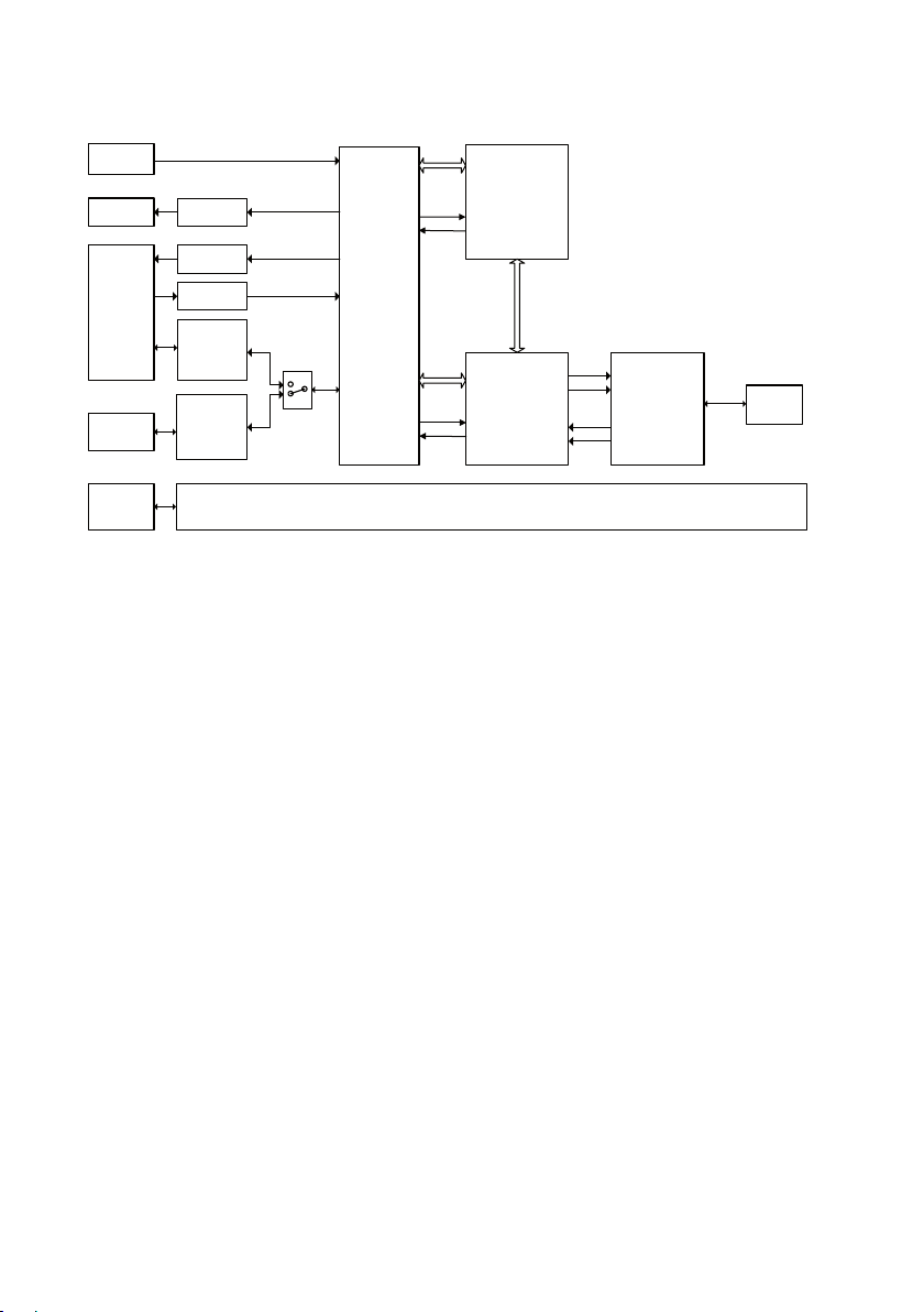
2-pin
screw
terminal
LED’s LED driver
RS-232
Drivers
and
protection
Drivers
and
protection
RS-485
9-pin
screw
terminal
I/O
Output
ARM7
Processor
V34 Single
Chip Modem
ISDN
Controller
Isolated Power supply
ISDN S
0
Network
Interface
RJ-45
DIP
switches
9-pos
D-Sub
I/O Input
Functional description
Page 9

9
6620-2200
Remote configuration
The IDW-90 can be configured from a remote modem. To configure a IDW-90 any GSM ,
ISDN or PSTN modem can be used.
The modem used to configure is referred as “local modem”. Enable remote config by
setting DIP switch 4:7.
Please make sure that the remote IDW-90 is connected to the ISDN network and is
powered up.
… Connect the local modem to it’s media (ISDN, PSTN or GSM)
… Connect the PC’s com-port to the DTE interface of the local modem.
… Connect the power supply.
… Start a terminal emulation program (i.e. Windows Hyper-Terminal)
… Configure the local modem protocol
1. If local modem is a GDW-11/12 a normal GSM data connection should be used.
2. If local connection is ISDN, configure with the B channel protocol V110 9600 bit/s
3. If local connection uses some analogue modem, the modem has to be configured for
V32 modulation line speed 9600 bit/s.
… Set up a connection to the remote IDW-90 to be configured by using the normal
dial command: ATD<No><CR>. When connected send the remote escape sequence
<++++>. The called remote IDW-90 shall acknowledges by requesting the remote
password. Please enter the correct password (default: no password, just return). Now
you can configure the remote IDW-90 using AT-commands. Password for remote configuration is defined with AT*WRAP – Remote access password.
… Configure the parameter on the remote IDW-90 from your terminal program and
save the settings with AT&W.
Hang up the connection using the ATH command.
Generic I/O
The generic I/O gives the following functionality:
1. Establishing a data connection to a predefined target number
When the input is switched (pulsed), the modem establish a data connection to
the stored predefined number. After a time, specified in the modem, without data
exchange, the connection is released (inactivity timer).
2. Sending a SMS Message to a predefined targetnumber
When the input is switched (pulsed), the modem shall establish a connection to a SMS
service centre defined by a predefined number. The SMS Messages can handle at least
160 characters. TAP and UCP protocols are supported.
3. Sending a Text Message to a predefined targetnumber
When the input is triggered, the modem will establish a connection to the stored telephone number and transfer a predefined text message.
4. Switch the remote digital output
When the input is triggered, the modem will establish a connection to the stored
number of an remote unit and send out a command, that switches (pulses) the remote
output according to a predefined sequence.
Page 10

10
6620-2200
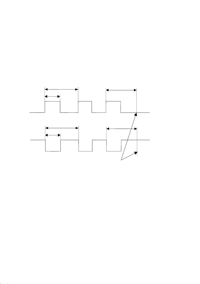
5. Execute AT-Command string
=t
a
High level trigged input timing
≥
t
a
Trig
Trig
=t
a
Low level trigged input timing
≥
t
a
=t
a
<t
a
Execute a pre-programmable AT command string stored in the table of entries.
This can for example be used for switching DTE communication parameters for
online an offline mode by using two entries.
6. Transparent I/O
When the input is triggered, the modem will establish a connection to the stored
number of an remote unit and send out a command, after a connection is established,
the I/O is bi-directional.
To accept any remote generic I/O on a modem the “Remote I/O Enable” DIP switch
must be set “ON”
Digital Output
The digital output gives the following functionality:
1. Output Contact
The modem has an change over relay output (SPDT-contact). The output can be
controlled by a remote modem through Transparent I/O and Output service in the
Generic I/O function. The output can also be programmed to follow the local DCD or
DTR signals.
2. Remote controlled
The output can be programmed to follow a remote modem data input. A remote unit
can also set/reset the output as well as transferring a sequence of set- and resets of
the output.
3. Follow DCD/Network
The output can be programmable to follow the local DCD or DTR signal.
Digital Input
The digital input gives the following functionality:
1. Static input
A static digital level trigged input high or low triggers the Generic I/O. With a level
trigged input only the first entry in the Generic I/O list can be trigged by the I/O input.
The input is trigged when
the selected level has been
stable for ta ms.
A new trig will not occur
until the input has return
to the opposite state an
back again.
Page 11
11
6620-2200
2. Pulsed Input
≥
t
a
≤
T
p
>T
p
≥
t
a
≤
T
p
>T
p
Positive edge trigged input timing
Negativ edge trigged input timing
Number of pulses counted
accumulated here
When input is set to edge trigged pulsed the number of pulses counted selects the
entry to be trigged.
For the pulsing of an input, some timings must be kept.
The input is filtered and pulses shorter than ta is discriminated. The time between
pulses must also be kept shorter than Tp. One other restriction on Tp. Is that Tp.³ 2ta.
When time between pulses exceeds Tp the number of pulses are accumulated and an
entry selected by number of pulses counted.
The parameter ta is also used when output pulsing is selected.
The parameters ta and tP are programmable from 10 ms to 2550 ms.
Page 12

12
6620-2200
Interface specifications
Power “LV”
Rated voltage 12 to 48 VDC
Operating voltage 10 to 60 VDC
Rated current 110 mA @ 12 VDC
Rated frequency DC / AC 48 – 62 Hz
Inrush current I2t 0.22 A2s
Startup current* 0.30 Apeak
Polarity Polarity independent
Isolation to All other ports 3 kVrms 50 Hz 1 min
Connection Detachable screw terminal
Connector size 0.2 – 2.5 mm2 (AWG 24 – 12)
Shielded cable Not required
* External supply current required for proper startup.
Integrated Services Digital Network (ISDN)
Electrical specification ISDN BRI: ITU-T I.430.
Data rate 300 bit/s – 128 kbit/s
Protocol Euro ISDN /DSS1, Leased line B1 / B2
Protection Installation Fault Tolerant (up to ±60 V)
Isolation to Power port 3 kVrms 50 Hz 1 min
Connection RJ-45
Shielded cable Not required
12 to 34 VAC
10 to 42 VAC
55 mA @ 24 VDC
30 mA @ 48 VDC
V.110 asynchronous, HDLC async to sync, HDLC transparent,
Byte transparent X.75- SLP, V.120, X.31 B channel, X.31
D channel, ML-PPP
RS-232 2 kVrms 50 Hz 1 min
RS-485 2 kVrms 50 Hz 1 min
I/O 2 kVrms 50 Hz 1 min
Page 13

13
6620-2200
RS-422/485
Electrical specification EIA RS-485
2-wire or 4-wire twisted pair
Data rate 300 bit/s – 115.2 kbit/s
Data format 7 or 8 data bits, Odd, even or none parity, 1 or 2 stop bits,
Σ 9 – 12 bits
Protocol Transparent
Retiming Yes
Turn around time 50 µs (half duplex)
Transmission range <1200 m, depending on data rate and cable type (EIA RS-485)
Settings 120 W termination and failsafe biasing 680 W
Protection Installation Fault Tolerant (up to ±60 V)
Isolation to Power port 3 kVrms 50 Hz 1 min
ISDN 2 kVrms 50 Hz 1 min
IO 2 kVrms 50 Hz 1 min
Galvanic connection to RS-232
Connection Detachable screw terminal
Connector size 0.2 – 2.5 mm2 (AWG 24 – 12)
Shielded cable Not required*
Miscellaneous Do not connect RS-232 and RS-422/485 simultaneously
* To minimise the risk of interference, a shielded cable is recommended when the cable is located inside 3 m
boundary to the rails and connected to this port.
The cable shield should be properly connected (360°) to an earthing point within 1 m from this port.
This earthing point should have a low impedance connection to the conductive enclosure of the apparatus
cabinet, or similar, where the unit is built-in. This conductive enclosure should be connected to the earthing
system of an installation and may be directly connected to the protective earth.
Page 14

14
6620-2200
RS-232
Electrical specification EIA/TIA-232
Data rate 1 200 bit/s – 115.2 kbit/s
Data format 7 or 8 data bits, Odd, even or none parity, 1 or 2 stop bits;
Σ 9 – 12 bits
Protocol Transparent
Retiming Yes
Transmission range Cable length ≤15 m
Isolation to Power port 3 kVrms 50 Hz 1 min
ISDN line 2 kVrms 50 Hz 1 min
I/O 1.5 kVrms 50 Hz 1 min
Galvanic connection to RS-485
Connection 9-pin D-sub female (DCE)
Shielded cable Not required*
Miscellaneous Do not connect RS-232 and RS-422/485 simultaneously
Generic I/O Input
Electrical specification Opto isolated input
Input voltage range 0 – 60 VDC
Input current 5mA @ 60 VDC
Input inactive
Input active
Uin <2.5 V
Uin >5.0 V
Transmission range Cable Length ≤ 15 m
Connection Detachable screw terminal (DCE)
Connector size 0.2 – 2.5 mm2 (AWG 24 – 12)
Isolation to Power port 3 kVrms 50 Hz 1 min
ISDN line 2 kVrms 50 Hz 1 min
RS-232 2 kVrms 50 Hz 1 min
RS-485 2 kVrms 50 Hz 1 min
I/O output 2 kVrms 50 Hz 1 min
Shielded cable Not required*
* To minimise the risk of interference, a shielded cable is recommended when the cable is located inside 3 m
boundary to the rails and connected to this port.
The cable shield should be properly connected (360°) to an earthing point within 1 m from this port.
This earthing point should have a low impedance connection to the conductive enclosure of the apparatus
cabinet, or similar, where the unit is built-in. This conductive enclosure should be connected to the earthing
system of an installation and may be directly connected to the protective earth.
Page 15

15
6620-2200
Generic I/O Relay Output
Electrical specification One change over contact
Switching voltage Max 40 VAC/DC
Switching current Max 500 mA AC/DC
Electrical endurance 5 x 10⁵ operations @ 20 W / 20 VA Resistive load
Transmission range Cable Length ≤15 m
Connection Detachable screw terminal (DCE )
Connector size 0.2 – 2.5 mm2 (AWG 24 – 12)
Isolation to Power port 3 kVrms 50 Hz 1 min
ISDN line 2 kVrms 50 Hz 1 min
RS-232 1.5 kVrms 50 Hz 1 min
RS-485 1.5 kVrms 50 Hz 1 min
I/O input 2 kVrms 50 Hz 1 min
Shielded cable Not required*
* To minimise the risk of interference, a shielded cable is recommended when the cable is located inside 3 m
boundary to the rails and connected to this port.
The cable shield should be properly connected (360°) to an earthing point within 1 m from this port.
This earthing point should have a low impedance connection to the conductive enclosure of the apparatus
cabinet, or similar, where the unit is built-in. This conductive enclosure should be connected to the earthing
system of an installation and may be directly connected to the protective earth.
Page 16

16
6620-2200
Connections
LED Indicators
(for details
see page 18)
DIP-switches accessible under lid
(for details see page 20–23)
DIP-switch S5
RS-422/485 termination
(for details see page 23)
Position Direction* Description Product marking
1 In AC: Neutral
COM
DC: – Voltage
2 In AC: Line
+VA
DC: + Voltage
Position Direction* Description Product marking
No 1 In R+ (A’) Receive RS-422/485 4-wire R+
No 2 In R– (B’) Receive RS-422/485 4-wire R–
No 3 In/Out T+ (A) Transmit RS-422/485 4-wire
Out T+ (A/A’)
RS-485 2-wire
T/R+
Transmit/Receive
No 4 Out T– (B) Transmit RS-422/485 4-wire
In/Out T+ (A/A’)
RS-485 2-wire
T/R–
Transmit/Receive
Page 17

17
6620-2200
Position Direction* Description
1 – NC
2 – NC
3 Out Transmit +
4 In Receive +
5 In Receive –
6 Out Transmit –
7 – NC
8 – NC
Position Direction* Description
No 1 Out Data Carrier Detect (DCD)
No 2 Out Received Data (RD)
No 3 In Transmitted Data (TD)
No 4 In Data Terminal Ready (DTR)
No 5 – Signal Ground (SG)
No 6 Out Data Set Ready (DSR)
No 7 In Request To Send (RTS)
No 8 Out Clear To Send (CTS)
No 9 Out Ring Indicator (RI)
Position Direction* Description Product marking
No 7 In/Out Normal closed contact NC
No 8 In/Out Common contact C
No 9 In/Out Normal open contact NO
Position Direction* Description Product marking
No 5 In Input + +
No 6 In Input – –
Page 18

18
6620-2200
LED indicators
LED Status Description
L1
ISDN Line status
L2
ISDN Data connection
ANL
Analogue line
DCD
Data Carrier Detect
TD
Transmit Data
RD
Receive Data
RTS
Request to Send
DTR
Data Terminal Ready
See
below
LED normally showing the status of the ISDN
S0 interface. L1 together with L2 is also used
to indicate error conditions in the IDW-90 and
the connection to the ISDN S0 interface.
See
below
LED Normally showing the state of the data
connection
OFF No analogue connection established
BLINK Analogue call in progress
ON Analogue line established
OFF The DCD signal is inactive.
ON The DCD signal is active.The behavior of the
DCD-line is programable, see configuration
command cdcd. Normaly used to indicat an
active connection
LED showing data from the DTE, the LED will
blink when data received
LED showing data transmitted to the DTE, the
LED will blink when data transmitted
OFF RTS signal is inactiveIf used for flow control
this indicates DTE not ready to receive
ON RTS signal is activeIf used for flow control this
indicates DTE ready to receive
OFF DTR Signal from DTE is inactive
ON DTR Signal from DTE is activeThe use of the
DTR signal is programmable, see configuration
command cdtr
Status Description
L1 L2
ON OFF S0 connection OK
ON 1 short blink/s Call setup in progress
ON 1 long blink/s Waiting for B channel synchronization
ON ON Data connection is established
OFF OFF No power or Hardware error
0.5 s ON
OFF No S0 connection
0.5 s OFF
Page 19

19
6620-2200
Configuration
1
11
1
!
All needed configurations and parameter settings are done by the DIP-switches, located
under the top lid of the IDW-90.
S3S4
S2
S1
DIP-switch settings
Before DIP-switch settings:
Prevent damage to internal electronics from electrostatic discharges (ESD) by
discharging your body to a grounding point (e.g. use of wrist strap)
NOTE DIP-switch alterations are only effective after a power on or commands
“AT**loadsw” and “AT**reset”.
A setting configured by any other method during normal operation, overrides
the DIP-switch setting. However, at power up, the DIP-switch settings have
precedence over the setting configured by any other method.
Factory settings
ON
1 2 3 4 5 6 7 8
ON
1 2 3 4
S5
S1
ON
1 2 3 4 5 6 7 8
S2
ON
1 2 3 4 5 6 7 8
S3
ON
1 2 3 4 5 6 7 8
S4
Page 20

20
6620-2200
S1 DIP-switch
Selection of DTE speed
ON
1 2 3 4 5 6 7 8
ON
1 2 3 4 5 6 7 8
ON
1 2 3 4 5 6 7 8
ON
1 2 3 4 5 6 7 8
ON
1 2 3 4 5 6 7 8
ON
1 2 3 4 5 6 7 8
ON
1 2 3 4 5 6 7 8
Auto Baud
300 bit/s
600 bit/s
1200 bit/s
2400 bit/s
4800 bit/s
9600 bit/s
S1 DIP-switch
Selection of DTE format
ON
1 2 3 4 5 6 7 8
ON
1 2 3 4 5 6 7 8
ON
1 2 3 4 5 6 7 8
ON
1 2 3 4 5 6 7 8
ON
1 2 3 4 5 6 7 8
ON
1 2 3 4 5 6 7 8
Use stored values
7E 1S
7O 1S
8N 1S
8E 1S
8O 1S
ON
1 2 3 4 5 6 7 8
ON
1 2 3 4 5 6 7 8
ON
1 2 3 4 5 6 7 8
ON
1 2 3 4 5 6 7 8
ON
1 2 3 4 5 6 7 8
ON
1 2 3 4 5 6 7 8
ON
1 2 3 4 5 6 7 8
ON
1 2 3 4 5 6 7 8
ON
1 2 3 4 5 6 7 8
ON
1 2 3 4 5 6 7 8
ON
1 2 3 4 5 6 7 8
19.2 kbit/s
38.4 kbit/s
57.6 kbit/s
115.2 kbit/s
230 kbit/s
Use stored values
7E 2S
7O 2S
8N 2S
8E 2S
8O 2S
Page 21

21
6620-2200
S2 DIP-switch
DTE flow control
ON
1 2 3 4 5 6 7 8
ON
1 2 3 4 5 6 7 8
ON
1 2 3 4 5 6 7 8
ON
1 2 3 4 5 6 7 8
Use stored values
No flow control CTS is always ON,
RTS ignored AT&K0&R1
No flow control CTS follows DTR,
RTS ignored AT&K0 &R2
No flow control CTS follows changes
on RTS AT&K0&R0
S2 DIP-switch
DTR handling
ON
1 2 3 4 5 6 7 8
ON
1 2 3 4 5 6 7 8
Use stored values
DTR is evaluated:
Ignored. AT&D or AT**cdtr = 0
ON
1 2 3 4 5 6 7 8
ON
1 2 3 4 5 6 7 8
ON
1 2 3 4 5 6 7 8
ON
1 2 3 4 5 6 7 8
ON
1 2 3 4 5 6 7 8
ON
1 2 3 4 5 6 7 8
Hardware flow control
RTS/CTS AT&K3
Software flow control
XON/XOFF
CTS is always ON, RTS
ignored AT&K4&R1
Software flow control
XON/XOFFCTS follows DTR, RTS ignored
AT&K4&R2
Software flow control
XON/XOFF
CTS follows
RTS AT&K4
DTR is evaluated:
Dropping the DTR line
by the DTE will disconnect an existing ISDN
connection.An incoming
call will be accepted only
with DTR active. AT&D2
or AT**cdtr = 2
DTR is evaluated:
Incoming calls will be
accepted independent of
DTR status; DTR drop
disconnects an active
connection. AT&D4 or
AT**cdtr = 4
S2 DIP-switch
RS-485 control
ON
1 2 3 4 5 6 7 8
ON
1 2 3 4 5 6 7 8
S2: 8 not used
RS-232 enable
RS-422/485 disable
RS-485 2 wire enable
RS-232 disable
ON
1 2 3 4 5 6 7 8
RS-422/485 4 wire
enable RS-232 disable
Page 22

22
6620-2200
S3 DIP-switch
B-channel protocol
ON
1 2 3 4 5 6 7 8
ON
1 2 3 4 5 6 7 8
ON
1 2 3 4 5 6 7 8
ON
1 2 3 4 5 6 7 8
ON
1 2 3 4 5 6 7 8
ON
1 2 3 4 5 6 7 8
Use stored values
V.110 asynchronous
V.110 configured for GSM
HDLC asynchronous to synchronous
conversion (for PPP asynchronous and
single link PPP)
HDLC transparent (DTE data octets
packed into HDLC frames)
Byte transparent (raw B-channel data)
S3 DIP-switch
Command interface
ON
1 2 3 4 5 6 7 8
ON
1 2 3 4 5 6 7 8
ON
1 2 3 4 5 6 7 8
Use stored values
AT-command set
Hot line DTR call
ON
1 2 3 4 5 6 7 8
ON
1 2 3 4 5 6 7 8
ON
1 2 3 4 5 6 7 8
ON
1 2 3 4 5 6 7 8
ON
1 2 3 4 5 6 7 8
ON
1 2 3 4 5 6 7 8
ON
1 2 3 4 5 6 7 8
X.75-NL
7 V.120 asynchronous
O 2S
X25 / X31 B channel
(X.25 B channel)
X25 / X31 D channel
ML-PPP Multilink PPP
Hot line TxD call
Connect always
S3: 8 not used
Page 23

23
6620-2200
S4 DIP-switch
D-channel protocol
ON
1 2 3 4 5 6 7 8
ON
1 2 3 4 5 6 7 8
Use stored values
ISDN D-channel protocol
DSS1 AT**isdn=0
S4 DIP-switch
Local echo
ON
1 2 3 4 5 6 7 8
Use stored values
S4 DIP-switch
Result code handling
ON
1 2 3 4 5 6 7 8
ON
1 2 3 4 5 6 7 8
Use stored values
Suppress result codes,
quiet mode, ATQ1
S4 DIP-switch
D-channel protocol
ON
1 2 3 4 5 6 7 8
Use stored values
ON
1 2 3 4 5 6 7 8
ON
1 2 3 4 5 6 7 8
ON
1 2 3 4 5 6 7 8
ON
1 2 3 4 5 6 7 8
ON
1 2 3 4 5 6 7 8
Leased line using channel
B1 AT**isdn=12
Leased line using channel
B2 AT**isdn=13
Disable Local echo, ATE0
Numeric result codes,
ATV0
Enable remote
configuration
S4 DIP-switch
D-channel protocol
ON
1 2 3 4 5 6 7 8
S5 DIP-switch
Termination
ON
1 2 3 4
ON
1 2 3 4
No termination
Termination of both T and R
in 2-wire connection
Use stored values
ON
1 2 3 4
ON
1 2 3 4
ON
1 2 3 4 5 6 7 8
Disable automatic
selection between
ISDN and PSTN
Termination of R in 4-wire connection
Termination of both T and R in 4-wire connection
Page 24

24
6620-2200
=Termination
IDW-90
Slave unit Slave unit Slave unit
IDW-90
Slave unit Slave unit Slave unit
Max 0.3 metre
=Termination
T+
T–
T+ T- T+ T- A B
R+
R–
T+
T–
R– R+ R+ T– T– B’ A’ B A T+ T+ R–
RS-422/485 general advice
Termination recommendations
The RS-422/485 line must be terminated. In the TD-36 485, the termination is combined
with fail-safe functionality.The termination is used to prevent undefined states when the
bus is in tri-state condition.
… Using 2-wire RS-485 both ends should be terminated.
… Using 4-wire RS-485 both pairs shall be terminated at both ends.
… Using 4-wire RS-422 it’s only necessary to terminate the receivers.
RS-422/485 connection pins can be differently named. For some equipment brands
the T+ corresponds to A, but other brands might use some other naming convention.
If a unit does not work it can help to swap A and B.
Page 25

25
6620-2200
Mounting
CLICK!
This unit should be mounted on 35 mm DIN-rail, which is
horizontally mounted inside an apparatus cabinet, or similar.
Snap on mounting, see figure.
Cooling
This unit uses convection cooling. To avoid obstructing the airflow around the unit, use the following spacing rules. Minimum
spacing 25 mm (1.0 inch) above /below and 10 mm (0.4 inches)
left /right the unit. Spacing is recommended for the use of unit
in full operating temperature range and service life.
10 mm *
(0.4 inches)
25 mm
* Spacing (left/right) recommended for
full operating temperature range
Removal
Press down the black support at the top of the unit. See figure.
25 mm
Page 26

26
6620-2200
Windows configuration tool TD-Tool
The ID-Tool is a PC – application program with a graphical interface for easy
configuration of the complex functions found in the IDW-90.
Please refer to TD-Tool for a complete description of the functionality of the
Windows program.
Configuration
The IDW-90 can be configured both from the local DTE interface and remotely over the
ISDN network. Independently if the local or remote interface is used the configuration
can be made with AT-commands or with a PC-based application configuration tool.
Basic configurations can also be made with DIP-switches locally.
AT-Commands
The most commonly used commands are listed below in short format
Please refer to the document “IDW-90 AT-Command Guide” for a complete list of all the
available AT-commands and a detailed description of the serial AT-command interface.
A – Answer a call
Syntax: ATA
**br – Fixed DTE rate
Syntax:
AT**br=<n>
AT**br=?
AT**br
Parameters:
<n>:
0: Autobauding, (automatic local bit rate adaption) (default)
1: 1 200 bit/s
2: 2 400 bit/s
3: 4 800 bit/s
4: 9 600 bit/s
5: 19 200 bit/s
6: 38 400 bit/s
7: 57 600 bit/s
8: 115 200 bit/s
9: 230 400 bit/s
20: 300 bit/s
21: 600 bit/s
Page 27

27
6620-2200
&C –DCD Option
Syntax:
AT&C<n>
Parameters:
<n>
0: DCD always ON
1: DCD indicates a connection (default)
2 DCD follows DTR
3: DCD indicates link level established (X.31-D only)
**cmds – Command set
Syntax:
AT**cmds=<n>
Parameters:
<n>
0: AT command set (default)
6: Automatic dialling when DTR is set
7: Automatic dialling when TxD is received by the IDW-90
8: Automatic dialling always connect
10: IDW-90+Configurator
12: Incoming calls only
D and DL – Dial command
Syntax:
ATD<nb> where <nb> represents a dial string composed of dial characters and dial
modifiers.
Page 28

28
6620-2200
&D – DTR Control
Syntax:
AT&D<n>
Parameters:
<n>
0: The DTR signal is ignored (Default)
2: Upon DTR switch from ON to OFF, the call is hang up.
DTR need to be high to accept incoming calls. (Default)
4: Upon DTR switch from ON to OFF, the call is hang up DTR doesn’t affect
incoming calls accepted .
**dabort – Dial abort
Syntax:
AT**dabort=<n>
Parameters:
<n>
0: Dialling will not be aborted by incoming characters.
1: Characters from DTE aborts dial during the connection process (default).
**dbits – Asynchronous databits
Syntax:
AT**dbits=<n>
AT**dbits=?
AT**dbits
Parameters:
<n>:
7: Set format to 7 databits
8: Set format to 8 databits
E – Echo
Syntax:
ATE<n>
Parameters:
<n>
0: Characters are not echoed
1: Characters are echoed
Page 29

29
6620-2200
&F – Restore Factory Configuration
Syntax:
AT&F<n>
Parameters:
<n>
0: Setup all parameter concerning data port.
1: Setup all parameter including ISDN protocol and msn settings.
H – Disconnect (Hang-Up)
Syntax:
ATH<n>
Parameters:
<n>
0: The modem will release the line if the modem currently is on-line.
1: If on-hook, the modem will go off-hook and enter command mode.
&K – DTE-DCE flow control
Syntax:
AT&K<n>
Parameters:
<n>
0: Disables Flow Control (Default).
3: Enables RTS/CTS flow control in data mode.
4: Enables XON/XOFF.
5: Enables RTS/CTS flow control in data and command mode.
Page 30

30
6620-2200
!+MS – Select Modulation for analogue connections
Syntax:
+MS=<carrier>,<automode>,<min_tx_rate>,<max_tx_rate>,<min_rx_rate>,<max_rx_rate>
+MS= ?
+MS ?
Parameters:
<carrier>
B103 300 bit/s
B212 1200 bit/s
V21 300 bit/s
V22 1200 bit/s
V22B 1200 or 2400 bit/s
V23C 1200 bit/s
V32 4800 or 9600 bit/s
V32B 4800, 7200, 9600, 12000 or 144400 bit/s
V34 2400, 4800, 7200, 9600, 12000, 14400, 16800, 19200, 21600, 24000, 26400, 28800,
31200, 33600, 33600 bit/s
<automode>
0: Disable
1: Enable
< min_xx_rate >, < max_xx_rate >
Minimum and maximum data rate depending on modulation used.
**prty – Asynchronous parity
Syntax:
AT**prty=<n>
AT**prty=?
AT**prty
Parameters:
<n>:
0: No parity
1: Set even parity
2: Set odd parity
Page 31

31
6620-2200
Q – Result Code Control
Syntax:
ATQ<n>
Parameters:
<n>
0: DCE transmits result codes
1: Result codes are suppressed and not transmitted
S0 – Automatic answer
Syntax:
ATS0=<value>
Parameters:
<value>
0 Disable auto answer
1–255 Rings to answer on
V – Result format
Syntax:
ATV<n>
Parameters:
<n>
0 (Information responses): <text><CR><LF><CR><LF><numeric code><CR>
0 (Result codes): <numeric code><CR>
1 (Information responses): <CR><LF><text><CR><LF>><verbose code><CR><LF>
1 (Result codes): <CR><LF><verbose code><CR><LF>
Page 32

32
6620-2200
W – Connect message control
Syntax:
ATW<n>
Parameters:
<n>
0: Shows result code (RING, CONNECT) without additional info (default).
1: Result is presented with extended result codes. RING and CONNECT including
ISDN address, all others include error causes. Message RINGING will be displayed
with an outgoing call.
&W – Store system setting
Syntax:AT&W<n>
Parameters:<n>
0: Store the current configuration as profile 0
1: Store the current configuration as profile 1
Page 33

33
6620-2200
… IDW-90 connected to IDW-90 with DTR signal call
DTR
DSR
DCD
ISDN
Network
Configure the units
AT&F0
AT&F1
AT&W Store default settings
Set the unit to factory default
Set up the connection – The dialling modem
AT**catab1=nnn Store the number of the remote modem in the automatic
AT**cdsr=0 Set DSR signal always high (if this signal is used to trig the
AT**isdn=6 Activates automatic DTR dialling if DTR switches from low
AT**save Save settings
Switch DTR from OFF to ON The modem will now dial the phone number stored in the
calling table of IDW-90
DTR)
(OFF) to high (ON).
first location of the automatic calling table
Set up the connection – The answering modem
ATA Enter the answer command when RING comes from the net-
work or set up ATS0=1 to auto answer on 1 RING signal
(or more than 1).
Relay
10 kohm
May be required in harsh environments
External
application
Page 34

34
6620-2200
… Frequently used settings for PLC-systems
ISDN
Network
Most PLC-systems and other industrial applications where modems are used, require the
same changes to default settings.
The most commonly encountered problems concern speed, parity and control signals
from the connected equipment.
Speed and parity are changed with the switches under the cover in block S1. If this action
does not solve the problem the modem’s answering codes and possible echoing of commands might be the source of the difficulty.
Below follows a list of commands that might resolve the problems. The commands may of
course be placed on one single command line if desired.
Configure the IDW-90 connected to the PLC
AT&F0 Set the unit to factory default
ATV0 Gives the answering codes in short format. (digits)
ATQ1 No result codes are sent on the RS-232/V.24 connection.
ATE0 Commands that are sent from the terminal/computer etc. are not echoed
AT&C1 DCD will follow the carrier on the line.
AT&K0 No handshaking.
at**dabort=0 Character abort option OFF
AT&W Save settings
back to the RS-232/V.24 connection.
Page 35

35
6620-2200
… Leased line connection
Leased Line
To set the adapter for leased line applications use the dipswitches.
Configure the units
at**defa=0 Set the unit to factory default
ATQ1 No result codes are sent on the RS-232/V.24 connection.
AT&W Store default settings
S1 Set DTE speed and format
S4:1 ON or OFF
S4:2 ON
S4:3 OFF
S3:1 OFF
S3:2 OFF
S3:3 ON
S3:4 OFF
S3:5 OFF
S3:6 OFF
S3:7 ON
To make the setting active the power must be cycled OFF -> ON.
Selects leased line, using channel B1 or B2
Sets B-channel protocol to HDLC transparent
Sets connections behaviour to Connect always
Page 36

36
6620-2200
… IDW-90 – Secure Call-back
ISDN
Network
PSTN
Network
The IDW-90 is connected to a PLC which one want to restrict access to. The IDW-90
can support access control through the Secure Callback function. In this example password and callback to a predefined number is chosen. The modem in the calling end is
here chosen to be a PSTN modem, but can be any of the PSTN, ISDN or GSM modem
from the Westermo product range.
The DTE serial speed between the PLC – IDW-90 and TDW-33 – PC is assumed to be
9600 8N1 but can be chosen to fit the actual system requirement.
Configure the IDW-90
at**defa=0
at**defa=1
at**br=4 DTE baudrate 9600
ATS0=1 Auto answer after first ring
ATQ1E0&C1&K0
at**dabort=0
AT&W Save settings
AT*WCB=4 Callback enabled, Password and callback
AT*WCBTAB=1,”+4670428000”,”n3Y9kA6otYZu8” Define callback number and password
AT*WCBTIME=10 Define delay time between hangup an
Set the unit to factory default
Suitable for PLC communication,
see section Frequently used settings for
PLC-systems
number stored in one or more positions
of wcbtab
in position 1
When the password is entered number
+4670428000 will be called.
callback
The IDW-90 will wait 10 s after hangup to
callback to allow the analogue modem to
hangup
Configure the TDW-33
AT&F Set the unit to factory default
AT+IPR=9600 DTE baudrate 9600
AT+ICF=3,4 Character framing 8 data, 1 stop, parity none
ATS0=1 Auto answer after first ring
AT&W Store default settings
Page 37

37
6620-2200
Set up the connection
The dialling
modem TDW-33
ATD0705123456 IDW-90 answers the cal-
CONNECT 9600
Password: n3Y9kA6otYZu8
NO CARRIER Wait 10 s The connection is
CONNECT 9600 IDW-90 dials
CONNECT 9600 Connection is established between the
The answering
modem IDW-90
land requests the password from TDW-33
IDW-90 verifies the
password to the passwords stored and if true
compare dissconnects.
+4670428000
Comment
Dial the number to IDW-90
Operator/system at TDW-33 enters
Password: n3Y9kA6otYZu8
broken and TD-36 waits the programmed
10 s for TDW-33 to disconnect
The number programmed corresponding
to the password is dialled, preferable it’s
the number to the TDW-33
PC at TDW-33 and the PLC at IDW-90
Page 38

38
6620-2200
… IDW-90 sending text message with SMS by usage of Generic I/O
5 – 48 V
Trigging SMS no 2
SMS-server
Mobile phone
PLC
Trigging SMS no 3
GSM
Network
ISDN
Network
Configure a IDW-90 to send different SMS depending on the I/O input pulse train.
Page 39

39
6620-2200
Configure the IDW-90
at**defa=0
at**defa=1
AT&W Store default settings
AT*WIOP=5,10,2,3,0 Set I/O params
AT*WIOL=2,2,0,0,0,num1,text1,num2,1 Set I/O list entry 2
AT*WIOL=3,2,0,0,0,num3,text2, num4,1 Set I/O list entry 3
Set the unit to factory default
Min pulse time = 50 ms (5)
Max pulse time = 100 ms (10)
Trig type = Pulsed trigged (2)
Pulse trig type = POS, pos edge (3)
Output type = No output (0)
Entry = 2 (2)
Service = SMS (2)
Retry = NO (0)
Timeout = 0
Priority = 0
Data 1 = SMS receiver number (num1)
Data 2 = SMS text (text1)
Data 3 = Service center Adress (num2)
Data 4 = SMS protocol UDP (1)
Entry = 2 (2)
Service = SMS (2)
Retry = NO (0)
Timeout = 0
Priority = 0
Data 1 = SMS receiver number (num3)
Data 2 = SMS text (text2)
Data 3 = Service center Adress (num4)
Data 4 = SMS protocol UDP (1)
Send message
I/O input pulsed with two pulses SMS message text1 transferred to receiver num1
I/O input pulsed with three pulses SMS message text2 transferred to receiver num3
Testing by simulating the event
AT*WIOT=2 Force sending of SMS-message at entry 2
AT*WIOT=3 Force sending of SMS-message at entry 3
Page 40

IDW-90
Te rmination
1
2
… IDW-90 two wire half duplex
ISDN
Network
In this application the IDW-90 is set to communicate with a number of units with RS-485
interface. The communication is 2 wire half duplex at 38 400 bit/s, 8 data, parity even and
1 stop bit.
Configure the IDW-90
at**defa=0at**defa=1 Set the unit to factory default
AT&W Store default settings
S2:6 ON RS-422/485 enable RS-232 disable
S2:7 OFF Select 2-wire RS-485
S1:4 ON 38.4 kbit/s
S1:7 ON 8data bits even parity 1 stop bit
To make switch setting active the power must be cycled OFF -> ON.
40
6620-2200
Page 41

Westermo • SE-640 40 Stora Sundby, Sweden
Tel +46 16 42 80 00 Fax +46 16 42 80 01
Sales Units
Westermo Data Communications
E-mail: info@westermo.com
www.westermo.com
China
sales.cn@westermo.com
www.cn.westermo.com
France
infos@westermo.fr
www.westermo.fr
Germany
info@westermo.de
www.westermo.de
For complete contact information, please visit our website at www.westermo.com/contact
REV.F 6620-2200 2014-04 Westermo Teleindustri AB, Sweden – A Beijer Electronics Group Company
North America
info@westermo.com
www.westermo.com
Singapore
sales@westermo.com.sg
www.westermo.com
Sweden
info.sverige@westermo.se
www.westermo.se
or scan the QR code with your mobile phone.
United Kingdom
sales@westermo.co.uk
www.westermo.co.uk
Other Offices
Page 42

42
6620-2200
Page 43

43
6620-2200
Page 44

44
6620-2200
 Loading...