

Page 1

ISDN
Terminal Adapter
INSTALLATION MANUAL
6607-2204
www.westermo.com
ID-90 HV/LV
V. 9 0
©
Westermo Teleindustri AB • 2000 • REV.A
Galvanic
Isolation
Transient
Protection
Balanced
Transmission
CE
Approved
9
8
7
6
5
4
3
2
1
Page 2

2
6607-2204
TABLE OF CONTENTS
Introduction ........................................................................................................................................................... 4
Safety
........................................................................................................................................................................ 4
Specifications
........................................................................................................................................................ 5
Installation
..............................................................................................................................................................
6
RS-232/V.24 Connections
.................................................................................................................... 6
RS-422/485 interface
.............................................................................................................................. 7
ISDN S0interface
.................................................................................................................................... 8
Typical S0-bus connections
........................................................................................................... 8–9
Alarm inputs
............................................................................................................................................ 10
LED Indicators
.................................................................................................................................................. 11
DIP-Switch Setup
.................................................................................................................................... 12–18
AT command set
....................................................................................................................................... 19–39
S-registers
......................................................................................................................................... 40–45
AT result codes
............................................................................................................................... 46–48
X.3 PAD
............................................................................................................................................................... 49
Command set – integrated PAD
..................................................................................................... 49
Parameter of the integrated PAD
........................................................................................... 50–57
ISDN access control
....................................................................................................................................... 58
User to User Signalling UUS1
................................................................................................................... 59
Sub addressing
................................................................................................................................................... 60
“Hotline” call
..................................................................................................................................................... 60
Using Multilink PPP
....................................................................................................................................... 61
Details on Multilink PPP
................................................................................................................... 61
Call Bumping
.......................................................................................................................................... 62
Bandwidth on demand (“BOD”)
.................................................................................................... 62
X.25 address translation table
..................................................................................................................... 62
Page 3

36607-2204
X.25 D channel rerouting
.............................................................................................................................
63
Alarm Input settings
....................................................................................................................................... 64
TA+Configurator command set
......................................................................................................... 65–85
Configuring the ID-90 with AT commands
............................................................................... 65
Configuring the ID-90 with X.3 PAD
.......................................................................................... 65
Configuration using the TA+Configurator commands (remote)
...................................... 66
Remote access control
........................................................................................................................ 67
List of TA+Configurator commands
............................................................................................ 67
Block diagram
................................................................................................................................................... 86
Application examples
............................................................................................................................. 87–91
Diagnostic and error messages
........................................................................................................ 92–110
Error messages from AT command set
......................................................................................... 92
ISDN causes and their explanation (DSS1)
....................................................................... 92–93
X.25 diagnostic codes
................................................................................................................. 94–97
X.25 causes in Reset packet
.............................................................................................................. 97
X.25 causes in Clear packet
............................................................................................................... 98
X.25 causes in Restart packet
........................................................................................................... 98
Capi causes and their explanation
.......................................................................................... 98–99
Diagnostic using the internal Trace
............................................................................................ 100–102
Call logging
..................................................................................................................................................... 103
Diagnostic using V90 chipset status report
............................................................................ 104–109
Example Modem Response and Usage
............................................................................................... 110
Software update
............................................................................................................................................. 111
Glossary
.................................................................................................................................................. 112–121
FAQ/Hints
......................................................................................................................................................... 121
Page 4

Introduction
The Westermo ID-90 is an industrialised ISDN Terminal adapter. This Terminal adapter
has been developed with high speed industrial data communications in mind and has some
features you would not expect to find on normal adapters.
The unit is DIN rail mounted and has both an RS-232/V.24 and RS-485 interface in 2 or 4
wire connections.
Terminal data rates of up to 115.2 kbit/sec can be handled with a 128 kbit/s ISDN
B-channel bit rate.
The ID-90 has been designed to meet the European ISDN standard DSS1 as well as French
VN4. All standard ISDN transport protocols are supported including HDLC transparent, X75,
PPP and ML-PPP.
V.110 asyncronous is supported with flow control at data rates up to 19.2 kbit/sec.
A watchdog facility continually monitors the power supply and internal hardware as well
as the operational software. In the event of a problem the modem automatically resets.
This feature has been included to make the unit more suitable for use in unmanned locations.
The ID-90 is available in two standard versions:
One for high input voltages, version HV with nominal voltage range 95–240V AC and
110–240V DC ±10%.
One low voltage version, version LV with nominal input voltages 12–45V AC and
12–55V DC ±10%.
The ID-90 has 4 Alarm inputs that can be used to trigger 20 character SMS paging messages or establish automatic data connections, making the unit ideal for alarm monitoring
and remote diagnostics.
The ID-90 features DIP-switch configuration and can be programmed using AT-commands, and a Configurator for local as well as remote configuration and CAPI 2.0
compatibility.
The ID-90 is also available in an optional configuration with an internal analogue V90
modem enabling connections from ISDN to analogue modem end locations.
The ID-90 has been designed with the engineer in mind, hence the extensive information on
the command set, S registers, DIP-switches and error codes. We have endeavoured to
include all necessary information however if you need more please do not hesitate to call us.
Safety
This equipment should only be installed by professional service personnel. If the unit is
intended for permanent connection to mains supply, there should be a readily accessible
disconnect device (circuit breaker) incorporated into the fixed wiring.
The ID-90 ISDN S0 is compliant to the requirement for TNV1 circuits for connection to
Telecommunication networks. The mains connection is classified as hazardous voltage
and the ID-90 classified as a Class I equipment.
The supply voltage to the Alarm input must use a SELV classified voltage source.
The RS-232/V.24 and RS-485 interface must only be connected to SELV circuits.
Description of the above classifications are given in SS-EN 60950 Issue 5.
The mains input is protected with a 1A, 250V time lag fuse. The fuse must only be replaced
with the same type and rating. Wickman type no: 19372 1A/250V or Littelfuse
®
664 001.
4 6607-2204
Page 5

56607-2204
Specifications
Transmission Interface 1 Asynchronous, full/half duplex or simplex
PPP and ML-PPP Asynchronous & Synchronous
conversion
V110 Asynchronous adaptation up to 19.2 kBit/s
Interface 2 B-channel protocols
V.110 async,V.120 async.
HDLC async. to sync. HDLC transparent
HDLC transparent
Byte transparent
X.75 SLP
X.25 B-Channel
T.70NL and T.90NL
PPP and ML-PPP
D-channel protocols
Euro ISDN DSS1 and French VN4
X.31 Case B D-Channel
Interface 1 RS-232/V.24 9-pin D-sub female. RS-422 and
RS-485 2- and 4-wire with screw terminals
Interface 2 RJ-45
Transmission speed Interface 1 Up to 115.2 kbit/s
Interface 2 Up to 128 kbit/s
Command interface Interface 1 AT-command
Configurator remote/local
X3 PAD
Hotline DTR,TxD,Alarm call.
Alarm inputs Supply
voltage 10–60 V DC 1mA/input @ 10V DC
Power supply HV-version 95–240 V AC, 110–240V DC ±10%
LV-version 12–45 V AC, 12–55V DC ±10%
Power consumption HV-version 0.02A, 1.6W
With V90 option 0.05A, 3.5W
LV-version Max 0.1A, 1.2W
With V90 option 0.25A, 3.0W
Isolation S0Interface 1 500 V AC
Alarm 500 V AC
Mains 3 000 V AC
Indicator LED's TD, RD, DCD, RTS, L1, L2,ANS,ANL
Temperature 5–50°C ambient temperature
Humidity 0–95% without condensation
Dimensions 55x100x128 mm (WxHxD)
Weight 0.4 kg
Mounting 35 mm DIN-rail
Page 6
6
1234567
8
9
110-240 VDC
95-240 VAC
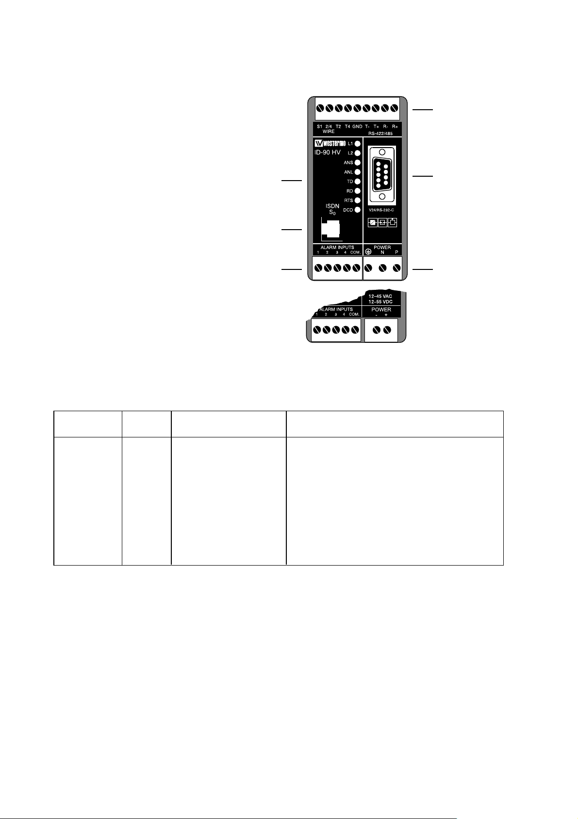
Installation
The Terminal Adapter should be connected in the following way:
Power connection is made through screw-block
at bottom right corner.
For HV-version a 3-pole connector,
and for LV-version a 2-pole connector is used.
Computers or other equipment
are connected through an
RS-232/V.24 or RS-485 connection. The RS-232/V.24 uses a
9-pole D-sub and the RS-485
a 9-pole screw connector.
Do not use ribbon cable
for RS-232/V.24 connections.
Light emit-
ting diodes
Screw-block
for RS-422/485
connection
9-pole D-sub
for RS-232/V.24
connection
Power
connection
Line connec-
tion RJ-45
Alarm
connection
▼ ▼ ▼
▼
▼
▼
RS-232/V.24 Connections
Pinouts for the 9-pole D-sub
O 1 109 DCD/Data Carrier Detect
O 2 104 RD/Received Data
I 3 103 TD/Transmitted Data
I 4 108/2 DTR/Data Terminal Ready
– 5 102 SG/Signal Ground
O 6 107 DSR/Data Set Ready
I 7 105 RTS/Request to Send
O 8 106 CTS/Clear to Send
O 9 125 RI/Ring Indicator
Signal description
I = input O = output on ID-90
Direction
Pin
no.
CCITT V.24
Description
6607-2204
ID-90 LV
Page 7

I 1 R+ (A’) ID-90 Receive
I 2 R– (B’) ID-90 Receive
I/O 3 T+ (A) ID-90 Transmit, at RS-485
I/O 4 T– (B) ID-90 Transmit, at RS-485 Bidirectional
– 5 Shield If shielded cable is used, connect the shield
only at one end to avoid ground currents.
– 6 T4 Termination 4-wire, connect to terminal 2
to terminate a 4-wire connection.
– 7 T2 Termination 2-wire, connect to terminal 3
to terminate a 2-wire connection.
– 8 2-/4-wire 2/4 wire input selector. Input open selects
2-wire and connected to terminal 9 for 4-wire.
– 9 S1 Select 1.Wired to terminal 8 when 4-wire con-
nection is used. Internally connected to +5V
via pull-up resistor.
76607-2204
I = input O = output on ID-90
The definations R+/R–,T+/T– can be various between different manufactures.
ID-90 uses the defination that in a “MARK”-condition R+/T+ is more negative than R–/T–.
Description
Direction
Terminal
Name
RS-422/485 interface connection
The ID-90 is supplied with a RS-422/485 interface.
The RS-422/485 interface is internally in parallel to the RS-232/V.24 interface using the
9-pole D-sub. The two interfaces can not be used or be connected simultaneously, but the
interface connected will automatically be selected as the DTE source.
The RS-422/485 connections are made as shown below. Please note that the selection
of 2- or 4- wire and termination or no termination is done by linking between some of the
screw terminals.
Termination
4-wire
Termination
2-wire
4-wire
Connection
of RS-422
Connection
of RS-485
1234567
8
9
1234567
8
9
1234567
8
9
1234567
8
9
Page 8

8 6607-2204
Typical S0-bus connections
The Terminal equipment TE/TA like the ID-90 Terminal adapter can be connected to the
NT in 3 different ways always with a terminating resistor TR in each end of the bus, TR
should in all three cases be 100 ohm:
• Point to Point. In this configuration the ID-90 is the only TA on the S0bus.
A distance d1 of 1000 m is generally archived with a 0.3 mm
2
40 nF/km cable.
• Short Passive Bus. The short passive bus puts no restriction on the distance between
units, but only specifying the maximum round trip delay to be 10 to 14 µs giving a d1
of 100 to 200 m depending on the cable impedance. Up to 8 ID-90 in combination with
other terminal equipment can be connected to the S0bus with a maximum connection
length d2 = 10 m.
1234567
8
9
TR TR
TA NT
ID-90
1234567
8
9
ID-90
d
2
d
1
GR 4 Fax
1234567
8
9
ID-90
TA TE
NT
TA
Point to Point Configuration
Short Passive Bus
Max 8 TA/TE
TR TR
d
1
ISDN S0interface
The ISDN S0interface is connected via a 8-pol RJ-45 connector.
Pin Function
number
3 Transmit +
4 Receive
5 Receive
6 Transmit
1, 2, 7, 8 No connection
1
2
34
5678
Page 9

96607-2204
• Extended Passive Bus. The difference between the short passive bus and the extended
passive bus is that the extended passive bus specifies a distance between the units, d3 and
that the units are located at the far end from the NT at a distance of d3 from the far end
terminating resistor TR. The range of d3 is from 25 to 50 m giving at least d1 =500 m.
(d2 see Short Passive Bus).
Diagram specifies practically achievable cable lengths as function
of cable capacitance for a 0.3 mm
2
wire.
ID-90
d
2
d
1
d
3
GR 4 Fax
1234567
8
9
ID-90
TA TE
NT
TA
Extended Passive Bus
Max 8 TA/TE
TR TR
Cable capcitance [pF/m]
8
1234567
9
Page 10

10 6607-2204
Alarm inputs
The four alarm inputs are accessed through screw terminals, the alarm inputs are opto-isolated from all other parts of the ID-90. The alarm inputs need an external supply voltage of
10–60V DC to be operated. The supply is connected between the alarm input common and
the four inputs via making or breaking contacts. The inputs is not polarity sensitive but all
inputs must use the same common. The alarm inputs can use any mix of making and breaking contacts as the alarm trigger condition is programmable through AT-commands.
Example 1
Alarm through relay contacts.
Example 2
Alarm from a PLC with open collector.
110-240 VDC
95-240 VAC
110-240 VDC
95-240 VAC
10–60V DC
10–60V DC
Page 11

116607-2204
LED Indicators
Indications via LED’s:
L1 ISDN Line status LED normally showing the status of the ISDN S0interface.
L1 together with L2 is also used to indicate error conditions
in the ID-90 and the connection to the ISDN S0interface.
L2 ISDN Data connection LED Normally showing the state of the data connection
ANS Auto answer OFF = ID-90 will reject incoming calls.
ON = ID-90 will respond to incoming calls
ANL Analogue line Only used when V.90 option installed.
OFF = No analogue connection established
BLINK = Analogue call in progress
ON = Analogue line established
TD Transmit Data LED showing data from the DTE, the LED will blink when data
received
RD Receive Data LED showing data transmitted to the DTE, the LED will blink
when data transmitted
RTS Request to Send LED showing the status of the handshake line RTS from DTE,
LED is ON when DTE requests to send data.
DCD Data Carrier Detect LED showing the status of the handshake line DCD from ID-90,
The behavior of the DCD-line is programable, see configuration
command cdcd.
Active states:
L1 L2 Status Action
⊗ Θ 5x1s Start up phase
⊗Ο
Connection to ISDN S0OK ; ISDN ok, no ISDN connection established
⊗∅ Call setup in progress
⊗⊕ Waiting for B channel
synchronization
⊗⊗ Data connection is
established
Error states:
L1 L2 Status
ΟΟ ID-90 NOT OK No power or Hardware error, check
power distribution, send ID-90 for repair
if necessary
Θ 1x1s Ο Connection to ISDN S
0
Check ISDN interface/ -connector
NOT OK
ΟΘ2x1s ID-90 internal RAM error ID-90 repair necessary
ΟΘ1x1s ID-90 internal ROM error Reload Flash firmware, repair ID-90
if necessary
LED Legend:
⊗ ON
∅ Short on, long off Cycle 1 s
⊕ Long on, short off Cycle 1 sec
Θ Continuous blinking: n times every m seconds, (nxms)
Ο Off
Page 12

12 6607-2204
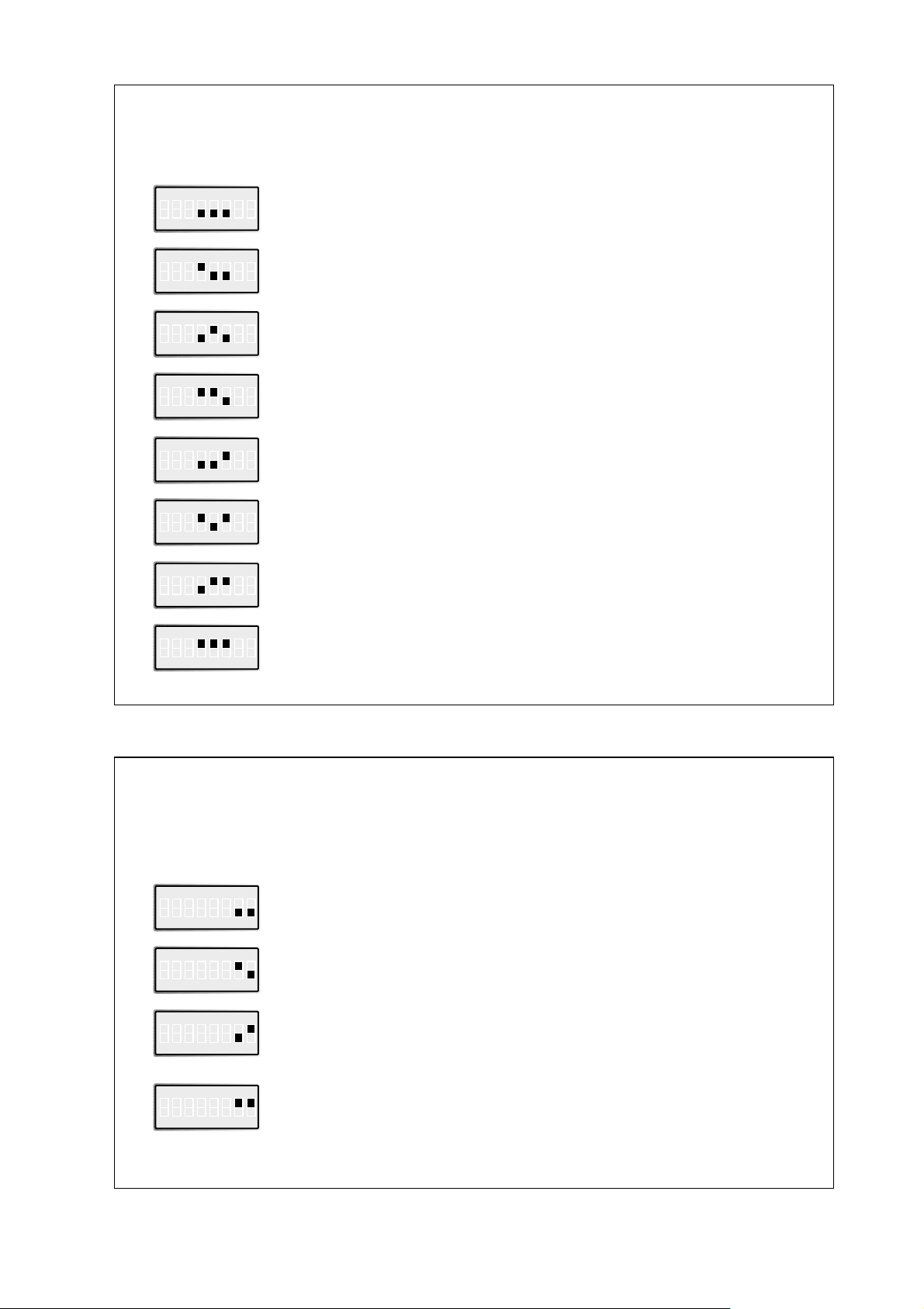
Data bits parity
When using DIP-swithes for parity and data bits
remember to set DTE baudrate switches as well.
DIP-Switch Setup
Disconnect power before changing DIP-switches.
Use ESD-protection when changing switches.
SW:1
SW:3 SW:4
SW:2
1234567
8
9
110-240 VDC
95-240 VAC
Stored setting from ID-90 database is used
S1
–
Related
AT-command
ON
12345678
No Parity 8-data bits
S1
AT**prty=0
AT**dbits=8
ON
12345678
Even Parity 8-data bits
S1
AT**prty=1
AT**dbits=8
ON
12345678
Odd Parity 8-data bits
S1
AT**prty=2
AT**dbits=8
ON
12345678
Not used
S1
–
ON
12345678
Not used
S1
–
ON
12345678
Even Parity 7-data bits
S1
AT**prty=1
AT**dbits=7
ON
12345678
Odd Parity 7-data bits
S1
AT**prty=2
AT**dbits=7
ON
12345678
Page 13
136607-2204
DSR and DCD line control
Stored setting from ID-90 database is used
S1
–
Related
AT-command
ON
12345678
DTR line control
Stored setting from ID-90 database is used
S1
S1
–
Related
AT-command
ON
12345678
ON
12345678
ON
12345678
ON
12345678
ON
12345678
ON
12345678
ON
12345678
ON
12345678
ID-90 control line
DSR and DCD is always ON
S1
AT&S
AT&C
DSR is always ON
DCD ON indicates ISDN connection is established and synchronized
S1
AT&S
AT&C1
DSR ON indicates ISDN connection is established and synchronized
DCD always ON
S1
AT&S1
AT&C
DSR ON indicates ISDN connection is established and synchronized
DCD ON indicates ISDN connection is established and synchronized
S1
AT&S1
AT&C1
ON
12345678
DTR is evaluated: Ignored
AT&D
AT**cdtr = 0
S1
ON
12345678
DTR is evaluated: Dropping the DTR line by the DTE will
disconnect an existing ISDN connection.
An incoming call will be accepted only with DTR active
AT&D2
AT**cdtr = 2
Reserved
S1
–
Reserved
S1
–
DSR and DCD follows DTR
S1
AT**cdsr=2
AT**cdcd=2
S1
ON
12345678
DTR is evaluated: Incoming calls will be accepted independent of
DTR status; DTR drop disconnects an active connection
AT&D4
AT**cdtr = 4
Page 14

14 6607-2204
DTE baudrate
Stored setting from ID-90 database is used
S2
ON
1234
Automatic baud detection
AT%B0
–
Related
AT-command
S2
ON
1234
1 200 bit/s
AT%B1
S2
ON
1234
2 400 bit/s
AT%B2
S2
ON
1234
4 800 bit/s
AT%B3
S2
ON
1234
9 600 bit/s
AT%B4
ON
1234
S2
19 200 bit/s
AT%B5
ON
1234
S2
38 400 bit/s
AT%B6
ON
1234
S2
57 600 bit/s
AT%B7
ON
1234
S2
115 200 bit/s
AT%B8
ON
1234
S2
Page 15
156607-2204
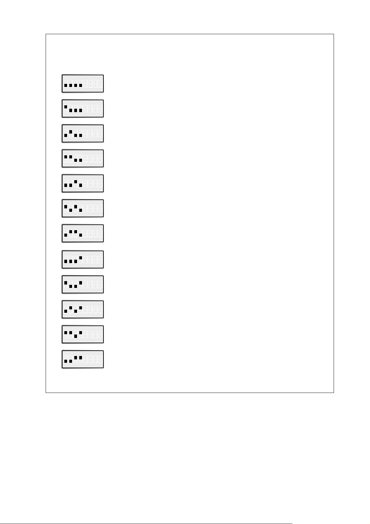
B-Channel protocol
Stored setting from ID-90 database is used
S3
–
Related
AT-command
ON
12345678
V.110 asynchronous
S3
ATB0
ON
12345678
HDLC asynchronous to synchronous conversion
(for PPP asynchronous and single link PPP)
S3
ATB3
ON
12345678
HDLC transparent
(DTE data octets packed into HDLC frames)
S3
ATB4
ON
12345678
Byte transparent (raw B-channel data)
S3
ATB5
ON
12345678
X.75 SLP
S3
ATB10
ON
12345678
V.120 asynchronous
S3
ATB13
ON
12345678
X25 / X31 B channel (X.25 B channel)
S3
ATB20
ON
12345678
X25 / X31 D channel
S3
ATB21
ON
12345678
T.70-NL-CEPT
S3
ATB22
ON
12345678
T.90-NL
S3
ATB23
ON
12345678
ML-PPP Multilink PPP
S3
ATB31
ON
12345678
Page 16

16 6607-2204
Command set
Selects the flow control behaviour of the ID-90 while in data communication phase.
Stored setting from ID-90 database is used
S3
–
Related
AT-command
ON
12345678
AT-command set
S3
AT**cmds = 0
ON
12345678
X.3 PAD
S3
AT**cmds = 1
ON
12345678
Hot line DTR call
S3
AT**cmds = 6
ON
12345678
Hot line TxD call
S3
AT**cmds = 7
ON
12345678
Reserved
S3
–
ON
12345678
Configurator
S3
AT**cmds = 10
ON
12345678
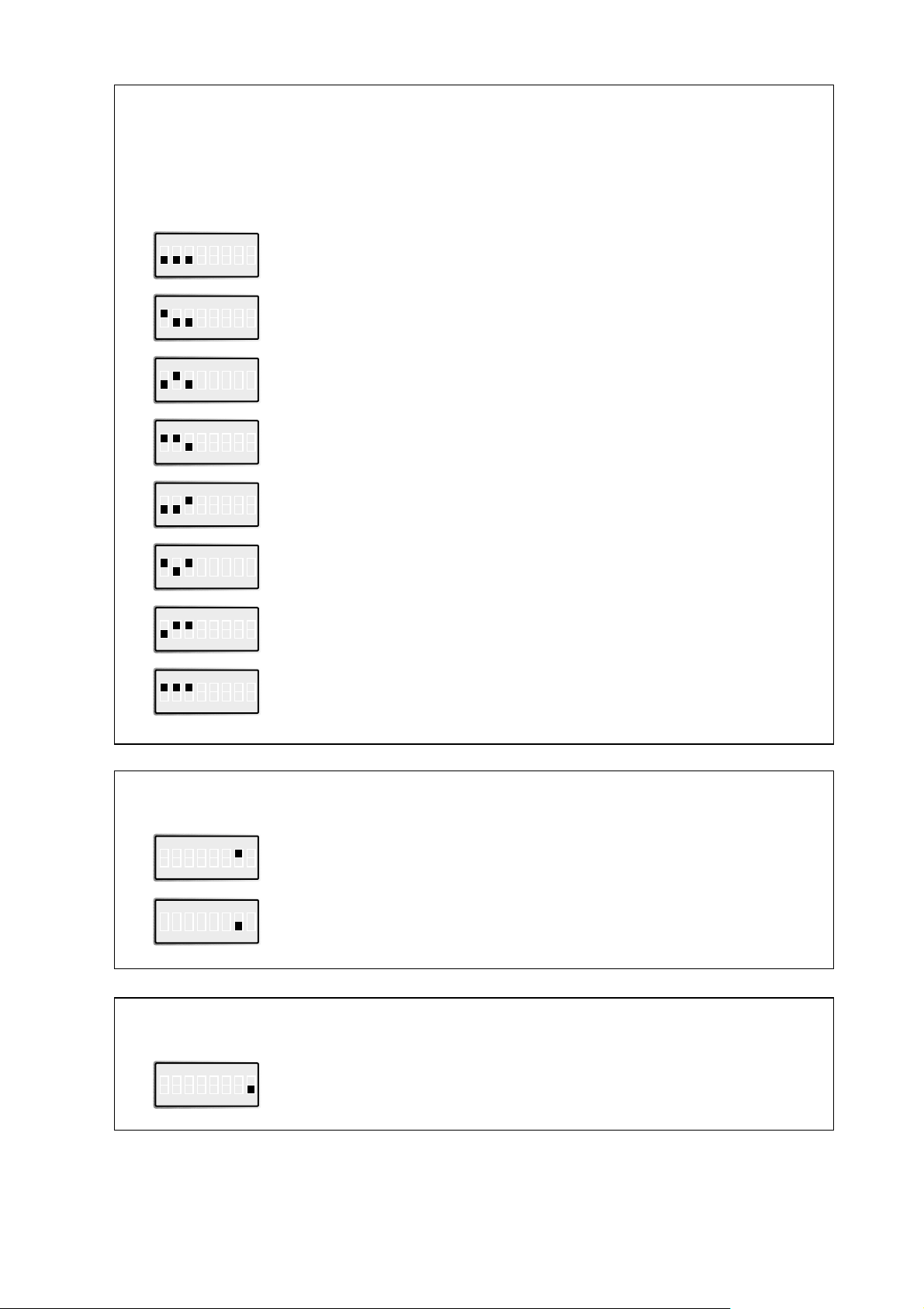
Incomming call handling
Stored setting from ID-90 database is used
S3
–
Related
AT-command
ON
12345678
Reject all incoming calls
S3
AT#R1
ON
12345678
Page 17
176607-2204
Flow control
Selects the flow control behaviour of the ID-90 while in data communication phase.
Stored setting from ID-90 database is used
S4
–
Related
AT-command
ON
12345678
No local flow control between the DTE and ID-90 is used CTS
is always ON, RTS ignored
S4
AT&K
AT&R1
ON
12345678
No local flow control between the DTE and ID-90 is used CTS
follows DTR, RTS ignored
S4
AT&K
AT&R2
ON
12345678
No local flow control between the DTE and ID-90 is used CTS
follows changes on RTS
S4
AT&K
AT&R
ON
12345678
Local flow control is set to hardware handshake RTS/CTS
S4
AT&K3
ON
12345678
Local flow control is set to software handshake XON/XOFF
CTS is always ON, RTS ignored
S4
AT&K4
AT&R1
ON
12345678
Local flow control is set to software handshake XON/XOFF
CTS follows DTR, RTS ignored
S4
AT&K4
AT&R2
ON
12345678
Local flow control is set to software handshake XON/XOFF
CTS follows changes on RTS
S4
AT&K4
AT&R
ON
12345678
Software update
Enable Flash programming, should always be in OFF position
for normal operation, ref. software update
S4
ON
12345678
Selection of analogue coding V-90
A-Law, European analogue data coding standard
S4
ON
12345678
µ-Law, US analogue data coding standard
S4
ON
12345678
Page 18

18 6607-2204
Default setting from ID-90 database is used
S4
–
Related
AT-command
ON
12345678
1 200 bit/s
S4
ATN1
ON
12345678
2 400 bit/s
S4
ATN2
ON
12345678
4 800 bit/s
S4
ATN3
ON
12345678
9 600 bit/s
S4
ATN4
ON
12345678
19 200 bit/s
S4
ATN5
ON
12345678
Line baudrate at V.110
The ID-90 DIP-switches will be read at Power on and override the current database setting. If an AT-command or Configurator command given after Power on addressing the
same parameter as a DIP-switch setting the command will in turn override the DIP-switch
setting.
A Save command AT&W will store the current configuration set by DIP-switches or
configuration commands.
Factory settings
S1
ON
12345678
S2
ON
12345678
S3
ON
12345678
ID-90 V.90
S4
ON
12345678
S1
ON
12345678
S2
ON
12345678
S3
ON
12345678
ID-90
S4
ON
12345678
Page 19

196607-2204
AT command set
All parameter can be changed by using an extended AT command set described in this chapter.
Please check if the factory setting will fit with your environment. The factory setting is
described (highlighted) in the parameter list shown in chapter “AT command set” (see below).
If you want another configuration as set in the factory default setting, please do the following steps:
• Connect the ID-90 to ISDN interface
• Connect the PC’s com-port to the DTE interface of the ID-90.
• Connect the power supply to the mains socket.
• Start a terminal emulation on your PC, please verify that the baudrate setting
of the terminal emulation fits those of the ID-90.
• Set up the parameter of the ID-90 from the terminal emulation and save
the parameter using the AT command set.
Example:
To change the used B channel protocol to X.75 please enter the following
commands:
ATB10<↵> (set protocol to X.75)
AT&W<↵> (save the new configuration)
• Leave your terminal emulation and start your application program.
With the exception of the command A/ (Repeat command) all commands begin with the prefix AT and AT!, where the prefix AT! is used to identify commands to the analogue V90
option. Commands are terminated with <CR>. Corrections in a command line are done with
<BACKSPACE>. A command line has a maximum of 80 characters. The command line is
automatically cancelled by longer input. Blanks are ignored, capital/small letters are not significant.
The parameter settings of the ID-90 obtained when using the AT commands can be permanently stored (AT&W) and are not lost by resetting or by leaving the AT command mode.
To enter the AT command mode during an active data connection you must use the following sequence (“Escape sequence”):
at least 1 sec pause <+><+><+> 1 sec pause
The time gap between all three plus signs may not exceed 1 sec.
The escape sequence is transmitted transparent to the remote device.
Page 20

20 6607-2204
AT-command Description
A/ Repeat last command line
A Accept incoming call
##An Only analogue outgoing call (only ID-90V90)
B B channel protocol
%B Set local baudrate
CONF Enter TA+Configurator
&C DCD control
#C Received bearer service
#C1=hbhb Select bearer service outgoing
#C2=hbhbhbhb Select bearer service incoming
!%C Enable/Disable Data Compression
D Initiate outgoing call
&D DTR control
!+DS Data Compression
E Local echo 1
!%E Enable/Disable Line Quality Monitor and Auto Retrain
or Fallback/Fall Forward
!+ES Error Control
&F Load factory defaults ISDN
!&F Load factory defaults analogue option
!&G Select Guard Tone
H Disconnect
#H Display msn
I Display version information
!I Display version information for analog V.90 option
&K Flowcontrol
!K MNP Extended Services
!%L Report Line Signal Level
\K Break Control
#M Received CLID
!+MS Modulation Selection
N Set line baudrate V.110
Page 21

216607-2204
AT-command Description
!\N Operating Mode
O Return to online state
#O Received CLIP
Q Suppres result
!%Q Report Line Signal Quality
&R CTS control
#R Handle incoming calls
S Display and set internal S register
&S DSR control
V Result format
&V Display configuration
!&V1 Display Last Connection Statistics
W Enhance result messages
&W Store active configuration
!&W Store active configuration for V.90 option
X Reduce result messages
##X Send an alarm message
Z Load stored settings
&Z Store call number
#Z Define own msn
**DBITS Number of data bits x asynchronous chars (7,8)
**PRTY Asynchronous parity
**BSIZE Set B channel blocksize
**LLC Set low layer compatibility (LLC)
**DTE Set B channel Layer 2 address
**ISDN Select D channel protocol
**K Set Layer 2 windowsize
**RPWD Password remote configuration
**<cmd> Execute configuration command
!#UD Last Call Status Report
Page 22

22 6607-2204
A/ – Repeat last command line
This command repeats the commands of the last entered command line.
Note: No prefix AT is required.
A/
##An – Only analogue outgoing call (only ID-90V90)
Can enable the adapter to make analogue calls even if no control character (’#’ or ’!’)
is used in the dial string.
This also implies that no digital outgoing call can be made when AT##A1 is set.
Digital incoming calls can still be received.
AT##A0: configures the adapter to be able to make both analogue and digital
outgoing calls. (default)
AT##A1: configures the adapter only to make analogue outgoing calls.
A – Accept incoming call
Using this command you can accept an incoming call, if automatic call acceptance is not set
(Register S0 = 0). An incoming call is displayed by the message “RING” or the code “2”.
Must be the last command in an AT command line.
ATA[//<UUS1data>]
UUS1data transmitted data with UUS1 signalling
B – B channel protocol
Transmission protocol for data communication in the B channel.
ATB0: V.110 asynchronous (For file and data transfer i.e.
for BBS access)
ATB3: HDLC async to sync (Async PPP to sync PPP, single link
conversion i.e. for Internet / PPP dial-up network access)
ATB4: HDLC transparent (octets are packed into HDLC frames)
ATB5: Byte transparent (raw B channel data)
ATB10: X.75- SLP (For file and data transfer i.e. for BBS
access, default)
ATB13: V.120 For file and data transfer
i.e.AOL/CompuServe access
ATB20: X.31 B channel (X.25 B channel, access to X.25 packet
switched network over B-channel)
ATB21: X.31 D channel (X.25 D channel , access to X25 packet
switched network over D-channel
ATB22: T.70-NL-CEPT (For telematic services over ISDN i.e. T-
Online videotex access)
ATB23: T.90-NL For telematic services over ISDN
ATB31: ML-PPP (ML-PPP, Async to sync PPP conversion in
Multilink PPP mode, for internet access)
90
Page 23

236607-2204
%B – Set local baudrate
Sets the local baudrate of the ID-90 to the desired value (fix value) or to autodetection.
When autodetection is set, the ID-90 will recognize the desired baudrate with every newly
entered AT command by the terminal equipment (PC). With all other settings the PC must
use the same baudrate.
Must be the last command in an AT command line.
AT%B0 Automatic local baudrate detection enabled (autobauding, default)
AT%B1 Local baudrate set to 1 200 bit/s
AT%B2 Local baudrate set to 2 400 bit/s
AT%B3 Local baudrate set to 4 800 bit/s
AT%B4 Local baudrate set to 9 600 bit/s
AT%B5 Local baudrate set to 19 200 bit/s
AT%B6 Local baudrate set to 38 400 bit/s
AT%B7 Local baudrate set to 57 600 bit/s
AT%B8 Local baudrate set to 115 200 bit/s
Note: Autobauding (AT%B = 0) is available for AT command set only. If autobauding is
set and cmds is changed to PAD, br will be set to 4 (9 600 bit/s).
CONF – Enter TA+Configurator
Enters directly into the TA+Configurator, the configuration prompt “#” will be displayed.
Leave the TA+Configurator with the command “quit”.
ATCONF
&C – DCD control
Selects the behaviour of the DCD control line from the ID-90.
AT&C0 ID-90 control line DCD is always ON
AT&C1 DCD ON indicates ISDN connection is established
and synchronised (default)
AT&C2 DCD follows DTR
AT&C3 DCD indicates link level established (X.31-D only)
#C – Received bearer service
Shows the bearer service that is received with an incoming call in hexadecimal coding
hbhb.
The value for hbhb (word) is the CIP value as defined in the CAPI 2.0 specification.
AT#C
#C1=hbhb – Select bearer service outgoing
Selects the bearer service that will be sent with an outgoing call
The value for hbhb (word) is the CIP value as defined in the CAPI 2.0 specification
(default 0002).
Example: an outgoing call as a voice call: AT#C1=0004.
Page 24

24 6607-2204
#C2=hbhbhbhb – Select bearer service incoming
Selects the bearer services that can be accepted with an incoming call. The definition of
hbhbhbhb (double word) is the CIP mask as defined in the CAPI 2.0 specification
(default 00010016).
Example: AT#C2=00010016: Accept analogue incoming calls
AT#C2=00000001: Accept all incoming calls.
Note: Before issuing an outgoing call the command AT#C1 has to be set.
To use the predefined services please setup factory defaults (AT&F).
!%C – Enable/Disable Data Compression
Enables or disables data compression negotiation. The modem can only perform data
compression on an error corrected link.
The parameter value, if valid, is written to S41 bits 0 and 1.
AT!%C<value>
0 Disables data compression. Resets S46 bit 1.
1 Enables MNP 5 data compression negotiation. Resets S46 bit 1.
2 Enables V.42 bis data compression. Sets S46 bit 1.
3 Enables both V.42 bis and MNP 5 data compression. Sets S46 bit 1. (default)
90
Page 25

256607-2204
D – Initiate outgoing call
Dials the number (D for Dial). The dial modifier “W", “>”, “T”, “;”, “@” can be freely
inserted in the dial string; they have no influence on the dial procedure of the ID-90.
Must be the last command in AT command line.
Any character input while the ID-90 is dialing will cancel the dialing procedure.
ATD<CALLEDnumber>[/<subaddr>][//<UUS1data>]
[,X[Pxxx-][R ][N<nuipwd> ][G<cug> ]<X25number>][D<userdata>]]
CALLEDnumber: ISDN call number for a dialled B channel connection or
X.25 number for X.31 D channel
subaddr dialled subaddress
UUS1data transmitted data with UUS1 signalling
P: use packetsize xxx for X.25 connection
R: request the facility reverse charging
G: access to X.25 closed user group
O: Outgoing call from X.25 closed user group
N: use NUI and password with call setup
allowed chars: a-z, A-Z, 0-9.
(overrides setting of nui configuration command)
X25number: dialled X.25 call number (X.25 B channel only)
D: separator for userdata: “D” or “,”: user data without
protocol ID
“P”: user data with protocol ID (“01000000”)
ATDL Dial the last dialled number
ATDS=n Dial number n from stored telephone number list (n = 1..3)
(See command AT&Z to store numbers)
AT!D<CALLEDnumber>
ATD#<CALLED number>
ATDT#<CALLED number>
CALLEDnumber: Call number for a dialed connection to an analogue PSTN number
over ISDN using the internal analogue modem
AT!DL Dial the last dialed number
AT!DS=n Dial number n from stored telephone number list (n = 1..3)
(See command AT&Z to store numbers) and catab n
Notes: – To setup the own subaddress see configuration command sub.
– Adding an “e” to CALLEDnumber indicates that a connection to the internal
remote access of a ID-90 shall be performed, the protocol X.75 (ATB10)
has to be used.
90
Page 26

26 6607-2204
&D – DTR control
Selects the behaviour of the ID-90, when the DTE control line DTR changes from ON
to OFF.
AT&D0 DTR is evaluated: ignored
AT&D2 DTR is evaluated: dropping the DTR line by the DTE will disconnect
an existing ISDN connection. An incoming call will
accepted only with DTR active. (default)
AT&D4 DTR is evaluated: Incoming calls will be accepted independent of
DTR status; DTR drop disconnects an active connection
!+DS – Data Compression
This extended-format compound parameter controls the V.42bis data compression function if provided in the modem. It accepts four numeric subparameters:
AT!+DS=[<direction>[,<compr_neg>[,<max_dict>[,<max_string>]]]]
<direction> Specifies the desired direction(s) of operation of the data compres-
sion function; from the DTE point of view.
0 Negotiated; no compression (V.42bis P0=0).
3 both directions, accept any direction (V.42bis P0=11). (default)
<compr_neg> Specifies whether or not the modem should continue to operate if the
desired result is not obtained.
0 Do not disconnect if V.42bis is not negotiated by the remote
modem as specified in <direction>
<max_dict> Specifies the maximum number of dictionary entries (2 048 entries)
which should be negotiated (may be used by the DTE to limit the
codeword size transmitted, based on its knowledge of the nature of
the data to be transmitted).
<max_string> Specifies the maximum string length (32 bytes) to be negotiated
(V.42bis P2).
Reporting Current or Selected Values
Command: AT!+DS?
Response: +DS: <direction>,<compr_neg>,<max_dict>,<max_string>
Example: +DS: 3,0,2048,32 for the defaults and 2048 entry max dictionary
Reporting Supported Range of Parameter Values
Command: AT!+DS=?
Response: +DS: (<direction>range),(<compr_neg>range),
(<max_dict>range),(<max_string>range)
Example: +DS: (0,3),(0),(2048),(32)
90
Page 27

276607-2204
E – Local echo
Selects the local echo in command mode.
ATE0 No local echo
ATE1 Local echo on in command phase (default)
!%E – Enable/Disable Line Quality Monitor
and Auto-Retrain or Fallback/Fall Forward
Controls whether or not the modem will automatically monitor the line quality and request
a retrain (%E1) or fall back when line quality is insufficient or fall forward when line quality is sufficient (%E2). The parameter value, if valid, is written to S41 bits 2 and 6.
If enabled, the modem attempts to retrain for a maximum of 30 seconds.
AT!%E0 Disable line quality monitor and auto-retrain.
AT!%E1 Enable line quality monitor and auto-retrain.
AT!%E2 Enable line quality monitor and fallback/fall forward.
Fallback/Fall Forward. When %E2 is active, the modem monitors the line quality
(EQM). When line quality is insufficient, the modem will initiate a rate renegotiation to a
lower speed within the V.34/V.32 bis/V.32 modulation speeds. The modem will keep
falling back within the current modulation if necessary until the speed reaches 2 400 bit/s
(V.34) or 4 800 bit/s (V.32). Below this rate, the modem will only do retrains if EQM
thresholds are exceeded. If the EQM is sufficient for at least one minute, the modem will
initiate a rate renegotiation to a higher speed within the current modulation speeds. The
rate renegotiations will be done without a retrain if a V.32 bis connection is established.
Speeds attempted during fallback/fall forward are those shown to be available in the rate
sequences exchanged during the initial connection. Fallback/fall forward is available in
error correction and normal modes, but not in direct mode.
90
Page 28

28 6607-2204
!+ES – Error Control
This extended-format command specifies the initial requested mode of operation when the
modem is operating as the originator, optionally specifies the acceptable fallback mode of
operation when the modem is operating as the originator, and optionally specifies the acceptable fallback mode of operation when the modem is operating as the answerer. It accepts
three numeric subparameters:
AT!+ES=[<orig_rqst>[,<orig_fbk>[,<ans_fbk>]]]
<orig_rqst> Decimal number which specifies the initial requested mode of
operation when the modem is operating as the originator. The
options are:
0 Not supported.
1 Initiate call with Normal Mode (also referred to as Buffered Mode)
only.
2 Initiate V.42 without Detection Phase. If V.8 is in use, disable
V.42 Detection Phase.
3 Initiate V.42 with Detection Phase. (default)
4 Initiate MNP.
6 Not supported.
7 Initiate Frame Tunneling Mode when connection is complete,
and Data Mode is entered.
<orig_fbk> Decimal number which specifies the acceptable fallback mode of
operation when the modem is operating as the originator.
0 LAPM, MNP, or Normal Mode error control optional. (default)
1 Not supported.
2 LAPM or MNP error control required; disconnect if error control
is not established.
3 LAPM error control required; disconnect if error control is not
established.
4 MNP error control required; disconnect if error control is not
established.
<ans_fbk> Decimal number which specifies the acceptable fallback mode of
operation when the modem is operating as the answerer or specifies
V.80 Synchronous Access Mode.
0 Not supported.
1 Error control disabled, use Normal Mode.
2 LAPM, MNP, or Normal Mode error control optional. (default)
3 LAPM, MNP, or Direct Mode error control optional.
4 LAPM or MNP error control required; disconnect if error control
is not established.
5 LAPM error control required; disconnect if error control is not
established.
90
Page 29

296607-2204
6 MNP error control required; disconnect if error control is not
established.
8 Not supported.
9 Not supported.
Example:
AT! +ES=3 Enable V.42 with Detection Phase originator.
Disable V.80 Synchronous Access Mode originator.
AT!+ES=,,2 Allow LAPM, MNP, or Normal Mode connection answerer.
Disable V.80 Synchronous Access Mode answerer.
AT!+ES=3,,2 Enable V.42 with Detection Phase originator, allow LAPM, MNP,
or Normal Mode connection answer.
Disable Synchronous Access Mode originator and answerer.
Reporting Current or Selected Values
Command: AT!+ES?
Response: +ES: <orig_rqst>,<orig_fbk>,<ans_fbk>
Example: +ES: 3,0,2 For default settings.
Reporting Supported Range of Parameter Values
Command: AT!+ES=?
Response: +ES: (<orig_rqst> range),(<orig_fbk>range), (<ans_fbk>range)
Example: +ES: (0-4,6,7),(0-4),(0-6,8,9)
&F – Load factory defaults
Factory default will be loaded, ISDN protocol setting and msn’s will not be overwritten.
(for storing in non volatile memory please use the command AT&W).
AT&F0 Setup all parameter concerning data port
AT&F1 Setup all parameter including ISDN protocol and msn settings.
!&F – Load factory defaults
Factory default will be loaded for the analogue option (for storing in non volatile memory
please use the command AT!&W).
AT!&F The V90 modem loads the factory default configuration (profile)
H – Disconnect
Disconnects existing ISDN data connection, after issuing the Escape sequence (+++).
ATH[//<UUS1data>]
UUS1data transmitted data with UUS1 signalling
90
Page 30

30 6607-2204
#H – Display msn
Shows own msn (multiple subscriber number) for the data port.
default: msn = “*” (no msn).
The msn can be set by command AT#Z.
AT#H
I – Display version information
Displays different information about version number and settings:
ATI0 Returns the “Modem”-type; name of the terminal adapter (“ID-90“)
ATI1 Returns internal checksum (“64”)
ATI2 Returns “OK”
ATI3 Returns version string: “410045vv” vv = version number.
ATI4 Returns manufacturers name: “Westermo Teleindustri AB”
ATI5 Returns ISDN selected protocol: “0 – DSS1”
ATI6 Returns copyright string: “(c) Copyright Westermo Teleindustri AB”
ATI7 Returns the status of the ID-90 configuration switches.
1111
“00000000.0000.00000000.00000000”
SW1 SW2 SW3 SW4
‘0’ = switch OFF and ‘1’ = switch ON.
ATI9 Returns plug and play ID string
ATI99 Returns software version creation date
Page 31

316607-2204
!I – Display version information for analog V.90 option
Displays different information about version number and settings for the analog V.90
modem :
AT!I0 Reports product code, e.g., 56 000
AT!I1 Reports the least significant byte of the stored checksum in decimal
(see firmware release notes). Reports 255 if the prestored checksum
value is FFh.
AT!I2 Reports “OK”.
AT!I3 Reports identification codes in the form VX.X-F_A where:
VX.X = Firmware version (e.g., V3.400)
F = Firmware model and ROM Size:
V90 or V34 = V90 or V34 in 1M ROM
V90_2M or V34_2M = V90 or V34 in 2M ROM
A = Application
DLP = Desktop parallel
Example: V3.400-V90_2M_DLP
AT!I4 Reports OEM Manufacturer string e.g.: Westermo ID-90 V90
AT!I5 Reports Country Code parameter, e.g., 42.
AT!I6 Reports modem data pump model and internal code revision, e.g.,
RCV56DPF-PLL L8571A Rev 39.00/39.00
AT!I7 Reports OK.
&K – Flowcontrol
Selects the flow control behaviour of the ID-90 while in data communication phase.
AT&K0 No local flow control between the DTE and ID-90 is used
AT&K3 Local flow control is set to hardware handshake RTS/CTS (default)
AT&K4 Local flow control is set to software handshake XON/XOFF
!-K – MNP Extended Services
Enables or disables conversion of a V.42 LAPM connection to an MNP 10 connection.
The parameter value, if valid, is written to S40 bits 0 and 1.
AT!-K0 Disables V.42 LAPM to MNP 10 conversion. (default)
AT!-K1 Enables V.42 LAPM to MNP 10 conversion.
AT!-K2 Enables V.42 LAPM to MNP 10 conversion; inhibits MNP Extended
Services initiation during V.42 LAPM answer mode detection phase.
!%L – Report Line Signal Level
Returns a value which indicates the received signal level. The value returned is a direct
indication of the receive level at the MDP, For example, 009 = –9 dBm, 043 = –43 dBm,
and so on. This command is only valid in online command mode.
90
90
90
Page 32

32 6607-2204
#M – Received CLID
Shows the called line identification (CLID) that is received with an incoming call – this is
the number of the called party addressed on the local S-bus (selected msn).
AT#M
! +MS – Modulation Selection
This extended-format compound parameter controls the manner of operation of the modulation capabilities in the modem. It accepts six subparameters:
AT!+MS=[<carrier>[,<automode>[,<min_tx_rate>[,<max_tx_rate>[,<min_rx_rate>[,<ma
x_rx_rate>]]]]]]
Where: Possible <carrier>, <min_tx_rate>, <max_tx_rate>, <min_rx_rate>, and
<max_rx_rate values are listed below.
!+MS Command Supported Rates
Modulation <carrier> Possible (<min_rx_rate>, <max_rx_rate>, (<min_tx_rate>)
and <max_tx_rate>) Rates (bit/s)
Bell 103 B103 300
Bell 212 B212 1 200 Rx/75 Tx or 75 Rx/1 200 Tx
V.21 V21 300
V.22 V22 1 200
V.22 bis V22B 2 400 or 1 200
V.23 V23C 1 200
V.32 V32 9 600 or 4 800
V.32 bis V32B 14 400, 12 000, 9 600, 7 200 or 4 800
V.34 V34 33 600, 31 200, 28 800, 26 400, 24 000, 21 600, 19 200,
16 800, 14 400, 12 000, 9 600, 7 200, 4 800 or 2 400
V.90 V90 56 000, 54 667, 53 333, 52 000, 50 667, 49 333, 48 000,
46 667, 45 333, 42 667, 41 333, 40 000, 38 667, 37 333,
36 000, 34 667, 33 333, 32 000, 30 667, 29 333, 28 000
K56flex K56 56 000, 54 000, 52 000, 50 000, 48 000, 46 000, 44 000,
42 000, 40 000, 38 000, 36 000, 34 000, 32 000
Defined Values
<carrier> A string which specifies the preferred modem carrier to use in originating
or answering a connection. <carrier> values are strings of up to eight
characters, consisting only of numeric digits and upper case letters.
<carrier> values for ITU standard modulations take the form:
<letter><1-4digits><other letters as needed>.
<automode> A numeric value which enables or disables automatic modulation
negotiation (e.g., ITU-T V.32 bis Annex A or V.8).
0 = Automode disabled.
1 = Automode enabled. (default)
<min_rx_rate> Numeric values which specify the lowest (<min_rx_rate>) and highest
and rate at which the modem may establish a receive connection. May be
<max_rx_rate> used to condition distinct limits for the receive direction as distinct from
the transmit direction. Values for this subparameter are decimal encoded,
90
Page 33

336607-2204
in units of bit/s. The possible values for each modulation are listed in
Table 1.
Actual values will be limited to possible values corresponding to the
entered <carrier> and fall-back <carrier> as determined during operation. (default = lowest (<min_rx_rate>) and highest (<max_rx_rate>)
rate supported by the selected carrier.
<min_tx_rate> Numeric values which specify the lowest (<min_tx_rate>) and highest
and (<max_tx_rate>) rate at which the modem may establish a transmit
<max_tx_rate> connection. Non-zero values for this subparameter are decimal encoded,
in units of bit/s. The possible values for each modulation are listed in
Table 1.
Actual values will be limited to possible values corresponding to the
entered <carrier> and fall-back <carrier> as determined during operation. (default = lowest (<min_tx_rate>) and highest (<max_tx_rate>)
rate supported by the selected carrier.)
Reporting Current or Selected Values
Command: !+MS?
Response: +MS:
carrier>,<automode>,<min_tx_rate>,<max_tx_rate>,<min_rx_rate>,<max_rx_rate>
Note: The current active settings are reported under control of the !+MR parameter.
Example: !+MS=V90, 1 300, This example uses default values, allowing maxi
33 600, 300, 56 000 mum system flexibility to determine optimal
receive and transmit rates during operation.
Reporting Supported Range of Parameter Values
Command: !+MS=?
Response: +MS: (< carrier> range),(<automode> range),(<min_tx_rate>
range),(<max_tx_rate> range), (<min_rx_rate> range),
(<max_rx_rate> range)
Example: +MS: (B103, B212, V21, V22, V22B, V23C, V32, V32B, V34, K56, V90),
(0,1), (300-33 600), (300-33 600), (300-56 000), (300-56 000)
N – Set line baudrate V.110
Selects the line baudrate of the ID-90 to the desired value (only valid for B channel protocol V.110 asynchronous).
ATN0 Line baudrate automatic set (equals to local baudrate or less, default)
ATN1 Line baudrate set to 1 200 bit/s
ATN2 Line baudrate set to 2 400 bit/s
ATN3 Line baudrate set to 4 800 bit/s
ATN4 Line baudrate set to 9 600 bit/s
ATN5 Line baudrate set to 19 200 bit/s
Page 34

34 6607-2204
!\N – Operating Mode
This command controls the preferred error correcting mode to be negotiated in a subsequent data connection.
AT!\N0 Selects normal speed buffered mode (disables error-correction mode).
AT!\N1 Same as !\N0
AT!\N2 Selects reliable (error-correction) mode. The modem will first attempt
a LAPM connection and then an MNP connection. Failure to make a
reliable connection results in the modem hanging up. (Forces !&Q5,
S36=4, and S48=7.)
AT!\N3 Selects auto reliable mode. This operates the same as \N2 except fail-
ure to make a reliable connection results in the modem falling back to
the speed buffered normal mode. (Forces S36=7, and S48=7, default)
AT!\N4 Selects LAPM error-correction mode. Failure to make an LAPM
error-correction connection results in the modem hanging up.
(Forces S48=0.)
Note: The !-K1 command can override the !\N4 command.
AT!\N5 Selects MNP error-correction mode. Failure to make an MNP error-
correction connection results in the modem hanging up.
(Forces S36=4, and S48=128.)
O – Return to online state
If the ID-90 is in command mode after issuing an escape sequence out of an existing
connection, ATO brings the ID-90 back to data phase.
Must be the last command in AT command line.
AT O
#O – Received CLIP
Shows the calling line identification (CLIP) that is received with an incoming call – number of the calling party.
AT#O
Q – Suppres result
With this command result codes can be suppressed.
ATQ0 Return status – codes after command input (default)
ATQ1 No result codes are returned
!%Q – Report Line Signal Quality
Reports the line signal quality. Returns the higher order byte of the EQM value.
Based on the EQM value, retrain or fallback/fall forward may be initiated if enabled
by !%E1 or !%E2.
Only valid in online command mode.
90
90
Page 35

356607-2204
&R – CTS control
Selects the behaviour of the CTS control line from the ID-90.
AT&R0 ID-90 control line CTS is following all changes of RTS
AT&R1 CTS is always ON (default)
AT&R2 CTS follows DTR
#R – Handle incoming calls
Selects the behaviour of the ID-90 when an incoming call is received.
AT#R0 Disable automatic reject of all incoming calls (default)
AT#R1 Enable automatic reject of all incoming calls
S – Display and set internal S register
AT Snn? Show actual values (decimal) of selected register nn
AT Snn=xx Set selected register nn to the decimal value xx.
&S – DSR control
Selects the behaviour of the DSR control line from the ID-90.
AT&S0 ID-90 control line DSR is always ON (default)
AT&S1 DSR ON indicates ISDN connection is established and synchronized
V – Result format
ATV0 Result is presented as numbers (followed by <↵>)
ATV1 Result is presented as text (default)
ATV2 Result is presented as text
RING and CONNECT including ISDN address,
all others include error causes
&V – Display configuration
AT&V0 Displays the actual configuration of AT command setting including stored ISDN
numbers
at&v
ACTIVE PROFILE:
B10 E1 Q0 V1 W0 X4 &C1 &D2 &K3 &R1 &S0 %B0 #R0
S00:001 S01:000 S02:043 S03:013 S04:010 S05:008 S06:003 S07:040 S09:001
S16:0000H S90:
TELEPHONE NUMBERS:
NO1:
NO2:
NO3:
OK
Page 36

36 6607-2204
AT&V1 – Displays the actual configuration of extended AT
command setting
cm
g711law: 0-Automatic
alarm
OpNumber1: 00491722278000 OpNumber2: 00491712521002
OpNumber3: 02403745101041 OpNumber4:
message1: SMS via D2 Germany message2: SMS via D1 Germany
message3: Telia X31/X25 SMS message4: Plain test msg.
recno1: 01725555555 recno2: 01711234567 recno3: 0046123456789
recno4: 004616987654321 mtype1: 0-SMS (UCP) mtype2: 2-SMS (TAP)
mtype3: 0-SMS (UCP) mtype4: 1-Text TransNo: 00461661200
trigcnd1: 1-Break Cond. trigcnd2: 2-Make Cond.
trigcnd3: 1-Break Cond.
trigcnd4: 1-Break Cond. maxretries: 0 opwd1:
opwd2: PG1 opwd3: opwd4:
alprot1: 0-X.75 alprot2: 0-X.75 alprot3: 1-X.31D
alprot4: 0-X.75
remote
rmsn: * rsub: * rpwd:
trc
trcdln: 256 trcmsk: 0000000300020500
cim
cmds: 0-ATcmd
dialci
isdn: 0-DSS1 ptp: 0-P-MP
dial
msn: * sub: * prot: 10-X.75 SLP
cha: 0 chatol: 0 bsize: 2048 dte: 0 k: 7
br: 0-adaptive dbits: 8 sbits: 1 prty: 0-none
cdtr: 2-control cdcd: 1-connected ccts: 1-on
cdsr: 0-on flc: 3-RTS/CTS idle: 0 svcio: 1
x31rr: 0 cmlp: 0 chappwd:
v25bisout: 0 dabort: 1
!&V1 – Display Last Connection Statistics
Displays the last connection statistics in the following format (shown with typical results):
TERMINATION REASON.......... LOCAL REQUEST
LAST TX rate................ 26400 BIT/S
HIGHEST TX rate............. 26400 BIT/S
LAST RX rate................ 49333 BIT/S
HIGHEST RX rate............. 49333 BIT/S
PROTOCOL.................... LAPM
COMPRESSION................. V42Bis
Line QUALITY................ 038
Rx LEVEL.................... 015
Highest Rx State............ 67
Highest TX State............ 67
EQM Sum..................... 00B4
Min Distance................ 0000
RBS Pattern................. 00
Rate Drop................... 00
Digital Loss................ 2000
Local Rtrn Count............ 00
Remote Rtrn Count........... 00
Flex 9481814347C4
RBS Pattern: Shows which bits are being robbed in the least significant 6 bytes, e.g., 03 indicates 2 robbed bits in
bit positions 0 and 1.
Digital Loss: Shows if a pad was encountered and if so, what was the digital loss. 2000 means 0dB.
90
Page 37

376607-2204
W – Enhance result messages
ATW0 Shows result code (RING, CONNECT) without additional info (default)
ATW1 Shows result code (RING, CONNECT) with address
&W – Store active configuration
The active configuration will be stored in non volatile memory.
AT&W0
AT!&W
!&W – Store active configuration
The active configuration for the analogue option will be stored in non volatile memory.
AT!&W
X – Reduce result messages
Reduces the number of result messages after trying to set up a connection
ATX0 “CONNECT” only
ATX1 “CONNECT” with line speed, “BUSY”, “NO DIALTONE” not used
ATX2 “CONNECT” with line speed, “BUSY” not used
ATX3 “CONNECT” with line speed, “NO DIALTONE” not used
ATX4 “CONNECT” with line speed, all messages used (default).
##X – Send an alarm message
Sends the preprogrammed alarm message which is associated with alarm input addressed
with the command parameter.
AT##X1 Send alarm message 1
AT##X2 Send alarm message 2
AT##X3 Send alarm message 3
AT##X4 Send alarm message 4
Z – Load stored settings
The active configuration will be resetted to the stored configuration.
Must be the last command in an AT command line.
AT Z
When the V90 option is present this command will also cause a soft reset
of the V90 modem with a recall of stored configuration profile .
&Z – Store call-number
Stores dialing number nn as entry number x into the telephone list (x = 1..3).
AT&Zx=nn set entry number x to dialling number nn
AT&Zx shows entries number x.
AT&Z show all entries.
90
90
Page 38

38 6607-2204
#Z – Define own msn
Defines the msn nn for the data port.
If the number is set to “*“ (default), all incoming calls are acceptable.
The msn can be displayed by command AT#H or AT&V1.
AT#Z=nn
The msn is automatically stored to non volatile ram.
**DBITS – Number of data bits x asynchronous chars (7,8)
Number of data bits x for asynchronous character (7, default: 8)
AT**DBITS=x
**PRTY – Asynchronous parity
Selects the parity for asynchronous characters.
0: no parity; 1: even parity; 2: odd parity
AT**PRTY=0 No parity (default)
AT**PRTY=1 Even parity
AT**PRTY=2 Odd parity
ISDN specific AT commands
Setting up special ISDN parameter:
(only one command is allowed per AT command)
**BSIZE – Set B channel blocksize
Defines the maximum length x of a data block transmitted or received in B channel
(default: BSIZE = 2048).
AT**BSIZE=x
Note: The value will be changed by setting the B channel protocol (ATBx).
**LLC – Set low layer compatibility (LLC)
Defines the LLC value for outgoing calls in hexadecimal format. In some situation a specific LLC value is required to pass detailed information about the used B channel protocol
to the called party. This can be done by setting the LLC to a fix value.
An empty parameter has to be entered by “-” (default: LLC is empty).
Example: Deleting of LLC-value: AT**LLC=-<↵>
Entering a new LLC: AT**LLC=8890<↵>
Note: The value will be changed by setting the B channel protocol (ATBx).
Page 39

396607-2204
**DTE – Set B channel Layer 2 address
Selects the Layer 2 link addresses. Only valid for protocols that are HDLC based
(X.75, LAPB).
AT**DTE=0 Calling side reacts as DTE,
called side reacts as DCE (default, X.75 standard)
AT**DTE=1 ID-90 reacts as DTE (own adr = 01)
AT**DTE=3 ID-90 reacts as DCE (own adr = 03)
Note: The value will be changed by setting the B channel protocol (ATBx).
**ISDN – Select D channel protocol
Selects ISDN D channel protocol to the ISDN line. The protocol must fit the protocol running on the ISDN line otherwise a connection cannot be set up.
Note: after changing and storing the ISDN protocol the ID-90 has to be resetted by
powering it off and on.
AT**ISDN=0 Select DSS1 (Euro-ISDN) (default)
AT**ISDN=8 Select VN4 (France)
**K – Set Layer 2 windowsize
Sets windowsize x layer 2 protocol B channel: x = 1 ..7, default: 7
AT**k=x
The default value is dependent of the selected B channel protocol.
**RPWD – Password remote configuration
Sets password for remote configuration to nn (1..32 chars)
AT**RPWD=nn
Default: empty.
**<cmd> – Execute configuration command
Executes one configuration command, for definition of commands see TA+Configurator
commands section.
AT**<cmd>
Page 40

40 6607-2204
S-registers
Ta b l e 1
Register Function Range Units Saved Default
S0 Rings to Auto-Answer 0–255 rings * 1
S1 Ring Counter 0–255 rings 0
S2 Escape Character ASCII 0–255 ASCII * 43 (02Bh)
S3 Carriage Return Character 0–127 ASCII 13 (0Dh)
S4 Line Feed Character 0–127 ASCII 10 (0Ah)
S5 Backspace Character 0–128 ASCII 8
S7 Wait Time for Carrier, Silence,
or Dial Tone 1–255 s * 30
S9 Enable PNP functionality
for Windows 0–1 ASCII 1
S10 Lost Carrier To Hang Up Delay 1–255 0.1 s * 14
S16 Last occurred CAPI/ISDN
error cause – –
S36 LAPM Failure Control – – * 7
S40 General Bit-Mapped
Options Status – – * 104 (68h)
S41 General Bit-Mapped
Options Status – – * 195 (C3h)
S46 Data Compression Control – – * 138
S48 V.42 Negotiation Control – – 7
S86 Analogue Call Failure Indication 0–26 – 0
S90 Last incoming ISDN
calling number (CLIP) – –
S91 PSTN Transmit Attenuation Level 0–15 dBm 10 (Country
dependent)
S92 Fax Transmit Attenuation Level 0–15 dBm 10 (Country
dependent)
S93 Unknown AT command handling 0,1 ASCII * 0
S210 V.34 Symbol Rate 0–255 – 13 (0Dh)
Register Function Range Units Saved Default Note
S0 Rings to Auto-Answer 0–255 rings * 1
S1 Ring Counter 0–255 rings 0
S2 Escape Character ASCII 0–255 ASCII * 43 (02Bh)
S3 Carriage Return Character 0–127 ASCII 13 (0Dh)
S4 Line Feed Character 0–127 ASCII 10 (0Ah)
S5 Backspace Character 0–128 ASCII 8
S6 Dial delay 0–255 ASCII *
S7 Wait Time for Carrier, Silence,
or Dial Tone 0–60 s * 50
S9 Enable PNP functionality
for Windows 0–1 ASCII 1
S10 Lost Carrier To Hang Up Delay 1–255 0.1 s * 14 1
S16 Last occurred CAPI/ISDN
error cause – –
S36 LAPM Failure Control – – * 7 1
S40 General Bit-Mapped 1
Options Status – – * 104 (68h)
S41 General Bit-Mapped 1
Options Status – – * 195 (C3h)
S46 Data Compression Control – – * 138 1
S48 V.42 Negotiation Control – – 7 1
S86 Analogue Call Failure Indication 0–26 – 21 1
S90 Last incoming ISDN
calling number (CLIP) – –
S91 PSTN Transmit Attenuation Level 0–15 dBm 13 1
S92 Fax Transmit Attenuation Level 0–15 dBm 13 1
S93 Unknown AT command handling 0,1 ASCII * 0
S210 V.34 Symbol Rate 0–255 – 13 (0Dh) 1
Note 1. Only present when analogue option is V90 or V34
* Register value may be stored in the user profiles with the &W command.
Page 41

416607-2204
S0 – Number of Rings to Auto-Answer
S0 sets the number of the rings required before the modem automatically answers a call.
Setting this parameter to zero disables auto-answer mode.
0 No automatic call acceptance, acceptance of an incoming call is controlled
by the data terminal (command ATA after RING)
1 Immediate call acceptance by the terminal adapter (default)
2..n Call acceptance through the terminal adapter after n “RING” messages.
Note: The time between two ring messages can be configured using the
ID-90-configuration command “ringtimer“ (default = 5 sec.)
S1 – Ring Counter
Ring Counter (read only), S1 is incremented each time the modem detects a ring signal.
S2 – Escape Character
S2 holds the decimal value of the ASCII character used as the escape character.
The default value 43 corresponds to an ASCII '+'..
S3 – Carriage Return Character
S3 sets the command line and result code terminator character. Default: 13 Carriage Return
S4 – Line Feed Character
S4 sets the character recognised as a line feed. The Line Feed control character is output after
the Carriage Return control character if verbose result codes are used. Default: 10 Line Feed.
S5 – Backspace Character
S5 sets the character recognised as a backspace. The terminal adapter will not recognise
the Backspace character if it is set to a value that is greater than 128 ASCII. This character
can be used to edit a command line. When the echo command is enabled, the modem
echoes back to the local DTE the Backspace character, an ASCII space character and a
second Backspace character; this means a total of three characters are transmitted each
time the modem processes the Backspace character.
Default: 8 (Backspace)
S6 – Dial delay
This S-register defines how many seconds the unit will delay a call attempt.
The timer starts counting after the ATD command has been sent to the adapter.
S7 – Wait time for Carrier
S7 sets the time the terminal adapter will wait for synchronization and also the time the
analogue modem will wait for carrier. Default: 50 sec
Page 42

42 6607-2204
S9 – Enable PNP functionality for Windows
S9 enables and disables the Windows Plug and Play identification of the terminal adapter.
(default=1, enabled)
S10 – Lost Carrier To Hang Up Delay
Only valid with analogue modem option
S10 sets the length of time, in tenths of a second, that the analogue modem waits before
hanging up after a loss of carrier. This allows for a temporary carrier loss without causing
the local modem to disconnect. When register S10 is set to 255, the modem functions as if
a carrier is always present.
The actual interval the modem waits before disconnecting is the value in register S10
minus 0.6s.
Therefore, the S10 value must be greater than 0.6s or else the modem disconnects before
it recognises the carrier.
Range: 1–255 tenths of a second
Default: 14 (1.4 seconds)
S16 – Last ocurred CAPI/ISDN error cause
See table 6 on page 96.
S36 – LAPM Failure Control
Only valid with analogue modem option
Bits 0–2 This value indicates what should happen upon a LAPM failure. These fallback
options are initiated immediately upon connection if S48=128. If an invalid number is
entered, the number is accepted into the register, but S36 will act as if the default value
has been entered.
0 Modem disconnects.
1 Modem stays on-line and a Direct mode connection is established.
2 Reserved.
3 Modem stays on-line and a Normal mode connection is established.
4 An MNP connection is attempted and if it fails, the modem disconnects
5 An MNP connection is attempted and if it fails, a Direct mode connection is
established.
6 Reserved.
7 An MNP connection is attempted and if it fails, a Normal mode connection is
established. (default)
S40 – General Bit Mapped Options Status
Only valid with analogue modem option
S40 indicates the status of command options.
Default: 104 (68h) (01101000b)
Bits 0–1 MNP Extended Services (-Kn)
0 Disable extended services (-K0) (default)
90
90
90
Page 43

436607-2204
1 Enable extended services (-K1)
2 Enable extended services (-K2)
Bit 2 Reserved
Bits 3–5 Break Handling (\Kn)
0 \K0
1 \K1
2 \K2
3 \K3
4 \K4
5 \K5 (default)
Bits 6–7 Reserved.
S41 – General Bit Mapped Options Status
Only valid with analogue modem option.
S41 indicates the status of command options.
Default: 195 (C3h) (1100011b)
Bits 0–1 Compression selection (%Cn)
0 Disabled (%C0)
1 MNP 5 (%C1)
2 V.42 bis (%C2)
3 MNP 5 and V.42 bis (%C3) (default)
Bits 2, 6 Auto retrain and fallback/fall forward (%En)
0 0 Retrain and fallback/fall forward disabled (%E0)
0 1 Retrain enabled (%E1)
1 0 Fallback/fall forward enabled (%E2) (default)
Bits 3–5, 7 Reserved.
S46 – Data Compression Control
Only valid with analogue modem option
S46 controls selection of compression. The following actions are executed for the given
values:
S46
136 Execute error correction protocol with no compression.
138 Execute error correction protocol with compression. (default)
90
90
Page 44

44 6607-2204
S48 – V.42 Negotiation Control
Only valid with analogue modem option
The V.42 negotiation process determines the capabilities of the remote modem. However,
when the capabilities of the remote modem are known and negotiation is unnecessary, this
process can be bypassed if so desired.
S48
0 Disable negotiation; bypass the detection and negotiation phases; and
proceed with LAPM.
7 Enable negotiation. (default)
128 Disable negotiation; bypass the detection and negotiation phases; and
proceed at once with the fallback action specified in S36. Can be used
to force MNP.
S86 – Call Failure Reason Code
Only valid with analogue modem option
When the internal analogue modem issues a NO CARRIER result code, a value is written
to S86 Register to help determine the reason for the failed connection. S86 records the
first event that contributes to a NO CARRIER message. The S86 register is only updated
when the NO CARRIER is sent as result from a broken connection to an analogue subscriber. The code definitions are:
S86
0 Normal hangup, no error occurred.
1 Reserved.
2 Reserved.
3 Call Waiting caused disconnect.
4 Physical carrier loss.
5 No error correction at the other end.
6 No response to feature negotiation.
7 This modem is async only; the other modem is sync only.
8 No framing technique in common.
9 No protocol in common.
10 Bad response to feature negotiation.
11 No sync information from the remote modem.
12 Normal hangup initiated by the remote modem.
13 Retransmission limit reached.
14 Protocol violation occurred.
15 Lost DTR.
16 Received GSTN cleardown.
17 Inactivity timeout.
18 Speed not supported.
19 Long space disconnect.
20 Key abort disconnect.
21 Clears previous disconnect reason.
22 No connection established.
23 Disconnect after three retrains.
24 Call Waiting tone detected.
90
90
Page 45

456607-2204
25 Extension pickup detected.
26 Remote hangup detected.
S90 – Last incoming ISDN calling number (CLIP)
S90 displays the ISDN line identification of the last incoming call.
S91 – PSTN Transmit Attenuation Level
Only valid with analogue modem option
In non-PCM modes (V.90 or K56flex are PCM modes), S91 sets the transmit attenuation
level from 0 to 15 dBm for the PSTN mode, resulting in a transmit level from 0 to –15 dBm.
In some countries, the transmit level may not be changed. Default: 13.
S92 – Fax Transmit Attenuation Level
Only valid with analogue modem option
S92 sets the transmit attenuation level from 0 to 15 dBm for the fax mode, resulting in a
transmit level from 0 to –15 dBm. The fax mode is used when alarm message type (mtype)
is set to Fax. In some countries, the transmit level may not be changed. Default: 13.
S93 – Unknown AT command handling
Controls the response to unknown AT-commands
0 Undefined AT commands will be responded with ERROR (default)
1 Undefined AT commands will be responded with OK
S210 – V.34 Symbol Rates
The bits in this parameter control V.34 symbols rates and enables/disables V.34 asymmetric rates. This parameter is used for diagnostic purpose only.
Bits 0–2
Selects the range of allowed V.34 symbol rates.
Bit Symbol Rates (baud)
21 0
0 0 0 2 400 only
0 0 1 2 400 only (no 2 734)
0 1 0 2 400, 2 800
0 1 1 2 400, 2 800, 3 000
1 0 0 2 400, 2 800, 3 000, 3 200
10 1 2 400, 2 800, 3 000, 3 200, 3 429 (default)
Bit 3
Enable/disable V.34 asymmetric rates.
0 = Disable asymmetric rates
1 = Enable asymmetric rates (default)
Bits 4–7 Reserved.
Default: 13.
90
90
90
Page 46

46 6607-2204
AT result codes
Ta b l e 2
Result codes (numerical and verbose):
Short Long Form Description Note
Form
0 OK A command line has been executed.
1 CONNECT <rn> Connection established
(rn = call number of remote site)
2 RING <rn> Indicates an incoming call (SETUP received)
3 NO CARRIER <xx> No synchronization (xx = ISDN error cause)
or if the the call was to and analogue destination
Replaces BUSY and NO DIALTON dependant
on ATXn setting.
Also sent when the modem auto-disconnects due
to loss of carrier.
4 ERROR Illegal command or error that can not be
indicated otherwise e.g.
1.The command line contains a syntax error.
2.The modem cannot execute a command
contained in the command line, i.e., the command
does not exist or is not supported. see register S93
3.A command parameter within the command
line is outside the permitted range.
5 CONNECT 1 200 <rn> A connected with a line speed of 1200 bit/s has
been established.
(V110 or analogue connection)
6 NO DIALTONE <xx> No access to ISDN network (xx = ISDN error)
7 BUSY<xx> Number engaged (xx = ISDN error cause)
8 NO ANSWER<xx> No connection; called number can not be reached
(xx = ISDN error cause) or if the the call was to
and analogue destination
The modem is attempting to originate a call if a
continuous ringback signal is detected on the line
until the expiration of the timer S7.
9 CONNECT 600 <rn> Connection, line speed 600 bit/s. 1
10 CONNECT 2 400<rn> Connection, line speed 2 400 bit/s.
(V110 or analogue connection)
11 CONNECT 4 800<rn> Connection, line speed 4 800 bit/s.
(V110 or analogue connection)
12 CONNECT 9 600<rn> Connection, line speed 9 600 bit/s.
(V110 or analogue connection)
13 CONNECT 7 200<rn> Connection, line speed 7 200 bit/s. 1
14 CONNECT 12 000<rn> Connection, line speed 12 000 bit/s. 1
15 CONNECT 14 400<rn> Connection, line speed 14 400 bit/s. 1
16 CONNECT 19 200<rn> Connection, line speed 19 200 bit/s.
(V110 or analogue connection) 1
19 CONNECT 64 000<rn> Connection, line speed 64 000 bit/s.
Page 47

476607-2204
Note 1. Only present when analogue option is V90 or V34
Note 2. Only present when analogue option is V90 ,
not present when analogue option is V34
Short Long Form Description Note
Form
59 CONNECT 16 800<rn> Connection, line speed 16 800 bit/s 1
61 CONNECT 21 600<rn> Connection, line speed 21 600 bit/s 1
62 CONNECT 24 000<rn> Connection, line speed 24 000 bit/s 1
63 CONNECT 26 400<rn> Connection, line speed 26 400 bit/s 1
64 CONNECT 28 800<rn> Connection, line speed 28 800 bit/s 1
84 CONNECT 33 600<rn> Connection, line speed 33 600 bit/s 1
91 CONNECT 31 200<rn> Connection, line speed 31 200 bit/s 1
165 CONNECT 32 000<rn> Connection, line speed 32 000 bit/s. 2
166 CONNECT 34 000<rn> Connection, line speed 34 000 bit/s. 2
167 CONNECT 36 000<rn> Connection, line speed 36 000 bit/s. 2
168 CONNECT 38 000<rn> Connection, line speed 38 000 bit/s. 2
169 CONNECT 40 000<rn> Connection, line speed 40 000 bit/s. 2
170 CONNECT 42 000<rn> Connection, line speed 42 000 bit/s. 2
171 CONNECT 44 000<rn> Connection, line speed 44 000 bit/s. 2
172 CONNECT 46 000<rn> Connection, line speed 46 000 bit/s. 2
173 CONNECT 48 000<rn> Connection, line speed 48 000 bit/s. 2
174 CONNECT 50 000<rn> Connection, line speed 50 000 bit/s. 2
175 CONNECT 52 000<rn> Connection, line speed 52 000 bit/s. 2
176 CONNECT 54 000<rn> Connection, line speed 54 000 bit/s. 2
177 CONNECT 56 000<rn> Connection, line speed 56 000 bit/s. 2
180 CONNECT 28 000<rn> Connection, line speed 28 000 bit/s. 2
181 CONNECT 29 333<rn> Connection, line speed 29 333 bit/s. 2
182 CONNECT 30 667<rn> Connection, line speed 30 667 bit/s. 2
183 CONNECT 33 333<rn> Connection, line speed 33 333 bit/s. 2
184 CONNECT 34 667<rn> Connection, line speed 34 667 bit/s. 2
185 CONNECT 37 333<rn> Connection, line speed 37 333 bit/s. 2
186 CONNECT 38 667<rn> Connection, line speed 38 667 bit/s. 2
187 CONNECT 41 333<rn> Connection, line speed 41 333 bit/s. 2
188 CONNECT 42 667<rn> Connection, line speed 42 667 bit/s. 2
189 CONNECT 45 333<rn> Connection, line speed 45 333 bit/s. 2
190 CONNECT 46 667<rn> Connection, line speed 46 667 bit/s. 2
191 CONNECT 49 333<rn> Connection, line speed 49 333 bit/s. 2
192 CONNECT 50 667<rn> Connection, line speed 50 667 bit/s. 2
193 CONNECT 53 333<rn> Connection, line speed 53 333 bit/s. 2
194 CONNECT 54 667<rn> Connection, line speed 54 667 bit/s. 2
Table 2 cont.
Page 48

48 6607-2204
Call number display:
<rn> = call number of remote site
In AT command mode, call number display (does not belong to the AT command standard)
can be turned on by issuing the command ATV2 or ATV3. If turned on, the call number of
the caller is shown with the Connect- or Ring-message (in pointed brackets), depending on
the signaling in D-channel.
If the ID-90 is used at the public network then the call number of the remote site (including area code) is displayed.
Example: CONNECT 64000 <040890880>
Error cause display:
<xx> = ISDN release (error) cause, hexadecimal
Example: NO CARRIER <#34F0>
In AT command mode, error cause display (does not belong to the AT command standard)
can be turned on by issuing the command ATV2 or ATV3. The shown error causes use the
coding defined by the CAPI definition. ISDN error causes from the ISDN network are
always coded as 34xxH, where xx represents the hexadecimal version of the ISDN error
cause (see page 92). All other causes are CAPI error causes (see page 98).
Page 49

X.3 PAD
If you connect an asynchronous DTE to the X.31-service, you can use the integrated PAD
of the ID-90. You can use for example the command stat to see the status of the connection.
To setup PAD mode please use the configuration command “cmds = 1”.
X.3 command set – integrated PAD
The following PAD-Commands regarding the specifications X.28/X.29 are supported:
• (dot) Displays PAD identification
[Pxxx-][R ][N<nuipwd> ][G<cug> ]X25number[I<ISDNnumber>][D<userdata>]
Establishes an X.25 connection
P: use packetsize xxx for X.25 connection
R: request the facility reverse charging
G: access to X.25 closed user group
O: Outgoing call from X.25 closed user group
N: use NUI and password with call setup, allowed chars: a-z, A-Z, 0-9.
(overrides setting of nui configuration command)
X25number: dialled X.25 call number
ISDNnumber: ISDN call number for a dialled B channel connection
D: separator for userdata: “D”, “P” or “,”
clr Clears an X.25 connection
conf Enters directly into the TA+Configurator, the configuration prompt “#”
will be displayed. Leave the TA+Configurator with the command “quit”.
stat Showing the PAD connection status
set Set the PAD Profile to Profile 0
set x:n Set the PAD Profile parameter x to value n
Note: PAD parameter can be stored using the command “exec save”.
prof x Configures to the PAD Profile x, x = 0..7, 90, 91
Note: PAD parameter can be stored using the command “exec save”.
prof? Displays the configured PAD Profile values
par [x][,x] Displays all configured PAD Profile values or the PAD parameter x
“par” without parameter displays all parameter.
ver Displays the version number
496607-2204
Page 50

50 6607-2204
Parameter of the integrated PAD
Using the PAD command “set x:n” you can change the parameter according to ITU
specification X.3.
After changing one or more X.3 parameter you can store the change non volatile by issuing “exec save”. The stored parameter can be reloaded with the command “exec load”.
After an X.25 connection is cleared the PAD parameter will be reset to the last active profile (rsp. default).
International Parameters 1 through 12
1 Enable (disable) switch to command mode
Defines whether the terminal user may switch from data to command
mode (e.g. to change a X.3 parameter), and – if he may – which key(s)
must be pressed to make the switch.
Valid Parameter Values:
0 Switch to command mode disabled.
1 Switch to command mode enabled
switch by pressing the key combination <CTRL>+P
(hexdecimal 10, decimal 16)
n Switch to command mode enabled
switch by entering the ASCII character, that corresponds to the parameter
value n (decimal integer value in the range between 32 and 126).
2 Echo
Determines whether a character will be echoed to the terminal data
transfer mode.
Valid Parameter Values:
0 No echo
1 Echo
Page 51

516607-2204
3 Data Forwarding Characters
This parameter defines a control character to be used as the Data
Forwarding Character. This character can be used to force the transmission of the collected data to the other end, even when the defined packet
size has not yet been reached.
Valid Parameter Values:
0 Only send full packets, thus no Data Forwarding Character
2 < > or <CR>
6 <ESC>, <BEL>, <ENQ>, <ACK>,<CR>
18 <ETX>, <EOT>,<CR>
128 All ASCII control codes, which are not listed above
Regardless of the value set in parameter 3, the data packet will always be
forwarded under any of the following conditions:
• when the input buffer holds a full data packet and parameter 15 is set to
0 (zero)
• when the input buffer is full and parameter 15 is set to 1 in this case,
one data packet will be sent and the remaining data will be shifted forward in the input buffer
• after the first character of a PAD command is entered
• following the entry of the BREAK signal (command INTD) – also see
parameter 7
• after the timeout of the timer set with parameter 4
4 Timer for Data Forwarding
Defines the timeout interval, following which the collected data will be
sent as a data packet even if the defined packet size was still not reached.
The timer is reset each time a data packet is sent, even if it was sent as the
result of the Data Forwarding Character (see parameter 3).
Valid Parameter Values:
0 No timeout, thus no time interval
1 Immediate transfer, thus each character is immediately transferred
as a data packet.
nntime interval in units of 50 msec. (1/20 of a second) and the value
must be an integer in the range from 2 to 255.
Example: n = 40 => time out interval of 2.0 seconds
A data transfer timeout is only permitted, when parameter 15 is set to 0 (zero).
5 Control of additional devices
Not implemented, all values ignored !
Page 52

52 6607-2204
6 Displaying PAD Messages
Defines, whether the PAD messages should be displayed. PAD messages
are service signals, that the PAD generates in response to PAD commands.
Valid Parameter Values:
0 No display of PAD messages
1 Display of X.28-PAD-Messages (CCITT) without PAD-Prompt.
5 Display of X.28-PAD-Messages (CCITT) with PAD-Prompt.
9 Display of DATEX-P PAD-Messages without PAD-Prompt.
13 Display of DATEX-P PAD-Messages with PAD-Prompt.
17 Display of extended PAD-Messages without PAD-Prompt.
21 Display of extended PAD-Messages with PAD-Prompt.
To add one of the following features, add the described value to one of the
previous selected:
+32 Suppress X.25 address and ISDN no. when connected
+64 Display CAPI error cause.
7 Handling the BREAK Signal
Defines, how the PAD should react, when it receives a BREAK
signal from the terminal of the other communications partner
(command INTD).
Valid Parameter Values:
0 No reaction
1 Send Interrupt packet
2 Send Reset packet
5 Send Interrupt and break packet
8 Change to command mode (can be useful when parameter 1
is set to 0 (zero).
21 Discard local data and send Interrupt and break packet
8 Display Received Data ON/OFF
Defines, whether received data should be displayed on the screen.
Valid Parameter Values:
0 Display all received data.
1 Don’t display the received data.
9 Fill Characters Following a Carriage Return (<CR>)
Defines, how many fill characters (<NULL>) the PAD should insert into
the character string following a <CR> (carriage return).
Valid Parameter Values:
0 No fill characters <NULL>
n Number of fill characters <NULL> following a <CR>.
n is an integer in the range from 1 to 255.
Note: This parameter is ignored for output to the screen, since the fill charac-
ters serve no useful function on a screen display (left over from the days
of the teletype).
Page 53

536607-2204
10 Screen Line Width
not suppported
11 Local baudrate (Read only)
Displays actual used baudrate on asynchronous line.
1: 1 200 bit/s
2: 2 400 bit/s
3: 4 800 bit/s
4: 9 600 bit/s
5: 19 200 bit/s
6: 38 400 bit/s
7: 57 600 bit/s
8: 115 200 bit/s
12 Local flow control (Read only)
Handles and displays used flow control on asynchronous line.
0: no flow control
3: flow control RTS / CTS
4: flow control XON / XOFF
Extended Parameters 13 through 24
13 Automatic Line Feed
Defines, whether the PAD should automatically append a line feed following a carriage return <CR> and – if so – in which case. See parameter 126
also.
Valid Parameter Values:
0 No <LF> added
1 When receiving data from the remote party add a <LF> automatically
after each <CR> received.
2 Add a <LF> automatically after each <CR> received from the local key-
board.
4 By each echo of a <CR> to the screen, also send a <LF>.
Note: This parameter is interpreted bit-wise, thus any combination of the above
listed values can be combined to form a sum of the desired values
14 Line Feed Fill Characters
Defines, whether fill characters <NULL> should be sent following a line
feed <LF> .
Valid Parameter Values:
0 No fill characters <NULL> after a <LF>
n Following a <LF> on the screen, append n fill characters <NULL>. n is
an integer in the range from 1 to 255.
Page 54

54 6607-2204
15 Control Input Buffer Editing
Defines, whether characters in the input buffer may be edited.
Valid Parameter Values:
0 No editing; the values of the parameters 16, 17, 18, and 19 will be
ignored.
1 Editing enabled and the editing features set by the parameters 16, 17,
18, and 19 may be used; in this case, it is not possible to do a
preemptive transmission of a data packet using the Data
Forwarding Character (see parameter 4).
16 Delete Character
Defines the Character-Delete character, thus the ASCII value of the
character that when entered will delete the previously entered character. Only possible, when parameter 15 is set to 1 (PAD has editor
capability).
Valid Parameter Values:
nnis an integer in the range from 1 to 255 and gives the ASCII value
(decimal) of the desired Character-Delete character.
default = 8 (=> < BACKSPACE> key)
17 Delete Line
Defines the Line-Delete character, thus the ASCII value of the character, with which you can delete the previous line. Only possible, if
parameter 15 is set to 1 (PAD has editor capability).
Valid Parameter Values:
nnis an integer in the range from 1 to 255 and gives the ASCII value
(decimal) of the desired Line-Delete character.
default = 127 (=> <Delete> key)
18 Repeat Line
Defines the Line-Display character, thus the ASCII value of the character, with which you can cause the characters that were entered on
the previous line to be repeated on the current line. Only possible, if
parameter 15 is set to 1 (PAD has editor capability).
Valid Parameter Values:
nnis an integer in the range from 1 to 255 and gives the ASCII value
(decimal) of the desired Line-Display character. default = 0
Page 55

556607-2204
19 Handling Delete Characters
Defines, what should be sent to the screen when a Character-Delete or
a Line-Delete character is received.
Valid Parameter Values:
0 Nothing
2 Send a <BS><Space><BS>, so that the last character displayed is
deleted.
20 Echo Filter
If parameter 2 is set to 1 (= character echo during data transfer), this
parameter can be used to determine which characters, entered from the
keyboard, will not be echoed to the screen.
Valid Parameter Values:
0 No echo filter, thus echo all characters
1 No echo for <CR>
2 No echo for <LF>
4 No echo for <VT>, <HT>, <FF>
8 No echo for <BEL>, <BS>
16 No echo for <ESC>, <ENQ>
32 No echo for <ACK>, <NAK>, <STX>, <SOH>, <EOT>, <ETB>,
<ETX>
64 No echo for editing characters, those set with the parameters 118, 119,
and 120
128 No echo for <DEL> or any other ASCII control character not listed
above
Note: This parameter is interpreted bitwise, thus any combination of the above
listed values can be combined to form a sum of the desired values
21 Parity handling (Read only)
Handles and displays used parity on asynchronous line.
0: no parity
1: even parity
2: odd parity
3: no parity
Page 56

56 6607-2204
National Parameters 118 – 126
118 Character-Delete Character
See parameter 16.
119 Delete Line
See parameter 17.
120 Repeat Line – Line-Display Character
See parameter 18.
123 Parity handling
See parameter 21.
126 Generating a Line Feed
See parameter 13.
Note: The following parameter values are not implemented: 5, 10, 22, 121, 122, 125
Note: The following parameters are read only 11, 12, 21,
can be changed using configuration commands: br, flc, prty
Page 57

576607-2204
Table 3
The X.29 standard profiles
Note: Parameter in Brackets are not implemented or not setup by command profxx
Param Prof 0 Prof 1 Prof 2 Prof 3 Prof 4 Prof 5 Prof 6 Prof 7 Prof90 Prof91
11010110110
21000000110
3202022021260
4 0 1 0200 04 0 020
(5)––––––––––
621090990910
7 0 0212212 0212 2
80000000000
90020220200
100000000000
(11)––––––––––
(12)––––––––––
135040050400
140000000000
150000110000
16 0 0 127 127 127 127 127 127 127 127
17 0 0 2424242424242424
18 0 0 1818181818181818
192222222211
200000000000
210010011100
220000000000
Page 58

58 6607-2204
ISDN access control
Using these commands you can setup a table, to allow only dedicated callers to get a connection to the ID-90.
If this list is empty (default) or one entry is set to star (*), any incoming call is allowed.
Every incoming call that does not fit to one of the entries of acctab will be ignored. The
received calling party number is compared to every entry beginning at the last digit and is
stopped when the shorter number is completely compared.
acctabx nn/ss set entry number x to ISDN number nn and subaddress ss
acctabx - clear entry number x
acctabx * allow all incoming calls to be accepted
acctabx show entry number x
acctab show all entries
Maximum number of entries = 5; x = 1..5
Maximum length of ISDN number = 20 digits
Maximum length of subaddress = 20 digits
The ISDN number nn can contain wildcards:
* : represents one or more digits
? : represents exactly one digit
Note: If a subaddress is set, the received calling subaddress must
be identical to the subaddress that is set.
Examples:
acctab1 1234567890 accept only specified number
acctab2 *456* accept all numbers with 456 somewhere in the middle
acctab3 ?2345678?? accept all number with 2345678 in the middle peceeded by
one digit and followed by two digits.
acctab2 *1234/987 accept all numbers that end with 1234 and have the subad-
dress 987
acctab3 * accept all incoming calls without subaddress
acctab3 - clear entry no. 3
Note: If you are not sure, in which format the calling number will be presented with an
incoming call, please use the command ATV2 to see the the format of the calling
number in the RING message. This number can be entered into the acctab.
Page 59

596607-2204
User to User Signalling UUS1
With outgoing and incoming calls the transmission of User-to-User-Data (UUS1-data) can
be performed using the ISDN supplementary service UUS1. The UUS1-data are transmitted transparently from the calling party to the called party before the B channel connection
is fully established.
Please note, that this ISDN service typically has to be enabled by the ISDN service
provider and may be charged additionally.
See the command ATD in AT command set:
Example: ATDisdnnumber[//<UUS1-data>]
(PAD:) X25number[I<ISDNnumber>[//<UUS1data>]]
“//”: separator for UUS1-data
The UUS1-data have a maximum length of 128 Bytes and will be interpreted as ASCII
characters.
Incoming UUS1-data are presented as enhancement to the RING and CONNECT message.
AT: RING [<rn>][//<UUS1-data>]
CONNECT [<rn>] [//<UUS1-data>]
PAD: <X.25addr>I<isdnnumber>[//<UUS1-data>]
COM
Note: The presentation of UUS1-data has to be enabled by command ATW1.
The data are presented as ASCII characters.
An incoming call can be accepted (S0 register set to 0) by an ATA or rejected by an ATH
combined with the transmission of UUS1-data (AT only):
ATA [//<UUS1-data>]
ATH [//<UUS1-data>]
Examples:
ATD1234567890//userdata#010203*ende
RING //userdata
RING //#01020304
Page 60

60 6607-2204
Sub addressing
With outgoing and incoming calls the transmission of subaddresses can be performed using
the ISDN supplementary service SUB. The subaddress is transmitted transparently from the
calling party to the called party before the B channel connection is fully established.
Please note, that this ISDN service typically has to be enabled by the ISDN service provider
and may be charged additionally.
The subaddress is separated by an “/” from the called number.
The functionality Subaddressing can be used with the dialling procedures AT-command set,
X.3 PAD and automatic call.
Examples:
ATDisdnnumber[/subaddr]
isdnnumber Dialling called party number
subaddr Called subaddress
RING [<rn>[/subaddr]]
CONNECT [<rn>[/subaddr]]
rn Calling party number
subaddr Calling party subaddress
The own subaddress (calling subbaddress) can be setup using the configuration command sub.
Note: The subaddress can be entered additionally into all tables that contain
ISDN numbers for dialling or checking an ISDN address.
“Hotline” call
Automatic call establishment can be activated in three ways:
1. Initiated by an activation of the DTR control line (cmds= 6).
2. Initiated by activity of the Data line from DTE (cmds=7), autobauding is disabled in this
mode.
3. Initiated at power on reset, “always on” (cmds=8).
When the cmds-parameter is set to 6,7 or 8 baudrate will automatically be set to 9 600 bit/s
(br=4). The status line DCD can be used to indicate a successful connection, (see com-
mand cdcd).
If a connection cannot be established successfully an automatic retry will be started. The
duration of trying to establish the connection and the pause for next retry can be configured. The dialled numbers are taken from the table catab, all numbers from the call table
catab will be taken one after each other.The parameter cato sets the timeout for establishing the call, capa the pause between call attempt and catry the number of retries.
The call can be disconnected through deactivating DTR see cdtr parameter, or through
using the inactivity timer idle.
To return to the AT- or Configurator command set the DIP-switches can be used SW3:5-7.
Page 61

Using Multilink PPP
To enable Multilink PPP handling within the ID-90 please enable the B channel protocol MLPPP: atb31 or prot = 31.
ML-PPP may be used with different authentification procedures during the call up of the line.
One of these is CHAP. You may enable ML-PPP CHAP by the following steps:
• Type “at**chappwd=<password>” to input your password in the ID-90.
• Type “AT&W” to store the setting in the ID-90.
Afterwards a ML-PPP connection is initially made using CHAP authentification. If the server
does not handle CHAP an automatic fallback to PAP is performed.
Warning: Since the password is shown in plain text it may be disclosed
by unauthorized persons.
Details on Multilink PPP
The following authentication protocols (AP) are supported by ID-90 when running
Multilink PPP (ML-PPP)
• Password Authentication Protocol (PAP)
• Challenge Handshake Authentication Protocol (CHAP) with the variants
• MD5 according to RFC 1321
• Microsoft Chap according to RFC 2433
PAP exchanges the password in clear text format in the B-channel, whereas CHAP encrypts
the password according to the algorithms described in the RFCs mentioned above. Due to
the fact that the password cannot (at least not with reasonable effort) be derived from the
data exchanged on the first link during connection establishment the much safer CHAP
protocol can be used only if the password chappwd is locally stored on the TA.
The following basic rules apply when the TA is configured to run ML-PPP:
1. If the remote side requests (in the Link Control Protocol LCP ConfigRequest) an AP
that the TA can handle, the request is forwarded to local side.
2. If the remote side requests an AP that the TA cannot handle, the TA proposes the safest
protocol depending on its capabilities:
• PAP if no password chappwd is locally stored,
• CHAP MD5 if a password chappwd is locally stored.
This step may be repeated a limited number of times only, if this number exceeds, the
TA falls back to single link operation until the next connection is tried.
3. Once the local side rejects (with a LCP ConfigNak) an AP that was alternatively proposed by the TA (see previous rule), the TA falls back to single link operation until the
next connection is tried. Local and remote side may negotiate any AP they like .
4. At the end of the link setup procedure the negotiated AP is checked and, if supported, is
used for the second link too. If the final AP is not supported the second link is not
established, the TA falls back to single link operation until the next connection is tried.
Note that some hosts are very strict, e.g. if PAP is proposed by the TA due to the lack of a locally stored password chappwd they simply hang up the connection without any chance to negotiate anything else. In these cases the TA should be
configured for single link PPP operation, or, alternatively, the chappwd should be supplied and stored on the TA.
616607-2204
Page 62

Call Bumping
A ML-PPP connection uses both B-channels of the S bus. To accept an incoming call
(i.e. for telephony) during a ML-PPP session one B-channel has to be released. This is
called Call Bumping.
To enable Call Bumping proceed as follows:
• Activate call waiting on the S bus. It has to be activated in the ISDN switch and is
a feature of the ISDN line you ordered.
• Open the “properties” of the dial-up link you are using for ML-PPP and “additional
settings”. Input “at**cmlp=1” as an additional parameter.
• If there is an incoming call during a ML-PPP session the TA will drop one B-channel and an ISDN telephone attached to the S bus will be ringing to accept the call.
Bandwidth on demand (“BOD”)
Enabling this feature will cause the TA+POC to use the multilink PPP protocol to enhance
the ISDN throughput using the second B channel automatically:
• If the throughput of the internet connection is higher than a definable value a second
B channel connection will be established automatically and for data transfer used.
• If the throughput of the internet connection is lower than a definable value the second B channel connection will be disconnected automatically.
See commands bod, bodiv, bodit, boddv and boddt.
Note: call bumping (cmlp) has higher priority than bandwidth on demand.
X.25 address translation table
With every outgoing X.25 call the ISDN number will be taken out of the corresponding
entry table in xtab.
If no entry is found the X.25 address will be used as the ISDN number.
When an ISDN number is setup in the dialling command string with AT commands or X.3
PAD commands, the xtab entries will not be used.
If an ISDN number is setup using the command dad, the table xtab will not be used.
xtabx <xadr>I<nn/ss> set entry number x to ISDNnumber nn/ss
and X.25 address xadr
The X.25 address can contain wildcards:
* : represents one or more digits
? : represents exactly one digit
xtabx - clear entry number x
xtabx show entry number x
xtab Show all entries
Maximum number of entries = 5; x = 1..5
Maximum length of ISDN number = 20 digits
Maximum length of subaddress = 20 digits
Note: The table is valid for X.25 in B channel and X.31D rerouting only.
Examples: xtab1 45400029003i04089928392
62 6607-2204
Page 63

X.25 D channel rerouting
If the protocol X.25 D channel (prot = 21) is selected an automatic establishment of a B
channel connection can be selected, if the X.25 call using the X.31-D channel is not successful.
The B channel connection will be started if
• no successful X.25 connection is established within of a timeout set by command “cato”
in seconds
• an error is reported from X.31 D channel line.
The rerouting will be activated by setting the configuration command “x31rr=1”
(from PAD please enter “exec x31rr=1”).
The ISDN number used for establishment of the B channel connection will be taken from
the table xtab dependent of the entry found in the table.
If the X.25 address meets no entry, the rerouting will not be used.
Example:
1. To enable rerouting for all X25 addresses:
x31rr 1
xtab1 *i04089928392
2. To enable rerouting for the x25 address 45400012345 and 45400012389:
x31rr 1
xtab1 45400012345i04089928392
xtab2 45400012389i04089928392
or
xtab1 454000123*i04089928392
or
xtab1 454000123??i04089928392
636607-2204
Page 64

Alarm Input settings
With configuration commands you can set up the conditions for the four alarm inputs.
By entering the command at**alarm the settings made to all four inputs will be presented.
There is one entry for each alarm input and parameter except for transno and maxreties
witch has only one entry each that is common to all alarm inputs.
To execute a ID-90-configuration command out of the AT command mode you
have to issue the command at** together with the parameter name e.g. at**mtype2 1.
In configuration mode or at remote access you just have to enter the parameter name.
Maximum number of entries = 4; x = 1..4
The following parameters has to be set to accomplish the alarm setting.
opnumberx ISDN number to the operator that provides SMS service
messagex Alarm text message
mtypex Type of transfer method for the message (SMS, Hotline text).
recnox Telephone number to the receiver of the text message.
transno Transmitter (calling party) ISDN number (Used as information to the
receiver of a SMS call)
maxretries Max number of retries on failed transmission of a message.
trigcndx Trig condition for the alarm input Break or Make.
opwdx Password, used by TAP-protocol
Example:
To set the alarm input 1 to be triggered on a Making contact condition and transfer a
SMS text message to a receiver GSM telephone:
opnumber1 00491722278000
message1 Motor 1 Over temp
mtype1 0 (0 = SMS UCP-protocol [default],
1 = Hotline text, 2 = SMS TAP-protocol)
recno1 0172555555
transno 01721234567 (Common for all alarm inputs)
maxretries 4 (0 default, limits 0..9)
trigcnd1 2 (0 = No cond.(default) 1 = Break cond. 2 = Make cond.)
Note:
It is of importance that you check the physical connection to the alarm inputs before
setting parameter trigcnd to avoid unintentional transmission of alarm messages.
64 6607-2204
Page 65

656607-2204
TA+Configurator command set
The settings of the ID-90 for the serial interface and the S0interface are called configuration. The ID-90 is delivered with a set of pre-set values. In the following section it will be
shown how, by using the configuration commands, you can examine the configuration of
the ID-90 and if necessary change it. The values can be stored in non volatile memory; this
means they'll remain unchanged even if the power supply is disconnected.
You can configure the ID-90 in the following ways:
• by using TA+ configuration commands entered by a locally connected PC.
• by using TA+ configuration commands entered via the ISDN access
(remote configuration).
• by using the AT command set entered by a locally connected PC.
The configurator can be entered in the following ways:
• remote via ISDN.
• by using a special command from the asynchronous dialup command interface
(AT: “ATCONF”).
Configuring the ID-90 with AT commands
To execute one TA+configuration command cmd out of the AT command mode you have
to issue the command: “at**cmd” .
To call up the TA+configurator please use the command “atconf”.
You can leave the TA+configurator by the command “quit”.
Note: After altering one of the profile values you have to
give the additional
commands save
and reset. This is necessary to save and activate these
new parameters.
Configuring the ID-90 with X.3 PAD
To execute one TA+configuration command cmd out of the X.3 – PAD command mode
you have to issue the command: “exec cmd” .
To call up the TA+configurator please use the command “conf”.
You can leave the TA+configurator by the command “quit”.
Note: After altering one of the values you have to give the additional commands
save and go. This is necessary to save and activate these new parameters.
Page 66

66 6607-2204
Configuration using the TA+Configurator commands (remote)
The ID-90 to be configured is referred here as “remote ID-90”.
The ID-90 to configure is referred as “local ID-90”.
Please make sure that the remote ID-90 to be configured at the other end is connected to
the ISDN line and powered up.
• Connect the local ID-90 to ISDN interface
• Connect the PC's com-port to the DTE interface of the local ID-90.
• Connect the power supply to the mains socket.
• Start a terminal emulation program (i.e. Windows-Terminal)
• Configure the local ID-90 with the B channel protocol X.75
and blocksize 2048 (ATB10).
• Set up an ISDN connection to the remote ID-90 to be configured by using the com-
mand: ATD<ISDN-No>e<↵>. The extension “e” at the end of the calling number gives
a connection to the internal remote access of the remote TA+PP2.
The called ID-90 configurator acknowledges by requesting the remote password. Please
enter the correct password (default: no password, just return). Now you can work with
the configurator by using the TA+Configurator commands.
• Configure the parameter for the remote ID-90 from your terminal program and store
them (if wanted).
Example: To change the used B channel protocol to X.75 please enter the following com-
mands:
prot 10<↵> (set protocol to X.75 – blocksize 2048)
save<↵> (save the new configuration)
Hint: The active set of parameters can be displayed on screen by the configurator
with the command “show<↵>”.
If necessary the remote ID-90 can be reset using the command “reset<↵>”.
• Hang up the ISDN connection by leaving the configurator using the command quit.
Leave your terminal program. After the next reset the changes will be active.
Now the configured remote ID-90 with the new set of parameters can be used by running
the needed PC program.
Page 67

676607-2204
Remote access control
Using the following commands you can setup a table, to allow only dedicated callers to get
a connection to the remote management facilities inside the TA.
If this list is empty (default) or one entry with a star (*) is set, any incoming call is allowed.
Every incoming call that does not fit to one of the entries of acctab will be rejected with the
ISDN cause “call rejected”.
racctabx nn/ss set entry number x to ISDN number nn and subaddress ss
racctabx - clear entry number x
racctabx * Allow all incoming calls to be accepted
racctabx Show entry number x
racctab Show all entries
Maximum number of entries = 3
Maximum length of ISDN number = 20 digits
Maximum length of subaddress = 20 digits
The ISDN number can contain wildcards:
*: represents one or more digits
?: represents exactly one digits
Example: racctab1 1234567890 ; accept the only specified number
racctab2 *456* ; accept all number with 456 somewhere in the
middle
racctab3 ?2345678?? ; accept all number with 2345678 in the middle
peceeded by one digit and followed by two digits.
racctab3 * ; accept all incoming calls
racctab3 - ; clear entry no. 3
List of TA+Configurator commands
The TA+Configuration commands typed in must have the correct syntax and be complete,
including all blanks. Capital/small letter use is not important. The entry is not case sensitive.
The bolded values are factory defaults. The usage is:
[?]<command>[=parameter]
Example to set the ISDN B channel protocol to X.75:
prot=10
Example to show the selected ISDN protocol:
prot
Example to show all selectable ISDN protocols:
?prot
Page 68

68 6607-2204
<cmd>? – More information for one command
Displays the allowed values for one selected command <cmd>
acctab – isdn access control
This command enables the user to setup a table, to allow only dedicated users to make a
connection to the adapter.
Please also refer to the section ”ISDN access control”
alarm – Show alarm parameters
Lists the current setting of alarm parameters
alarm
OpNumber1: 00491722278000 OpNumber2: 00491712521002
OpNumber3: 02403745101041 OpNumber4:
message1: SMS via D2 Germany message2: SMS via D1 Germany
message3: Telia X31/X25 SMS message4: Plain test msg.
recno1: 01725555555 recno2: 01711234567 recno3: 0046123456789
recno4: 004616987654321 mtype1: 0-SMS (UCP) mtype2: 2-SMS (TAP)
mtype3: 0-SMS (UCP) mtype4: 1-Text TransNo: 00461661200
trigcnd1: 1-Break Cond. trigcnd2: 2-Make Cond.
trigcnd3: 1-Break Cond.
trigcnd4: 1-Break Cond. maxretries: 0 opwd1:
opwd2: PG1 opwd3: opwd4:
alprot1: 0-X.75 alprot2: 0-X.75 alprot3: 1-X.31D
alprot4: 0-X.75
alprot – SMS message protocol
Defines the protocol used to communicate with the SMS operator. Protocol has to be
defined for each alarm message.
alprotx=0 Selects protocol to be X.75, normally used by operators on circuit
switched network. Also used for Hotline alarm text messages. (default)
alprotx=1 Selects protocol to be X.31 over D-channel, used when the SMS serv-
ice is accessed through a X.25 network.
alprotx=2 selects analogue protocol (only in ID-90 V90). Used when the SMS
service center has an analogue modem as connection point.
astatus – Show status of alarm inputs
This comand displays the status of the four alarm inputs.
Example:
A1: 0 Contact open
A2: 1 Contact closed
A3: 0 Contact open
A4: 0 Contact open
Page 69

696607-2204
atsx, atopt, atrej – AT command parameter set
AT command set only:
Handle AT specific settings.
Show and change AT S registers by entering the new value.
ats0 show setting of S0-Register
ats0=1 set Register S0to 1
atopt show option register (bit-values):
bit 0 : 01 => ATV1
bit 1 : 02 => ATW1
bit 2 : 04 => ATQ1
bit 3 : 08 => ATE1
bit 4 : 10 => ATS9=0
atrej show reject register => setting of AT#R (0,1)
autoreset – TA reset option
The autoreset command is default 0 but if value is 1 then the unit make a reset every time
a disconnect occurs.
If the value is more that 1 and less that 255 the unit resets periodically every minute specified by this command.
Example: autoreset=0 (default)
autoreset=1
autoreset=20
bc – Bearer capability
Bearer capability for outgoing data calls. (default: 00 00; hex bytes) (see note 2, page 84)
bod – Bandwidth On Demand enable
0 disable BOD (default)
1 enable BOD
bodiv – BOD increase value
bodiv=<incrValue> Set the bit-rate in kbit/s at which a second B channel is
connection (default=40).
bodit – BOD increase timer
bodit=<incrTime> Sets the time in seconds the bit-rate has to be over the
increase value before the second B-channel is connected
(default=30)
Page 70

70 6607-2204
boddv – BOD decrease value
boddv=<decrValue> Set the bit-rate in kbit/s at which the second B channel is
disconnected (default=40).
boddt – BOD decrease timer
boddt=<incrTime> Sets the time in seconds the bit-rate has to be under the
increase value before the second B-channel is disconnected
(default=30)
br – Baudrate asynchronous
Selection of the asynchronous baudrate for the DTE interface
0: Autobauding, (automatic local bit rate adaption) (default)
1: 1 200 bit/s
2: 2 400 bit/s
3: 4 800 bit/s
4: 9 600 bit/s
5: 19 200 bit/s
6: 38 400 bit/s
7: 57 600 bit/s
8: 115 200 bit/s
Note: Autobauding (br = 0) is available for AT command set only. If autobauding is
set and cmds is changed to PAD, br will be set to 4 (9 600 bit/s).
brn – Line baudrate asynchronous V.110
Selection of the asynchronous baudrate for V.110 line (B channel)
0: Line baudrate equals local baudrate
1: 1 200 bit/s
2: 2 400 bit/s
3: 4 800 bit/s
4: 9 600 bit/s
5: 19 200 bit/s
bsize – Frame length
Maximum length of a data frame (default 2048) Note changing the B-channel protocol
will affect the bsize parameter.
Values: 32 .. 2048
Page 71

716607-2204
catab – Hot line table
With this command the priority table of hot line DTR and TxD calling number is set-up
The ID-90 will call the numbers defined in order from catab1 to catab3 until a connection
is established. The character # is used as prefix to signal that the call shall use an analogue connection
catabxnn set entry number x to receiver number nn.
catabx - clear entry number x
catabx show entry number x
catab show all entries
Maximum number of entries = 3
Maximum length of number = 20 digits.
In below example entry 1 tells ID-90 to make a call using the analogue modem, while
entry 2 and 3 making ISDN –ISDN connections.
Example:
catab1 #00461661200
catab2 004616480130
catab3 0123987652
cato – Call timeout to abort
Time to abort a call if not successfully connected after n seconds.
n = 3..255, (default 15 s).
capa – Call pause
Automatic call: set a call pause for n seconds before next call attempt.
n = 0 .. 255: n=0 no call retry, (default 3s).
catry – Calls retry
Automatic call: max. no of tries of every number entry in catab.
n = 1 .. 255 (default 1)
Page 72

72 6607-2204
cb – callback security
The callback functionality makes the established link more secure. After an incoming call
the adapter will make a callback to either a preconfigured number or to the incoming
number. The callback can be protected by a password. The unit can also be configured for
a secure access without callback.
If the password is enabled, the calling part will be prompted for the password directly
after connection. When the password is entered correctly, the adapter will disconnect the
current link and make a callback after a preconfigured number of seconds (configurator
command: capa [default 3]).
If the unit is configured as ”secure access”, it will allow data only after the password is
correctly entered.
After 3 retries of entering wrong password or after 60 seconds, the link will be disconnected and the callback/secure access aborted.
The number to callback must be entered in the catab number table (catab1, catab2
or catab3).
The passwords is stored in: cbpwd1, cbpwd2 or cbpwd3.
When making a callback to a number stored in catab, the password in cbpwd1 is
connected to the number in catab1 (and cbpwd2 to catab2 and cbpwd3 to catab3)
A callback to an analogue modem can be done with ID90-V90 and by storing an ’#’
before the number in catab. (see also the catab command in this manual)
For an even more secure connection please also refer to the acctab command.
Callback control:
0: callback disabled (default)
1: callback enabled, No password needed, callback number only in
position1 in catab (catab1)
2: callback enabled, No password needed, callback to incoming number
3: access security enabled, Password in one or more positions in
cbpwdx (x= 1,2 or 3)
4: callback enabled, Password in one or more positions in cbpwdx
(x= 1,2 or 3), callback to number in catab, (cbpwd1 corresponds to
catab1…)
5: callback enabled, Password in one or more positions in cbpwdx
(x= 1,2 or 3), callback to incoming number
6: callback enabled, Password in one or more positions in cbpwdx
(x= 1,2 or 3), callback to number that is entered after password
check is OK.
see also the following commands: catab, cbpwd, capa, acctab
Page 73

736607-2204
cbpwd – callback/secure access password
This command is used to store the password used in the callback and the secure access
functionality.
Three different passwords can be stored.
Example:
AT**cbpwd1=qwerty
AT**cbpwd2=asdfgh
AT**cbpwd3=zxcvbnm
The password may contain any writable character.
The maximum number of characters is 20.
see also the following commands: catab, cb, capa
ccts – CTS control
CTS control
0: CTS follows RTS
1: CTS always ON (default)
2: CTS follows DTR
cdcd – DCD control
DCD control
0: DCD always ON
1: DCD indicates a connection (default)
2: DCD follows DTR
3: DCD indicates link level established (X.31-D only)
cdsr – DSR control
DSR control
0: DSR always ON (default)
1: DSR indicates a connection
2: DSR follows DTR
cdtr – DTR control
Usage of DTR to control ISDN connection
0: No control:
Incoming calls will be accepted independent of DTR status;
DTR drop does not disconnect an active connection.
2: DTR off disconnects (default)
Incoming calls will be accepted only when DTR is ON;
DTR drop disconnects an active connection.
4: DTR is evaluated: Incoming calls will be accepted independent of DTR
status; DTR drop disconnects an active connection
Page 74

74 6607-2204
cha – Charging information
Charging account of the last connection (in units)
chatol – Charging information total
Accumulated charging information (in units)
= 0: Reset charging info.
The charging information is automatically stored to non volatile ram.
chappwd – Set password for PPP chap authorisation
Enable ML-PPP CHAP authorisation by setting the password corresponding to the user
name used for the PPP connection. If the server does not handle CHAP an automatic fallback to PAP is performed.
chappwd=<password> set password for CHAP
Note: Since the password is shown in plain text it may be disclosed
by unauthorised persons.
cipm – cip value mask
Selects the bearer services that can be accepted with an incoming call. The definition of
hbhbhbhb (double word) is the CIP mask as defined in the CAPI2.0 specification
(default 00010016h).
Example: cipm=00010016: Accept analogue incoming calls
cipm=00000001: Accept all incoming calls.
See also AT command AT#C1.
cipo – cip value outgoing
Selects the bearer service that will be sent with an outgoing call.
The value for hbhb (word) is the CIP value as defined in the CAPI 2.0 specification
(default 0002h).
Example: An outgoing call as a voice call: cipo =0004.
See also AT command AT#C2.
cmds – Command set (note 1, page 85)
Command set for connection control
0: AT command set (default)
1: X.3 PAD
6: Hot line DTR call
7: Hot line TXD call
10: TA+Configurator
Page 75

756607-2204
cmlp – Multilink PPP control
Call bumping: control of the second B channel connection with multlink PPP protocol.
When set, any incoming voice call will automatically drop one B channel connection if a
multilink PPP session is active. The second B channel of the Multilink session will not be
established after voice connection is released.
0: no call bumping (default)
1: call bumping for incoming voice calls
conntime – Connection timer
The functionality connected to the ”conntime” command does a periodic check every
10:th second to see if there is only a D-channel without a B-channel connected, if that is
the case then the unit waits for another time period specified by the ”conntime” command
(in seconds) before it checks again if the same faulty state is present, if true then the unit
resets, else it returns to the periodic 10 second monitor routine.
Example: conntime=30 (default)
conntime=60
dabort – Dial abort
Dialling will normally be aborted by characters coming from the DTE, by setting parameter dial =0 characters received during the dial procedure will be ignored.
0: Dialling will not be aborted by incoming characters.
1: Characters from DTE aborts dial during the connection process (default).
dbits – Asynchronous databits
Number of data bits asynchronous chars (default: 8) 7, 8
defa – Default settings
Sets up factory default parameter setting.
defa 0: setup all parameter concerning data port
defa 1: setup all parameter including ISDN protocol and msn settings.
dte – B channel link address
Selects the Layer 2 link addresses for ISDN B channel. Only valid for protocols that are
HDLC based (X.75, LAPB).
0 Calling side reacts as DTE,
called side reacts as DCE (default, X.75 standard)
1 TA reacts as DTE (own adr = 01)
3 TA reacts as DCE (own adr = 03)
Note: The value will be changed by setting the B channel protocol (prot).
Page 76

76 6607-2204
flc – Flowcontrol
Flowcontrol to DTE
0: No flowcontrol
3: Hardware flowcontrol RTS/CTS (default)
4: Software flowcontrol XON/XOFF
hlc – Higher layer compability
Higher layer compatibility for outgoing call.
(see note 2 page 85)
help
Displays help texts for all commands
idle – Idle data timeout
Timer to disconnect the ISDN B channel connection after inactivity.
0: inactive (default)
1..n: delay time to disconnect in seconds (1..255).
isdn – ISDN D channel protocol (note 1, page 85)
Selects ISDN D channel protocol
0: DSS1 (Euro-ISDN)
8: VN4 (French)
k – Windowsize
Layer-2 protocol: windowsize (default:7). k = {1..7}
Value will be automatically changed with changing B channel protocol prot.
lcgr – Logical group number X.25
Logical group number for X.25 packet layer protocol.
lcgr = {0..255}, default: 0
llc – Low layer compatibility
Low layer compatibility for outgoing calls (Hex bytes)
(see note 2 and 3, page 85)
load – Load stored parameter setting
All parameters stored in non volatile ram will be loaded.
loadsw – load DIP-switches parameter setting
Parameters entered via the DIP-switches will be loaded and active the same way as if a
power on was exexuted.
Page 77

776607-2204
maxretries – Max number of retries on sending
alarm messages
With this command you can set the maximum allowed retries on sending an alarm message. The highest allowed value for maxretries = 9 (default = 0).
message – Text message setting
With this command you can set the message text that will be sent at an alarm trig.
There is one entry for each alarm input.
messagexmmSet entry number x to message text mm.
messagex - Clear entry number x.
messagex Show entry number x.
message Show all entries.
Maximum number of entries = 4.
Maximum length of message text = 20.
Example: message command (show all entries)
message1: Alarm on input 1
message2: Motor 4 over temp
message3:
message4:
msn – Multiple Subscriber Number
Own MSN (Multiple Subscriber Number)
*: no specific MSN, all incoming calls accepted
The msn is automatically stored to non volatile ram.
mtype – Transfer method for alarm message
With this command you can set up the transfer method for an alarm message.
Selectable transfer methods are SMS, and Hotline text
There is one mtype entry for each alarm input.
mtypexn Set entry number x to method number n.
mtypex - Clear entry number x
mtypex ? Show all selectable transfer methods
mtypex Show entry number x
mtype Show all entries
Maximum number of entries = 4.
0: SMS text (UCP) according to UCP- (Universal Computer Protocol)
(default)
1: Hotline text (expects a <CR> acknowledged from receiver to
avoid retries)
2: SMS text (TAP) (Telocator Alpanumeric Protocol)
Page 78

78 6607-2204
Example: mtype command (show all entries)
mtype1: 0 SMS (default)
mtype2: 0 SMS
mtype3: 1 Text
mtype4: 0 SMS
nui – Nui and password
Setup nui and password sent with an outgoing X.25 call packet.
nui and password has to be entered as ASCII characters.
(X.25 B channel and X.31 D channel only)
opnumber – SMS operator number
This command is used when an alarm message should be transferred as SMS-text.
The ISDN number should be to an operator providing SMS service.
A separate operator number for each alarm input could be defined.
opnumberxnnset entry number x to ISDN number nn.
opnumberx - clear entry number x
opnumberx show entry number x
opnumber show all entries
Maximum number of entries = 4.
Maximum length of ISDN number = 20 digits.
Example: opnumber command (show all entries)
OpNumber1: 04912345678
OpNumber2: 78563798
OpNumber3: 3588
OpNumber4: 04610286745
opwd – Operator password
The operator password is used by some SMS operator using the TAP-protocol.
Example:
Opwd1: nFYgu8
Opwd2: 247936
pxxx – X3 parameter set
X.3 PAD command set only:
show setting of one X3 parameter.
Change X3 parameter by entering the new value.
p001 show setting of X3 parameter 1
p001=1 set X3 parameter 1 to 1
Page 79

796607-2204
prot – B channel protocol
Transmission protocol for data transfer
0: V.110 asynchronous (For file and data transfer i.e.
for BBS access)
3: HDLC async to sync conversion (Async PPP to sync PPP, single link
i.e. for Internet / PPP dial-up network
access)
4: HDLC transparent (octets are packed into HDLC frames)
5: Byte transparent (raw B channel data)
10: X.75- SLP (For file and data transfer i.e.
for BBS access, default)
13: V.120 For file and data transfer
i.e.AOL/CompuServe access
20: X.31 B channel (X.25 B channel, access to X.25 pack-
et switched network over B-channel)
21: X.31 D channel (X.25 D channel, access to X25 packet
switched network over D-channel
22: T.70-NL-CEPT (For telematic services over ISDN i.e.
T-Online videotex access)
23: T.90-NL For telematic services over ISDN
31: ML-PPP (ML-PPP, Async to sync PPP conver-
sion in Multilink PPP mode, for inter-
net access)
prty – Asynchronous parity
Parity of asynchronous character (default: no parity)
0: No parity; 1: Even parity; 2: Odd parity
ptp – ISDN interface type
Select type of ISDN interface:
0: select multipoint mode (to connect ISDN terminals, default)
1: select point to point mode (to connect ISDN switching systems)
pvc – X.25 connections permanent virtual circuits usage
Enable usage of permanent virtual connections instead of switched logical
connections. X.25 channel number 0 will be used.
pvc = 1: enable (default 0)
quit, exit – Activate parameter changes
Activates the actual parameter settings and leave the configurator
(without storing the parameter in non volatile memory).
Page 80

recno – Alarm message receiver number
With this command you can set up the receivers number of a alarm message.
There is one entry for each alarm input.
recnoxnnset entry number x to receiver number nn.
recnox - clear entry number x
recnox show entry number x
recno show all entries
Maximum number of entries = 4.
Maximum length of receiver number = 20 digits.
Example: recno command (show all entries)
recno1: 01661200
recno2: 049701098505
recno3: 046609734
recno4:
reset – Reset ID-90
Resets the whole functionality of the ID-90 by a forced hardware reset.
ringtimer – Delay of RING messages
Delaytime between two RING messages, if S0register is set not equal to 1,
value in 100 ms.
Default: ringtimer = 50 (5 sec).
rmmsg – Message for remote access
Display message on the local port, “rmon” for established “rmoff” for disconneced
remote configuration access. If an PAD connection is established the message will be
discarded.
0: display no messages (default)
1: display messages
rmsn – Multiple Subscriber Number for remote
MSN (Multiple Subscriber Number) for remote configuration
*: no specific MSN, all incoming calls accepted
rpwd – Password
Password for remote configuration (character input)
To disable password please enter: rpwd –
80 6607-2204
Page 81

816607-2204
rsttim – Startup timer
Startup delay timer after reset. Within this period the configuration can be entered after
reset.
1 .. 255: reset phase in 100 milliseconds, default: 40 (4 seconds)
rsub – Subaddress for remote access
Subaddress for remote configuration.
*: no specific subaddress, all incoming calls fitting to msn accepted (default).
S0led – Automatic ISDN (S0) activation
Defines how the terminal adapter will handle an automatic ISDN (S0) activation.
When automatic, the LED L1 will always state the activation state of the ISDN line.
0: Automatic activation after deactivation from ISDN network
1: no automatic activation (default).
save – Store parameter changes
Stores the actual set of parameters in non volatile memory
sbits – Number of stopbits.
Sets the number of stopbits 1 or 2, (1 default).
send3p – Transmit AT escape characters
Setting determines whether the escape characters of AT command set to
switch to command mode will be transmitted via ISDN connection.
0: Escape characters will not be sent
1: Escape characters will be sent (default)
show – Show parameters
Displays the actual set of parameters, see &V1.
showall – Show all parameters
Displays all the accessable parameters
spid1, spid2 – Set spid
For ISDN lines in the U.S. you have to set the SPID. You get it from your ISDN provider.
spid1=xxxx Set SPID 1
spid2=xxxx Set SPID 2
Page 82

82 6607-2204
status – Status of serial line and ISDN
Returns the status of the serial line and ISDN channels.
Example: current status information ID-90
Current status information ID-90
serial line: DTR:on, RTS:on, DSR:on, CTS:on, DCD:off, RI:off
ISDN: L1:down
Dch: Prot:DSS1 State:disconnected, CdPN:, CgPN:, prev error: 0
Bch: Prot:X.75 SLP State:disconnected, CdPN:, CgPN:
sub – Subaddress
Select own subaddress that will be sent with an outgoing call as called party subaddress
with max. 20 digits
*: no subaddress setup
The subaddress is automatically stored to non volatile ram.
svcio – Logical channels svc
Maximum number of switched virtual logical channels for incoming and
outgoing X.25 connections.
svcio = {1..15}, (default: 1)
swstatus – TA-DIP Switches status
Returns the status of the TA-Configuration switches
This command has the same function and result as ATI7 command.
See ATI7 command for presented result.
tdi – Timer delay incoming call
Delay time between receiving ISDN incoming data call and signalling via RING
or CONNECT message.
0: no delay (default)
1..n: delay time in 50 ms ticks.
tei – TEI value
X.31 D channel only:
Terminal equipment identifier. This value must be identical to the tei of your
basic rate access, will be defined by your ISDN supplier.
default: 1
transno – Transmitter telephone number for this TA
With this commend you can set the ISDN number for this TA. This information will be
sent together with a SMS alarm connection.
Maximum length of transmitter number = 20 digits.
Page 83

836607-2204
trigcnd – Trig condition for alarm input
With this command you can set up the trig condition for an alarm input.
Selectable trig conditions are No condition, Break and Make condition
Maximum number of entries = 4.
trigcndxn Set entry number x to condition number n.
trigcndx - Clear entry number x (disarm)
trigcndx ? Show all selectable trig conditions
trigcndx Show entry number x
trigcnd Show all entries
Maximum number of entries = 4.
0: No condition (disarmed, default)
1: Break condition
2: Make condition
Example: trigcnd command (show all entries)
trigcnd1: 0 No Cond.
trigcnd2: 2 Make Cond.
trigcnd3: 1 Break Cond.
trigcnd4: 0 No Cond.
txfwd – Timer for data forwarding
If no character is entered within the defined period, the received data will be transmitted
to the ISDN using the selected transmission protocol. (comparable to the functionality of
X.29 parameter 2, data forwarding timer)
0: minimum delay time (appr. 10 ms)
1..n: delay time in 50 ms ticks. (default: 1)
Note: Valid for AT command set and X.25 B channel or X.25 D channel only.
t320 – Timer delay ISDN disconnect
Delay time between the clear message of the last X.25 connection and an automatic ISDN
disconnect. Only valid for X.25 B channel.
0: immediate ISDN disconnect (default)
1..n: delay time in seconds (1..254).
255: immediate ISDN disconnect
Note: The released X.25 connection will be signalled due to the selected mode (via response “NO
CARRIER”, CLR xxx or DCD goes inactive). The not yet released ISDN connection is not signalled,
also the released ISDN connection has no signal.
Page 84

84 6607-2204
v110llc – Usage of LLC for V.110 connections
If set the LLC parameter will be used for incoming and outgoing V.110 connections.
0: LLC is ignored and not created (default).
1: Ougoing call: An LLC is sent deriving from the settings of the TA
incoming call: The received LLC is used to setup the parameters for the
V.110 connection.
v110flc – Usage of V.110 flowcontrol
0: V.110 flowcontrol via xbits will be ignored.
1: V.110 flowcontrol via xbits enabled (default).
w – X.25 L3 windows size
L3 window size parameter. This parameter is only valid when X.25 protocol is used.
(default: 2)
xnr – Own X.25 address
Setup an origination X.25 address.
Only necessary, if not supported from the network (X.31B channel only)
xtab – Show table xtab
Show setting of all entries of the table xtab for translation of X.25 address to set ISDN
number.
X25mb – Handling more data bit (M-Bit)
All characters out of X.25 packets that are continued using the “more data bit” (M-Bit)
will output to the V.24 interface as a contiguous data stream (without any pauses). All
from the ISDN line received X.25 packets with more data bit set will be collected inside
the ID-90. Ouput to the V.24 interface will be started if an X.25 packet without “more
data bit” set is received or a data length of 2 048 octetts is assembled.
0: received X.25 data will be output independent of setting of M-Bit (default)
1: received X.25 data will be collected til M-Bit off.
Page 85

856607-2204
x31rr – Enable rerouting for X.31 D channel
Enable automatic establishment of an X.25 B channel connection if the X.31 D channel
connection fails using the entries of table xtab.
0: no rerouting (default).
1: automatic rerouting enabled.
(X.31 D channel only)
Notes:
(Note1) After issuing one of these parameter you should execute the “save” command
to store the configuration in non volatile memory. To activate and use the new
setting you have to run the “reset” command.
(Note2) Command syntax for setting hlc, llc and bc
An empty parameter has to be entered by “-”.
Example: Deleting of bc-value:bc -<↵>
Entering a new bc: bc 8890<↵>
(Note3) Different modes for V.110 baudrate adaption
Outgoing call:
brn # 0: ISDN message SETUP will be created with or without LLC(brn)
depending on the setting of v110llc;
The B channel (V.110 baudrate) will use the baudrate set by brn
(independent of br or recognized local baudrate)
brn = 0: “Adaptive”: same mechanism as brn # 0; the V.110 baudrate will be
created by br rsp. the recognized local baudrate.
Incoming call:
brn # 0: No LLC received: accept incoming call, use in B channel brn for V.110
baudrate.
LLC received compliant to brn: accept incoming call
LLC received not equal to brn: Reject incoming call:
DISCONNECT (cause = incompatible destination).
brn = 0: “adaptive”: No LLC received: accept incoming call, use in B channel
br rsp. the recognized local baudrate for V.110 baudrate.
LLC received: accept incoming call, use in B channel the baudrate
derived from the LLC as V.110 baudrate.
The usage of the LLC is controlled by the TA+Configurator command v110llc
Page 86

86 6607-2204
Block diagram
Supply voltage
Protection
circuits
Isolated
power
supply
Flash
memory
RAM
CODEC
V.90
modem
chip set
ISDN
communication
controller
16-bit
MCU
Serial
EE
PROM
IOM2
UART
PIO
PIO
CTRL
DATA
ADDR.
Digital
I/F
TTL TTL
RS-
232
RS485
DTE Alarm inputs
Base
Configuration
Optional
ISDN
S
0
I/O Buffer
Config. SW
Page 87

876607-2204
Application examples
Command line
Several commands can be stacked on each command-line. For example:
ATEQ1%B4D12345
can be used instead of
ATE0 No local echo
OK
ATQ1 Suppres 5 results
OK
AT%B4 DTE baudrate 9 600 bit/s
OK
ATD12345 Call 1234
with the same result
Page 88

88 6607-2204
To use Alarm inputs for SMS Call and MINICALL paging.
To set the alarm input 1 to be triggered on a contact breaking condition and transfer
a SMS or MINICALL text message to a receiver GSM telephone or a MINICALL.
For example a house supervision alarm system.
1234567
8
9
▼▼
▼▼
ATCONF Set ID-90 in configuration mode
OK
# Configurator prompt
OPNUMBER1 00491722278000 Number to SMS/MINICALL service provider
#
MESSAGE1 Main Door Opened Text message to sent
#
MTYPE1 0 0 = SMS/MINICALL (default), 1 = Hotline text
#
RECNO1 0172555555 GSM number that will receive the text message
#
TRANSNO 01721234567 Calling party number
#
MAXRETRIES 4 Number of times ID-90 will retry to send after
# failed transmission
TRIGCND1 1 0 = No cond.(default) 1 = Break cond. 2 = Make
# cond.
SAVE Save above parameters in EEPROM
#
EXIT Exit from configurator and enter AT-command
mode
Note: It is of importance that you check the physical connection to the alarm inputs
before setting parameter trigcnd to avoid unintentional transmission of alarm
messages.
Page 89

896607-2204
Frequently used settings for PLC-systems
and industrial applications.
Most PLC-systems and other industrial applications require the same changes to the standard settings.
The most commonly encountered problems concern speed, parity and control signals from
the connected equipment.
Speed and parity are changed with the switches under the cover. If this action does not
solve the problem the modem’s answering codes and possible echoing of commands
might be the source of the difficulty. Here below follows a list of commands that might
resolve the problems. (The commands may of course be placed on one single command
line if desired, as per the example1):
ATV Gives the answering codes in short format. (digits)
ATQ1 No result codes are sent on the RS-232/V.24 connection.
ATE Commands that are sent from the terminal/computer etc.
are not echoed back to the RS-232/V.24 connection.
AT&C1 DCD will follow the ISDN line status DCD on when ID-90
has detected and synchronised to the ISDN line.
AT&K No handshaking.
AT**dabort=0 Dialing, answering is not aborted by characters from DTE.
For further information regarding these commands please refer to the specific section of
this manual.
Page 90

Dial up with hardware signalling.
Dial-up can be made by sending an arbitrary character to ID-90 and the DTR-pin can be
used to disconnect. A typical application using this method is shown in the example
below. The PLC periodically polls a supervisory system, the poll causes the ID-90 to
establish a connection to the supervisory system. The PLC also controls the connection
breakdown through the contact connecting DSR and DTR. The contact shall normally be
closed and only opened shortly to break down the connection.
The number(s) to be called is controlled by the variables catab1 – catab3
The modem does not have a redialling function. If necessary this must be handled by
other equipment connected. The RS-232/V.24 control signal DCD can be used to indicate
the success of connection.
Before the command mode is set to Tx hotline the numbers to be dialled has to be defined
by the below command.
AT**catabX=nn Where X is 1,2 or 3 and nn the number to dial.
The ID-90 will first try to dial the number stored for
catab1 and continue to establish connection to the
number stored for catab2 if connection to catab1 is
unsuccessful. Only catab1 has to be defined if only
one number is to be called.
AT**save Save the number(s).
Now power down the ID 90 and set the DIP-switches according to below figure.
After switches has been set power up the ID 90 again (the switches is only reed
by ID-90 at power on)
90 6607-2204
4
3
7
8
1234567
9
RS-485
67490 89
4 DTR
6 DSR
ISDN
8
1234567
9
RS-232
Page 91

916607-2204
SW:1
SW:3 SW:4
SW:2
ON
12345678
ON
12345678
ON
12345678
ON
1234
SW 1
Even Parity 8-bits
Normal mode
Only valid for V90 option
V.110 line rate (Not used in this config.)
Use database setting for incomming calls handling
TxD hotline call
ISDN protocol set to V.120
No hardware flow control between DTE and ID-90
CTS always ON, RTS ignored
DSR always ON, DCD on when connected
DTR required to accept call DTR drop disconnect
115 200 bit/s DTE, terminal bit rate
SW 2
SW 4SW 3
Page 92

92 6607-2204
Diagnostic and error messages
For the diagnostic of erroneous situations the following functionality is supported.
Please check first the behaviour of LED displays, if an ISDN connection can not be
established. Refer to list of LED displays.
Error messages from AT command set
When the extended result messages are selected using the command ATV2 ISDN error
codes are displayed in addition to the standard AT result messages.
ISDN error causes from the ISDN network are always coded as 34xxH, whereas the last
two digits xx represent the ISDN cause in hexadecimal coding. The meaning can be taken
from the following tables ISDN causes (see chapter: LED indicators).
ISDN Explanation Translation
Cause Code to AT
result code
Dec Hex
1 0x81 Unallocated (unassigned) number 3
2 0x82 No route to transit network 3
3 0x83 No route to destination 3
6 0x86 Channel unacceptable 6
7 0x87 Call awarded and being delivered in an established channel 6
16 0x90 Normal clearing 3
17 0x91 User busy 7
18 0x92 No user responding 8
19 0x93 No answer from user (user alerted) 8
20 0x94 Subscriber absent (device off) 8
21 0x95 Call rejected 8
22 0x96 Number changed 3
26 0x9A Non selected user clearing 3
27 0x9B Destination out of order 8
28 0x9C Invalid number format (incomplete number) 3
29 0x9D Facility rejected 3
30 0x9E Response to STATUS ENQUIRY 3
31 0x9F Normal disconnect unspecified 3
34 0xA2 No circuit/channel available 7
38 0xA6 ISDN network out of order 6
41 0xA9 Temporarily failure 6
42 0xAA Switching equipment congestion 6
43 0xAB Access information discarded 6
44 0xAC Requested circuit/channel not available 6
46 0xAE Precedence call blocked 6
47 0xAF Resource unavailable unspecified 6
49 0xB1 Quality of service unavailable 3
Table 4 ISDN causes and their explanation (DSS1)
Page 93

936607-2204
ISDN Translation
Cause Code to AT
result code
Dec Hex
50 0xB2 Requested facility not subscribed 3
53 0xB5 Outgoing calls barred within CUG 3
55 0xB7 Incoming calls barred within CUG 3
57 0xB9 Bearer capability not authorized 3
58 0xBA Bearer capability not presently available 3
63 0xBF Service or option not available unspecified 3
65 0xC1 Bearer capability not implemented 3
66 0xC2 Channel type not implemented 3
69 0xC5 Requested facility not implemented 3
70 0xC6 Only restricted digital information bearer capability is available 3
79 0xCF Service or option not implemented unspecified 3
81 0xD1 Invalid call reference value 3
82 0xD2 Identified channel does not exist 3
83 0xD3 A suspended call exists but this call identity does not 3
84 0xD4 Call identity in use 3
85 0xD5 No call suspended 3
86 0xD6 Call having the requested call identity has been cleared 3
87 0xD7 User not member of CUG 3
88 0xD8 Incompatible destination 3
90 0xDA Non-existent CUG 3
91 0xDB Invalid transit network selection 3
95 0xDF Invalid message unspecified 3
96 0xE0 Mandatory information element missing 3
97 0xE1 Message type non-existent or not implemented 3
98 0xE2 Message not compatible with call state or message type
non-existent or not implemented 3
99 0xE3 Information element parameter non-existent or not
implemented 3
100 0xE4 Invalid information element contents 3
101 0xE5 Message not compatible with call state 3
102 0xE6 Recovery on timer expiry 3
103 0xE7 Parameter non-existent or not implemented passed on 3
111 0xEF Protocol error unspecified 6
127 0xFF Network interworking error unspecified 6
Table 4 cont.
Page 94

94 6607-2204
Table 5 X.25 diagnostic codes
No. Restart- Clear- Reset- Diag- Meaning
hex ind. ind. ind. nostics
00 X X X – No additional information
01 – – X – Invalid P (S)
02 – – X – Invalid P (R)
10 – – – X Packet type invalid
11 X – PVC X Packet type invalid for state r1
12 X – PVC X Packet type invalid for state r2
13 – – – – Packet type invalid for state r3
14 – X – – Packet type invalid for state p1
15 – X – – Packet type invalid for state p2
16 – X – – Packet type invalid for state p3
17 – X – – Packet type invalid for state p4
18 – X – – Packet type invalid for state p5
19 – X – – Packet type invalid for state p6
1A – X – – Packet type invalid for state p7
1B – – X – Packet type invalid for state d1
1C – – X – Packet type invalid for state d2
1D – – – – Packet type invalid for state d3
20 – – – – Paket not allowed
21 – X PVC – Unidentifiable packet
22 – X – – Call on one-way logical channel
23 – – PVC – Packet type invalid for state at PVC
24 – X – X Paket on unassigned logical channel
25 – – X – Reject not subscried to
26 X X X – Paket too short
27 X X X – Paket too long
28 – X – X Invalid general format identifier
29 – X X X Restart or registration packet »0«
2A – X – – Paket type not compatible with facility
2B – – X – Unauthorized interrupt conformation
2C – – X – Unauthorized interrupt
2C – – X – Unauthorized reject
30 – – – – Time expired:
31 – X – – • for incoming call
32 – – – X • For clear indication
33 – X PVC – • For reset indication
34 X – – X • For restart indication
35 X – – X • For call deflaction
40 – X – – Call set-up, call clearing or registration problem
41 – X – – Facility/registration code not allowed
42 – X – – Facility parameter not allowed
Page 95

956607-2204
No. Restart- Clear- Reset- Diag- Meaning
hex ind. ind. ind. nostics
43 – X – – Invalid called DTE address
44 – X – X Invalid calling DTE address
45 – X – – Invalid facility/registration length
46 – X – – Incoming call barred
47 – X – – No logical channel available
48 – X – – Call collision
49 – X – – X.25: repeated facility request
X-75: missing transit DNIC
4A – X – – Non zero address length
4B – X – – Non zero facility length
4C – X – – Facility not provided when expected
4D – X – – Invalid CCITT-speciffied DTE-facility
4E – X – – max. number of call redirections or call deflections
exceeded
51 X X X – Improper cause code from DTE
52 – X X – Not aligned octet
53 – – X – Inconsisstent Q bit setting
54 – X – – NUI problem
61 – X – – DNIC not accessable
62 – X – – Unknown transition DNIC
64 – X.75 – – Wrong use of facility
65 – X – – Erroneous length of Net-Indicator
66 – X – – Length of Net-Indicator not equal zero
67 – – X – Erroneous M-Bit
71 – X X – Problem concerning remote net
72 – X X – International net problem
73 – X PVC – Transmission section out of operation
74 – X PVC – International line engaged
75 – X PVC – Error in the transit net
76 – X – – Error in the destination net – invalid facility found
78 – X – – Temporary routing problem
79 – X – – Unknown called DNIC
7A – X X – Service
80 – – X – Erroneous Q-Bit or
80 – X X – No operation means available
81 – X – – Single packet not agreed upon or
81 – X X – Temporarily out of operation
82 X X X – Cause-flied not equal 00 (hex.) or
82 – X X – Closed by service provider, e.g. DATEX-P
83 – X PVC – Incompatible paket length
Table 5 cont.
Page 96

96 6607-2204
No. Restart- Clear- Reset- Diag- Meaning
hex ind. ind. ind. nostics
84 – – X – Erroneous M-Bit
85 – X – – Rejection of the connection request or
85 – X – – NUI-call no more granted
86 – – X – PVC-Access description erroneous
87 – X PVC – Clear by service provider, e.g. DATEX-P
88 – X – – DNIC not accessable
89 – X – – Reverse charging not agreed upon
8A – X – – Missing agreement
8B – X – – Missing number of calling station
8C – X – – Erroneous number of calling station
8D – X PVC – Transmission section interrupted
8E – X PVC – Transmission section out of operation
8F – X PVC – Time expired DATEX-P state P1
90 X – – – Erroneous coding of cause
91 – X – – Erroneous direct call
92 – X X – Uncomplete octet found
93 – X.75 – – Facility valid
94 – X.75 – – Erroneous use of facility
95 – X.75 – – Erroneous address in packet »Call-Accepted«
96 – – X – Invalid interrupt packet in subnet
97 – – X – Invalid interrupt acknowledge in subnet
98 – X – – Only single packet with limitation of response entry
permitted
99 – – PVC – Incompatible PVC
9A – X – – Erroneous agreement of window size
9B – X – – Missing fields
9C – X – – Erroneous adress length
9D – X – – Erroneous lemngth of facilities
9E – X – – Incomplete field
9F – X – – Incompatible transmission rate class
A0 – X – – Group call number out of order
A1 – X – – Group call number not accessable
A2 – X – – Group call number temprarily out of order
A3 – X – – Erroneous address
A4 – X – – Erroneous sub address
A5 – X – – Erroneous format of net facility
A6 – X – – Length of net facility not equal 0
A7 – X – – No user data
A8 – X – – Missing indicator for national facility
A9 – X – – Access to users of the same service blocked
Table 5 cont.
Page 97

976607-2204
X.25 causes in Reset packet
00 Triggered by DTE
01 Out of operation (virtual connections only)
03 Remote sequence error
05 Local sequence error
07 Temporarily network disturbance
09 Remote station ready (virtual connections only)
0F Network ready (virtual connections only)
11 Incompatible destination
No. Restart- Clear- Reset- Diag- Meaning
hex ind. ind. ind. nostics
AA – X – – Number temporarily not accessable
AB – X – – User recognition required in the packets
“Connection-Request” and “Call-Accepted”
AC – X – – Called subscriber has not aggreed upon the facility
“Single Packet”
AD – X – – Network internal Load-Request received *)
AE – X – – Network component error *)
AF – X – – Network failure of a virtual connection *)
B0 – X – – Network internal restart request received *)
B1 – X – – Erroneous number of called station in the packet
»Call-Accepted«
B2 – X – – Unknown network facilty
B5 – X – – X.32 dial access not available
B6 – X – – X.32 dial access not available
B7 – – X – Reserved
C0 – X – – X.25 dial access: Service data error
C1 – X – – X.25 dial access: Service data error
C2 – X – – X.25 dial access: User data erroneous
C3 – X – – X.25 dial access: Procedural error
C4 – X – – X.25 / X.32 dial access: Modem error
C5 – X – – X.25 / X.32 dial access: Modem error
C8 – X – – X.25 dial access: successful connection
establishment
C9 – X – – X.25 dial access: dialling procedure running now
FF X X X X System error
Notes:
X The diagnostic indication will be used by the above shown packet.
- The diagnostic indication will not be used by the above showed packet.
PVC The above showed packet will use this diagnostic indication only with PVC (Permanent
Virtual Call).
X.75 The diagnostic indication will be used with international connections.
*) Only valid for special network components (concentrator).
Table 5 cont.
Page 98

98 6607-2204
Table 6 CAPI causes and their explanation
Coding of the CAPI cause in hexadecimal form.
0000 No error
0001 NCPI ignored
0002 Flags ignored
0003 Alert already sent
1001 Too many applications
1002 Logical block size too small
1003 Buffer exceeds 64k
1004 Message buffer size too small
1005 Too many logical connections
1006 Reserved1
1007 Message could not be accepted
1008 Register OS Resource Error
100a External Equipment not supported
100b External Equipment only
1101 Bad application ID
1102 Illegal cmd or message length
1103 Message queue full
1104 Message queue empty
1105 Message lost
1106 Unknown notification
1107 Message not accepted
1108 OS Resource Error
1109 CAPI not installed
X.25 causes in Clear packet
Coding of the field “cause” in packet “Indicate-Cause”.
00 DTE/CONF Triggered by the remote DTE/DCE
01 OCC Remote DCE busy, dialled number busy/engaged
03 INV Facility requested not valid/supported
05 NC Temporary disturbance in network
09 DER Remote DTE doesn´t answer/out of operation
0B NA Access not available
0D NP No access with this dial number
11 RPE Remote procedural error, sequence error
13 ERR Local procedural error, sequence error
19 RNA Reverse charging not accepted
21 ID Remote DTE/DCE imcompatible
29 FNA Incompatible connection request; receipt of single
packet not agreed upon
X.25 causes in Restart packet
Coding of the field “Reason for Restart” in the packet “Indicate-Restart”.
01 Local sequence error
03 Temporarily disturbance in the network
07 Network ready
Page 99

996607-2204
Table 6 cont.
Coding of the CAPI cause in hexadecimal form.
2001 Bad State
2002 Illegal Identifier
2003 Out of PLCI
2004 Out of NCCI
2005 Out of LISTEN
2006 Out of Fax Resources
2007 Illegal Message Parameters
3001 B1 protocol not supported
3002 B2 protocol not supported
3003 B3 protocol not supported
3004 B1 protocol param not supported
3005 B2 protocol param not supported
3006 B3 protocol param not supported
3007 B Prot combination not supported
3008 NCPI not supported
3009 Unknown CIP value
300a Flags not supported
300b Facility not supported
300c Data length not supported
300d Reset procedure not supported
3301 Layer 1 protocol error
3302 Layer 2 protocol error, i.e. DTE address not correct,TEI not correct
3303 Layer 3 protocol error
3304 Another application got the call
3311 Fax remote station is not fax
3312 Fax training failed
3313 Fax disconnect before transfer
3314 Fax disconnect remote abort
3315 Fax disconnect remote procedure
3316 Fax disconnect local transmitter underrun
3317 Fax disconnect local receiver overflow
3318 Fax disconnect local abort
3319 Fax illegal transmit data
34xx Error cause from the ISDN line, xx represents the ISDN cause (see table 4)
Page 100

100 6607-2204
Diagnostic using the internal Trace
For more sophisticated debugging an internal trace functionality is implemented. This logging mechanism allows to write activities of the ISDN and the serial interface into a wrap
around buffer. The type of entries can be selected by a trace mask.
trcmsk – set tracemask
trcmsk par Setup the mask to select the type of data to be written into the tracebuffer.
Default: D channel Layer 1 and 3, DTE interfacelines, DTE-Data in connection-setup and clearing-phase.
The parameter par has to be setup in the following way, all bytes have to be
entered (default 00 00 00 07 00 02 05 00):
par := bl1 bl2 bl3 dl1 dl2 dl3 sl1 app
bl1 reserved
bl2 reserved
bl3 reserved
dl1 D channal layer 1 status default 07
bit0: status
bit1: C/I codes after change
dl2 D channel LAPD frames: default 00
bit1: HDLC frames
dl3 D channel layer 3 messages: default: 02
bit1: Messages
sl1 Serial line 1; i.e. first V.24 port; default: 05
bit0: control lines after change
bit2: data bytes while connection control (call phase)
app reserved (00)
trcdln – length of trace entry
trcdln xx set trace buffer entries to a maximum length of xx. (default: 256)
trcon – start trace write
trcon set trace to active regarding to tracemask
trcoff – stop trace write
trcoff set trace to OFF independent of tracemask
trcclr – clear trace buffer
trcclr clear actual tracebuffer contents
 Loading...