

Page 1
GSM
Modem
INSTALLATION MANUAL
6196-2211
www.westermo.se
GD-01
Quickguide
©
Westermo Teleindustri AB • 2002 • REV. A
Galvanic
Isolation
Transient
Protection
CE
Approved
Page 2

2 6196-2211
Introduction
Wireless data communication links over a GSM network can be used instead of normal
wirebound communication in several industrial data communication applications. The
benefits of wireless applications are many and one of the most obvious is the low cost of
the installation. Other important benefits are for example all services provides by the
GSM networks. The data transfer service is just one of many that could be used in a lot
of different industrial data communication applications.
The Westermo GD-series of modems provides a reliable data communication link over
GSM networks. The modems has been designed for use in industrial data communication
applications and has several features that are normally not present on standard GSM
modems. The GD-xx series of GSM modems is available in two versions: the GD-01 and
the GD-02. The GD-01 is a DIN-rail mounted modem with RS-232 interface in either a
9-pin D-sub or in a 5-pin screw connector.
The GD-02 is also DIN rail mounted and has the same RS-232 interface as the GD-01
plus a RS-422/RS-485 interface in a 4-pin screw connector, 2 alarm inputs and one relay
output. The GD-02 is in general more advanced than the GD-01. Besides the interface
differences there are also a lot of “soft” features such as callback and password functionality.
The Westermo GD-series of modems can be used in data communication applications
together with other GSM modems, traditional analogue PSTN modems (like the TD-33)
or ISDN adapters (like the ID-90).
All configuration is made by AT-commands but in the GD-02 also dipswitches or remote
configuration can be used to set up the modem.
See the technical specifications and the AT-command description for more details.
Note! To get the modem to work properly it is necessary to use a subscription
(SIM-card) from a GSM network operator. To get all functions in the
GD- modems to work it is important that the wanted services are
enabled in the subscription. Please refer to the technical specification
for a list of GSM services supported by the modem.
Page 3
36196-2211
Functional description
The GD-series of modems are modem for wireless data transmissions over the public
GSM network. The GSM-modem can be used to link PLC:s, data loggers, security and
surveillance systems or for data acquisition.
The GSM services supported by the Westermo GD-modems are Circuit Switched Data,
Fax, SMS and GPRS. A data communication link can be established to another
GSM modem, to an analogue modem or to a digital ISDN adapter. The protocol
used when connecting to an analogue modem is V.21, V.22, V.22bis, V.23, V32 or V.34.
The protocol used when connecting to an ISDN adapter is V.110. A connection can be
established either via AT-commands (ATD…) or via the RS-232 signal DTR. The DTR
connection is made to a preconfigured number. The unit can send and receive FAX
according to Fax Class 2 Group 3. SMS messages can be transmitted or received.
A SMS send session can be initiated by either an AT command or by a positive
transition of the DTR signal. Sending and receiving of packet data is possible with
the GPRS service.
The GD-xx series of GSM modems is available in two versions:
the GD-01 and the GD-02.
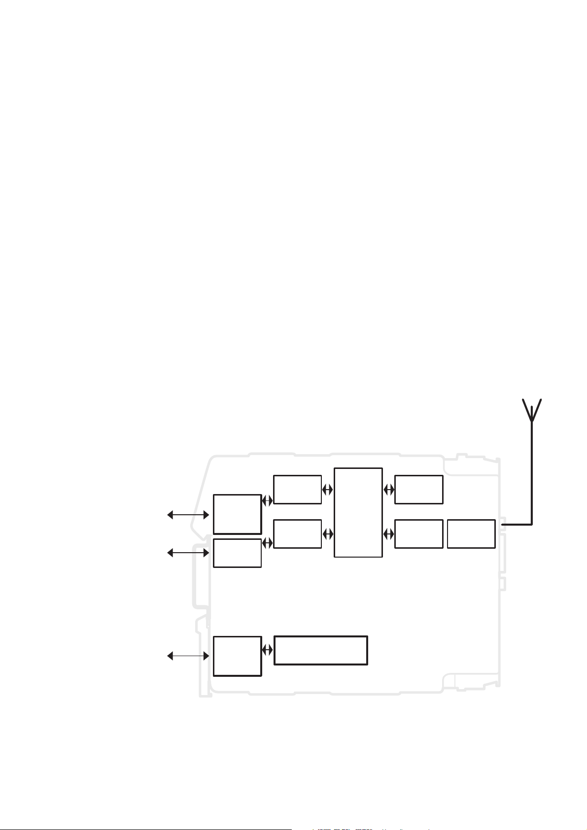
Wireless connection
to GSM network
SMA
connector
RF
Interface
SIM
card
RS-232
driver
Isolated
power supply
LED:s
GSM
Engine
Serial data
12–36 V DC
9-pos
D-sub
2-pos
screw
connector
5-pos
screw
connector
GD-01:
Page 4

4 6196-2211
Safety
General:
Before using this unit, read the manual completely, and make sure that you
understand it fully. Check that your application does not exceed the safe
operating specifications for this unit.
Before installation, maintenance or modification work:
Prevent damage to internal electronics from electrostatic discharges (ESD)
by discharging your body to a grounding point (e.g. use of wrist strap).
Prevent access to hazardous voltages by disconnecting the unit from AC/DC
mains supply and all others electrical connections.
Installation:
This unit is constructed for professional system use. It should be located in a
restricted access area, such as locked cabinet which can only be accessed by
service personnel.
This unit is intended for permanent connection to the AC/DC power supply
and should only be installed by qualified personnel.
The AC/DC power supply wiring must be sufficiently fused, and if necessary
it must be possible to disconnect the unit manually from the voltage supply.
Ensure compliance to national installation regulations.
This unit is a class II equipment, and does not rely on protective earthing.
This unit uses convection cooling.To avoid obstructions to the airflow around
the unit, follow the spacing recommendations (see Installation).
Approvals
Conformity with the Directive 99/5/EEC (Radio Equipment & Telecommunications
Terminal Equipment) has been assessed by application of the standards
• EN60950 (user safety),
• EN 301 489-1 (Electromagnetic compatibility),
• EN 301 489-7 (Electromagnetic compatibility),
• EN 61000-6-2 (Electromagnetic compatibility, industrial immunity),
• EN 61000-6-3 (Electromagnetic compatibility, residential emission)
• EN 301 419-1 (Radio spectrum matters),
• EN 301 420 (Radio spectrum matters),
The GD-series of modems are fully compliant with ETSI GSM Phase 2+ standard.
!
!
!
Page 5

56196-2211
Declaration of conformity
Page 6

6 6196-2211
Specifications
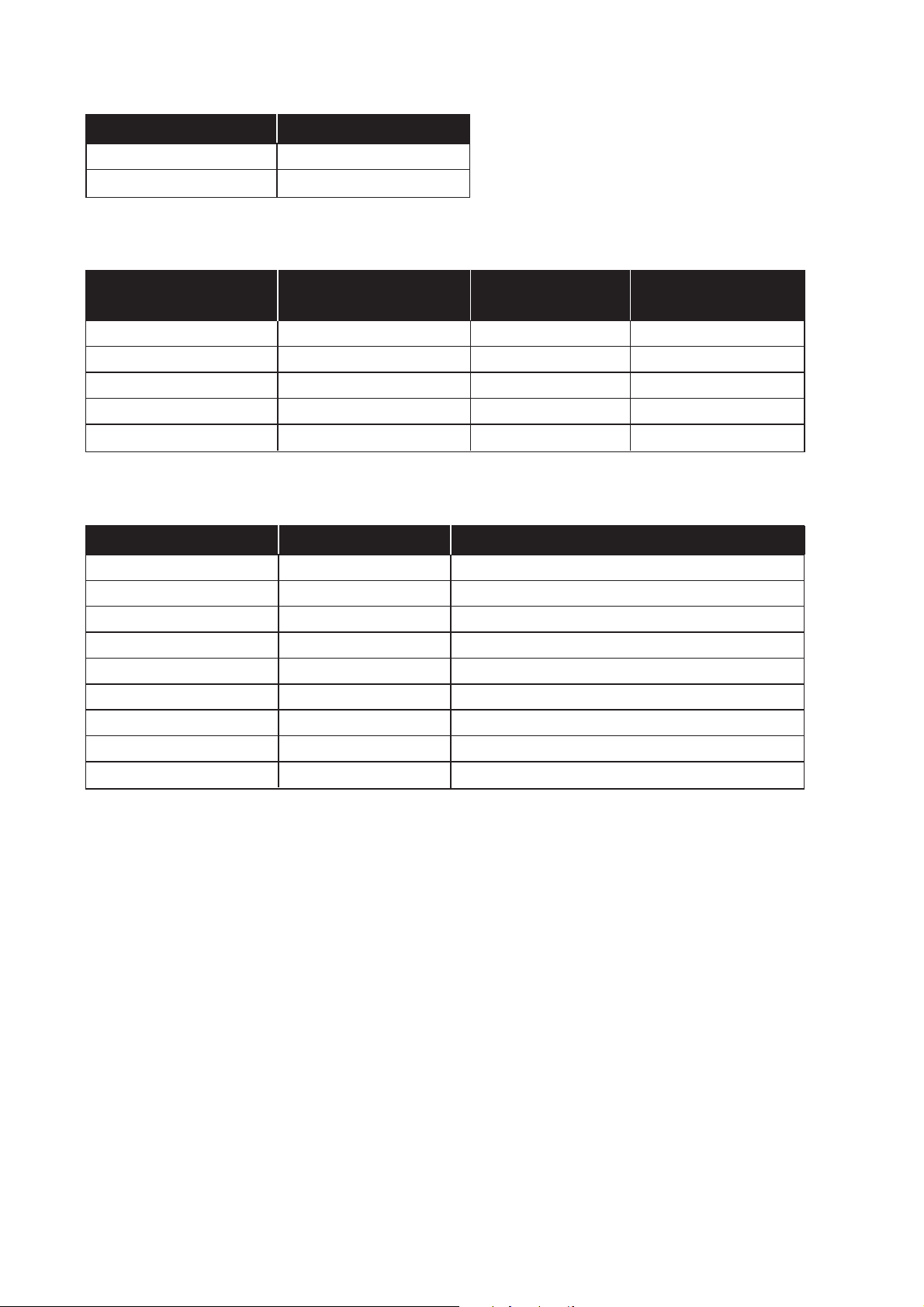
GSM services
Circuit Switched Data Asynchronous transparent or non-transparent
up to 14 400 bit/s
MNP2 error correction and V.42 bis data compression
Fax Fax group 3 (Class 1 and Class 2)
SMS 160 characters text or PDU
Point to point (MT/MO)
Cell broadcast
GPRS (optional) GPRS Class 2, Class B
Coding scheme: CS1 to CS4
Connections
Power interface
Rated voltage 12–36 V DC
Rated current @12 V DC: 200 mA / 40 mA
on line mode/ @24 V DC: 100 mA / 20 mA
idle mode @36 V DC: 67 mA / 17 mA
Connection Screw connector
Circuit type Power network
Special factors Reverse polarity protected
Communication and service interface, RS-232
Electrical specification RS-232
Data rate 300–115 200 bit/s
Data format 7 or 8 databits, Odd, Even, None, Mark or Space parity
Connection 9-pin D-sub and 5-pin screw connector
Circuit type SELV, max 15 m length, shielding not required
Communication interface, RS-422/RS-485 (only in GD-02)
Electrical specification RS-422/485
Data rate 300–115 200 bit/s
Data format 7 or 8 databits, Odd, Even or None parity
Connection 5-position screw block
Circuit type TNV-1, twisted pair, shielding not required
Special factors Bus turning time < 1.5 bit time
Page 7

76196-2211
Antenna interface
Frequency EGSM900: 880 – 915 and 925 – 960 MHz
GSM1800: 1 710 – 1 785 and 1 805 – 1 880 MHz
Connection 50 ohm impedance SMA male antenna connector
Special factors If not the supplied antenna is used, check the
“antenna information” section in this manual.
SIM interface 3 volts SIM cards supported
Insulation
Between circuits Electrical strength
Power to all other 1,5 kV RMS @ 50Hz
Alarm to all other
(only in GD-02) 0.5 kV RMS @ 50Hz
Climatic environment
Temperature,
operating 0 to 55°C
Temperature, storage
and transportation –25 to 70°C
Relative humidity,
operating 5 to 95% non-condensing
Relative humidity,
storage and transportation 5 to 95% condensation allowed outside packaging
Mechanics
Dimension, mm 55 x 100 x 128 (WxHxD)
Weight 0,3 kg
Mounting 35 mm DIN-rail
Degree of protection IP 20 (IEC 529)
Page 8

8 6196-2211
Maintenance
No maintenance is required, as long as the unit is used within the specified conditions.
Installation
Mounting /Removal
Before mounting or removing the unit:
Prevent damage to internal electronics from electrostatic discharges (ESD)
by discharging your body to a grounding point (e.g. use of wrist strap).
Prevent access to hazardous voltages by disconnecting the unit from AC/DC
mains supply and all others electrical connections.
Mounting
This unit should be mounted on 35 mm DIN rail which is horizontally mounted on a wall or cabinet backplate.
This unit use convention cooling. To avoid obstructions to the
airflow around the unit, use the following spacing rules.
Recommended spacing 25 mm (1.0 inch) above/below and 10
mm (0.4 inches) left/right the unit.
Snap on mounting (figure)
Removal
Press down the black support at the back of the unit
using a screwdriver (figure).
Min
10 mm
!
CLICK!
Page 9

96196-2211
Connections
GD-01
RS-232 interface,
5-position screw block
SIM interface
Antenna
interface
RS-232 interface,
9-pos D-sub
Power connection 12–36 V DC
Page 10
Connection Direction Description
9-pos D-sub no. 1 Out DCD
9-pos D-sub no. 2 Out RD
9-pos D-sub no. 3 In TD
9-pos D-sub no. 4 In DTR
9-pos D-sub no. 5 – Signal ground
9-pos D-sub no. 6 Out DSR
9-pos D-sub no. 7 In RTS
9-pos D-sub no. 8 Out CTS
9-pos D-sub no. 9 Out RI
Connection in GD-01 Connection in GD-02 Direction Description
5-pos screw connector 9-pos screw connector
15– Signal ground
2 6 Out CTS
3 7 In RTS
4 8 Out RD
59InTD
10 6196-2211
Power interface
Connection Description
2-pos screw block, + Power 12–36 V DC
2-pos screw block, – Power 12–30 V DC
RS-232 interface, screw connector
RS-232 interface, 9-pin D-sub
Page 11

116196-2211
Connection Direction Description
SMA male connector – 2W @ 900 MHz, 1W @ 1 800 MHz
Antenna interface
Connection Direction Description
SIM card – Supported SIM card voltage: 3 volt
SIM card interface
It is necessary to have a GSM subscription from a network operator.
They will provide you with a SIM card that should be mounted in the SIM card holder.
The SIM card holder is located under the top lid of the modem.
Press the button to eject the holder. Mount the SIM card in
the holder and make sure it is correctly installed before it is
pushed back into the modem.
Page 12

12 6196-2211
PWR LED on Correct internal power
LED off No internal power
NET LED off Device switched off - Not ready
LED on Device switched on Connecting to network
LED flashing slowly Device switched on Idle mode (registered on network)
LED flashing rapidly Device switched on Transmission mode
TD LED blinking LED showing data received from the local
RS-232/V24 port
LED off No data received on the local RS-232/V24 port
RD LED blinking LED showing data transmitted on the local
RS-232/V24 port
LED off No data transmitted on the local RS-232/V24 port
RTS LED on RS-232/V.24 RTS signal is active
LED off RS-232/V.24 RTS signal is inactive
CTS LED on RS-232/V.24 CTS signal is active
LED off RS-232/V.24 CTS signal is inactive
DCD LED on RS-232/V.24 DCD signal is active
LED off RS-232/V.24 DCD signal is inactive
LED indications
Page 13

136196-2211
Quick Start guide
The serial interface is default configured to:
• 9600 bit/s, 8 databits, no parity and 1 stop bit. (refer to AT+IPR and AT+ICF commands)
• RTS / CTS flowcontrol enabled (please refer to AT+IFC command)
• DTR signal must be active from the DTE (please refer to AT&Dn command)
Follow the steps below to get the unit up and running as quick as possible:
• Insert a valid SIM-card with correct services enabled (e.g. incoming and outgoing
DATA service)
• Make sure that the antenna is connected and placed in the best position possible.
• Power on the unit and make sure that the PIN code of the SIM-card is disabled either
with the help of a mobile phone or with the command AT+CLCK. If the PIN code
should be enabled make sure to enter the correct PIN code with the command
AT+CPIN.
• Check on the front of the GD that the NET LED is flashing , this means that the unit
has a connection to the GSM network and that it is registered.
• Check with a terminal program the received signal quality (please refer to AT+CSQ
command) The value of the first parameter reported from the +CSQ command
should be between 10 and 31, the value of the second parameter should always be 0.
• Make sure that the DTE equipment is connected and configured with the same serial
settings as the GD unit.
• Configure the GD unit with appropriate commands as needed in the specific application. Please refer to the application examples in the end of the full manual on the CD.
Page 14

14 6196-2211
Command Description Direct +CSAS &W &F Default
Save value
+CGMI Manufacturer identification – – – – –
+CGMM Request model identification – – – – –
+CGMR Request revision identification – – – – –
+CGSN Product Serial Number – – – – –
+CSCS Select TE character set – – x x “PPCP437”
+WPCS Phonebook Character Set – – x x “TRANSPARENT”
+CIMI Request IMSI – – – – –
+CCID Card Identification – – – – –
+GCAP Capabilities list – – – – –
+CPOF Power off – – – – –
+CFUN Set phone functionality – – – – –
+CPAS Phone activity status – – – – –
+CMEE Report Mobile Equipment errors – – x x 0
+CKPD Keypad control – – – – –
+CCLK Clock Management – – – – –
+CALA Alarm Management – – – – –
Short form list of AT commands
S-registers Description Direct +CSAS &W &F Default
Save value
S0 Ring signals before auto answer - - x x 0
General commands
Configuration
The GD-01 can be configured via AT-commands on the service interface.
Page 15

156196-2211
Command Description Direct +CSAS &W &F Default
Save value
+CSQ Signal Quality – – – – –
+COPS Operator selection x – x x 0,2
+CREG Network registration – – x x 0
+WOPN Read operator name – – – – –
+CPOL Preferred operator list – – – – –
Network service commands
Command Description Direct +CSAS &W &F Default
Save value
+CPIN Enter PIN – – – – –
+CPIN2 Enter PIN2 – – – – –
+CPINC PIN remaining attempt number – – – – –
+CLCK Facility lock – – – – –
+CPWD Change password – – – – –
Security commands
Command Description Direct +CSAS &W &F Default
Save value
D Dial command - – – – –
H Hang–Up command – – – – –
A Answer a call – – – – –
+CEER Extended error report – – – – –
+VTD DTMF signals tone duration – – – – –
+VTS Send DTMF signals – – – – –
%Dn Automatic dialing with DTR – – x x 0
+CICB Incoming Call Bearer – – x x 2
+CSNS Single Numbering Scheme – – x x 0
Call control commands
Command Description Direct +CSAS &W &F Default
Save value
+CPBS Select phonebook memory storage - - - - +CPBR Read phonebook entries - - - - +CPBF Find phonebook entries - - - - +CPBW Write phonebook entry - - - - +CPBP Phonebook phone search - - - - +CPBN Move action in phonebook - - - - +CNUM Subscriber number - - - - +WAIP Avoid phonebook init - - x x 0
+WDCP Delete Calls Phonebook - - - - +CSVM Set Voice Mail Number x - - x 0
Phonebook commands
Page 16

16 6196-2211
Command Description Direct +CSAS &W &F Default
Save value
+CSMS Select message service x – – – 0
+CNMA New Message Acknowledgement – – – – –
+CPMS Preferred Message Storage – – – – –
+CMGF Preferred Message Format – – x x 1
+CSAS Save Settings – – – – –
+CRES Restore settings – – – – –
+CSDH Show text mode parameters – – x x 0
+CNMI New message indication – x – x 0,1,0,0,0
+CMGR Read message – – – – –
+CMGL List message – – – – –
+CMGS Send message – – – – –
+CMGW Write Message to Memory – – – – –
+CMSS Send Message From Storage +CMSS – – – – –
+CSMP Set Text Mode Parameters – x – x 1,167,0,0
+CMGD Delete message – – – – –
+CSCA Service center address – x – – SIM dependant
+CSCB Select Cell Broadcast Message Types – – – – –
+WCBM Cell Broadcast Message Identifiers – – – – –
+WMSC Message status modification – – – – –
+WMGO Message overwriting – – – – –
+WUSS Unchange SMS Status – x – x 0
Short Messages commands
Command Description Direct +CSAS &W &F Default
Save value
+CCFC Call forwarding – – – – –
+CLCK Call barring – – – – –
+CPWD Modify SS password – – – – –
+CCWA Call waiting – – x x 0
+CLIR Calling line identification restriction – – – – –
+CLIP Calling line identification presentation – – x x 0
+COLP Connected line identification presentation – – x x 0
+CAOC Advice of charge – – – – –
+CACM Accumulated call meter – – – – –
+CAMM Accumulated call meter maximum – – – – –
+CPUC Price per unit and currency table – – – – –
+CHLD Call related supplementary services – – – – –
+CLCC List current calls – – – – –
+CSSN Supplementary service notifications – – x x 0,0
+CUSD Unstructured supplementary service data x – – x 0
+CCUG Closed user group x – – – 0,0,0
Supplementary Services commands
Page 17

176196-2211
Command Description Direct +CSAS &W &F Default
Save value
+CBST Bearer type selection – – x x 0,0,1
+FCLASS Select mode – – – – –
+CR Service reporting control – – x x 0
+CRC Cellular result codes – – x x 0
+ILRR DTE–DCE local rate reporting – – x x 0
+CRLP Radio link protocol parameters – – x x 61,61,48,6,1
+DOPT Others radio link parameters – – x x 1,1
%C Select data compression – – x x 2
+DS V42 bis data compression – – x x 3,0,4096,20
+DR V42 bis data compression report – – x x 0
\N Select data error correcting mode – – x x 0
Data commands
Command Description Direct +CSAS &W &F Default
Save value
+FTM Transmit speed – – – – –
+FRM Receive speed – – – – –
+FTH HDLC transmit speed – – – – –
+FRH HDLC receive speed – – – – –
+FTS Stop transmission and wait – – – – –
+FRS Receive silence – – – – –
Fax class 1 commands
Command Description Direct +CSAS &W &F Default
Save value
+FDT Transmit Data – – – – –
+FDR Receive Data – – – – –
+FET Transmit page punctuation – – – – –
+FPTS Page transfer status parameters – – – – –
+FK Terminate Session – – – – –
+FBOR Page transfer bit order – – x x 0
+FBUF Buffer size report – – – – –
+FCQ Copy quality checking – – x x 0
+FCR Capability to receive – – x x 1
+FDIS Current sessions parameters – – x x 0,5,0,0,2,0,0,0,0
+FDCC DCE capabilities parameters – – x x 0,5,0,0,2,0,0,0,0
+FLID Local ID string – – – – –
+FPHCTO Page transfer timeout parameter – – x x 30
Fax class 2 commands
Page 18

18 6196-2211
Command Description Direct +CSAS &W &F Default
Save value
+IPR Fixed DTE rate – – x – 9600
+ICF DTE–DCE character framing – – x – 3,4
+IFC DTE–DCE local flow control – – x – 2,2
&C Set DCD signal – – x – 1
&D Set DTR signal – – x – 1
&S Set DSR signal – – x – 1
O Back to online mode – – – – –
Q Result code suppression – – x x 0
V DCE response format – – x x 1
Z Default configuration – – – – –
&W Save configuration – – – – –
&T Auto–tests – – – – –
E Echo – – x – 1
&F Restore factory settings – – – – –
&V Display configuration – – – – –
I Request identification information – – – – –
+WMUX Data / Commands Multiplexing – – x x 0
V24-V25 commands
Command Description Direct +CSAS &W &F Default
Save value
+CCED Cell environment description – – – – –
+CCED Automatic RxLev indication – – – – –
+WIND General Indications x – – x 0
+CMER Mobile Equipment event reporting – – x x 0
+WLPR Read Language Preference – – – – –
+WLPW Write Language Preference – – – – –
+WAC Abort command – – – – –
+WDWL Downloading – – – – –
+WDR Data Rate x – – – 2
+WHWV Hardware Version – – – – –
+WDOP Date of Production – – – – –
+WSTR Status Request – – – – –
+WSCAN Scan – – – – –
+WRIM Ring Indicator Mode – – – – –
+W32K 32kHz Power down Mode – – – – –
+WSSW Internal Software version – – – – –
+WCCS Custom Character Set – – – – –
+WLCK Lock – – – – –
+CPHS CPHS command x – – x 0
+WMIR Customer storage mirror – – – – –
+WMBN CPHS Mail Box Number – – – – –
+WRST Reset – – – – –
+WLOC Local Information – – – – –
+WATH Hang–up – – – – –
Specific AT commands
Page 19

196196-2211
Command Description Direct +CSAS &W &F Default
Save value
+CGDCONT Define PDP Context – – – – –
+CGQREQ Requested Quality of Service Profile – – – – –
+CGQMIN (Minimum acceptable)
Quality of Service Profile – – – – –
+CGATT GPRS attach or detach – – – – –
+CGACT PDP context activate or deactivate – – – – –
+CGDATA Enter data state – – – – –
+CGCLASS GPRS mobile station class – – – – –
+CGSMS Select service for MO SMS messages – – – – –
+CGEREP GPRS event reporting – – – – –
+CGREG GPRS network registration status – – – – –
D Request GPRS IP service – – – – –
+CGAUTO Automatic response to a network
request for PDP context activation – – – – –
+CGANS Manual response to a network
request for PDP context activation – – – – –
+CGPADDR Show PDP address – – – – –
+CGCOUNTERS PDP Counters Infos – – – – –
+WGPRS GPRS PARAMETERS CUSTOM: – – – – –
+WGAUTH Set authentication parameters – – – – –
+WGIPCPINF Get IPCP informations – – – – –
AT commands for GPRS
Page 20

6196-2211 02.10 Eskilstuna Offset AB, Eskilstuna, Sweden
Westermo Teleindustri AB • SE-640 40 Stora Sundby, Sweden
Phone +46 16 42 80 00 Fax +46 16 42 80 01
E-mail: info@westermo.se • Westermo Web site: www.westermo.se
Westermo Teleindustri AB have distributors in several
countries, contact us for further information.
Westermo Data Communications Ltd
Unit 14 Talisman Business Centre • Duncan Road
Park Gate, Southampton • SO31 7GA
Phone: +44(0)1489 580 585 • Fax.:+44(0)1489 580586
E-Mail: sales@westermo.co.uk • Web: www.westermo.co.uk
Westermo Data Communications GmbH
Goethestraße 67, 68753 Waghäusel
Tel.: +49(0)7254-95400-0 • Fax.:+49(0)7254-95400-9
E-Mail: info@westermo.de • Web: www.westermo.de
Westermo Data Communications S.A.R.L.
9 Chemin de Chilly 91160 CHAMPLAN
Tél : +33 1 69 10 21 00 • Fax : +33 1 69 10 21 01
E-mail : infos@westermo.fr • Site WEB: www.westermo.fr
Subsidiaries
Application examples
ISDN
GD-01
ID-90PC PC
PSTN
TD-33 PC
GD-01PC
GD-01 PC
GD-01
PLC
123456789123456789
R+ R- T+T- T+ T- R+ R-
CHANNEL 3
PWR
RD
TD
DCD2
DCD3
DCD4
CHANNEL 2 POWER
R+ R- T+ T12345
123456789123456789
R+ R- T+T- T+ T- R+ R-
CHANNEL 3
PWR
RD
TD
DCD2
DCD3
DCD4
CHANNEL 2 POWER
R+ R- T+ T12345
123456789123456789
R+ R- T+T- T+ T- R+ R-
CHANNEL 3
PWR
RD
TD
DCD2
DCD3
DCD4
CHANNEL 2 POWER
R+ R- T+ T12345
123456789123456789
R+ R- T+T- T+ T- R+ R-
CHANNEL 3
PWR
RD
TD
DCD2
DCD3
DCD4
12-36V DC
- +
12-36V DC
- +
123456789123456789
R+ R- T+T- T+ T- R+ R-
CHANNEL 3
PWR
RD
TD
DCD2
DCD3
DCD4
12-36V DC
- +
CHANNEL 2 POWER
R+ R- T+ T12345
12-36V DC
- +
CHANNEL 2 POWER
R+ R- T+ T12345
123456789123456789
R+ R- T+T- T+ T- R+ R-
CHANNEL 3
PWR
RD
TD
DCD2
DCD3
DCD4
CHANNEL 2 POWER
R+ R- T+ T12345
12-36V DC
- +
12-36V DC
- +
 Loading...