

Page 1
User Guide
6660-2201
WeOS
FDV-206-1D1S
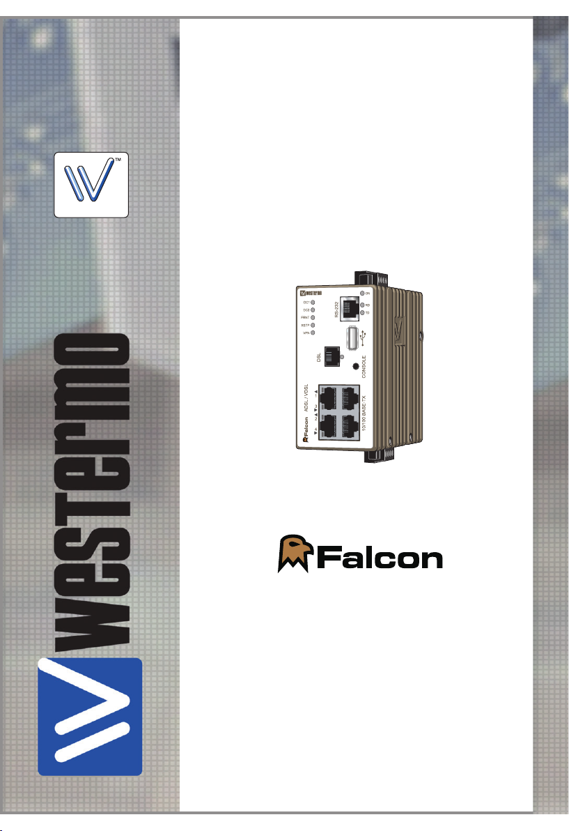
FALCON SERIES
Westermo Teleindustri AB
©
The Industrial Broadband Router
www.westermo.com
Page 2

Software tools
Related software tools are available in the folder software tools under technical support on the Westermo website.
License Information
This device contains public available software which is under the GPL license.
For more information see legal.pdf included with all firmware releases.
This product includes software developed by the OpenSSL Project for use in the
OpenSSL Toolkit. http://www.openssl.org
Legal information
The contents of this document are provided “as is”. Except as required by applicable
law, no warranties of any kind, either express or implied, including, but not limited to,
the implied warranties of merchantability and fitness for a particular purpose, are made
in relation to the accuracy and reliability or contents of this document. Westermo
reserves the right to revise this document or withdraw it at any time without prior
notice.
Under no circumstances shall Westermo be responsible for any loss of data or income
or any special, incidental, and consequential or indirect damages howsoever caused.
More information about Westermo can be found at the following Internet address:
http://www.westermo.com
2
6660-2201
Page 3

Safety
!
!
Before installation:
Read this manual completely and gather all information on the unit. Make sure that
you understand it fully. Check that your application does not exceed the safe operating specifications for this unit.
This unit should only be installed by qualified personnel.
This unit should be built-in to an apparatus cabinet, or similar, where access is
restricted to service personnel only.
The power supply wiring must be sufficiently fused, and if necessary it must be
possible to disconnect manually from the power supply. Ensure compliance to
national installation regulations.
This unit uses convection cooling. To avoid obstructing the airflow around the unit,
follow the spacing recommendations (see Cooling section).
Before mounting, using or removing this unit:
Prevent access to hazardous voltage by disconnecting the unit from power supply.
Warning! Do not open connected unit. Hazardous voltage may occur within this
unit when connected to power supply.
Care recommendations
Follow the care recommendations below to maintain full operation of unit and to fulfil
the warranty obligations.
This unit must not be operating with removed covers or lids.
Do not attempt to disassemble the unit. There are no user serviceable parts inside.
Do not drop, knock or shake the unit, rough handling above the specification may cause
damage to internal circuit boards.
Do not use harsh chemicals, cleaning solvents or strong detergents to clean the unit.
Do not paint the unit. Paint can clog the unit and prevent proper operation.
Do not expose the unit to any kind of liquids (rain, beverages, etc). The unit is not water-
proof. Keep the unit within the specified humidity levels.
Do not use or store the unit in dusty, dirty areas, connectors as well as other mechanical
part may be damaged.
If the unit is not working properly, contact the place of purchase, nearest Westermo dis-
tributor office or Westermo Tech support.
Fibre connectors are supplied with plugs to avoid contamination inside the optical port.
As long as no optical fibre is mounted on the connector, e.g. for storage, service or
transportation, should the plug be applied.
Maintenance
No maintenance is required, as long as the unit is used as intended within the specified
conditions.
6660-2201
3
Page 4
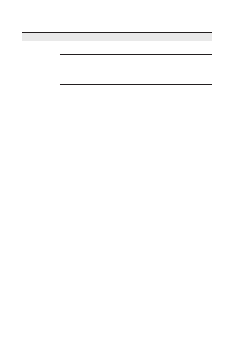
Agency approvals and standards compliance
Type Approval / Compliance
EMC EN 55024, EN 55024 A1, EN 55024 A2,
Safety EN 60950-1, IT equipment
Electromagnetic compatibility – Immunity IT equipment
EN 55022, EN 55022 A1, Information technology equipment.
Radio disturbance characteristics. Limits and methods of measurement
EN 61000-6-2, Immunity industrial environments
EN 61000-6-4, Emission industrial environments
EN 61000-6-3, Emission residential, commercial and light-industrial
environments
FCC part 15 Class A and Class B
EN 50121-4, Railway signalling and telecommunications apparatus
FCC Part 15.105 Notice:
This equipment has been tested and found to comply with the limits for a
Class B digital device, pursuant to Part 15 of the FCC Rules. These limits
are designed to provide reasonable protection against harmful interference
in a residential installation. This equipment generates, uses and can radiate
radio frequency energy and, if not installed and used in accordance with
the instructions, may cause harmful interference to radio communications.
However, there is no guarantee that interference will not occur in a particular installation. If this equipment does cause harmful interference to radio
or television reception, which can be determined by turning the equipment
off and on, the user is encouraged to try to correct the interference by
one or more of the following measures:
… Reorient or relocate the receiving antenna
… Increase the separation between the equipment and receiver
… Connect the equipment into an outlet on a circuit different from that to
which the receiver is connected
… Consult the dealer or an experienced radio/TV technician for help.
4
6660-2201
Page 5

Declaration of Conformity
Org.nr/
Westermo Teleindustri AB
Declaration of conformity
The manufacturer
Herewith declares that the product(s)
Type of product Model Art no
Industrial ADSL/VDSL router FALCON FDV-206-1D1S 3660-0100
is in conformity with the following EC directive(s).
No Short name
2004/108/EC Electromagnetic Compatibility (EMC)
1999/5/EC Radio equipment and Telecommunications terminal equipment (R&TTE)
References of standards applied for this EC declaration of conformity.
No Title Issue
EN 50121-4 Railway applications – Electromagnetic compatibility – Emission
EN 55022 Information technology equipment - Emission 2006
EN 55024 Information technology equipment - Immunity 1998
EN 61000-6-1 Electromagnetic compatibility – Immunity for residential
EN 61000-6-2 Electromagnetic compatibility – Immunity for industrial
EN 61000-6-4 Electromagnetic compatibility – Emission for industrial
EN 60950-1 Information technology equipment - Safety 2006
The last two digits of the year in which the CE marking was affixed: 10
Westermo Teleindustri AB
SE-640 40 Stora Sundby, Sweden
and immunity of the signalling and telecommunications apparatus
environments
environments
environments
2006
+A1:2007
+A1:2001
+A2:2003
2007
2005
2007
+A11:2009
Pierre Öberg
Technical Manager
1st September 2010
Postadress/Postal address
S-640 40 Stora Sundby 016-428000 016-428001 52 72 79-4 5671-5550 556361-2604 Eskilstuna
Sweden Int+46 16428000 Int+46 16428001
Tel.
Telefax
Postgiro
Bankgiro Corp. identity number Registered office
6660-2201
5
Page 6

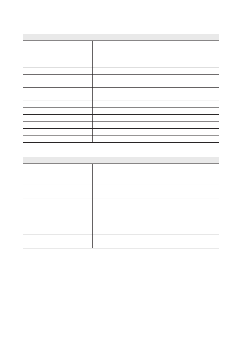
Type tests and environmental conditions
Phenomena Test Description Test levels
ESD EN 61000-4-2 Enclosure contact ± 6 kV
RF field AM modulated EN 61000-4-3 Enclosure 20 V/m 80% AM (1 kHz), 80 – 2 700 MHz
Fast transient EN 61000-4-4 Signal ports ± 2 kV
Surge EN 61000-4-5 Signal ports unbalanced ± 2 kV line to earth, ± 2 kV line to line
RF conducted EN 61000-4-6 Signal ports 10 V 80% AM (1 kHz), 0.15 – 80 MHz
Pulse magnetic field EN 61000-4-9 Enclosure 300 A/m, 6.4 / 16 µs pulse
Voltage dips and
interruption
Radiated emission EN 55022 Enclosure Class A
Conducted emission EN 55022 AC power ports Class B
Dielectric strength EN 60950 Signal port to other
Temperature Operating –20 to +70ºC
Humidity Operating 5 to 95% relative humidity
Altitude Operating 2000 m / 70 kPa
Reliability prediction
(MTBF)
Service life Operating 10 year
Vibration IEC 60068-2-6 Operating 5 – 20 Hz: 2 m²/s³
Shock IEC 60068-2-27 Operating 6 ms 1000 m/s²
Enclosure UL 94 PC / ABS Flammability class V-1
Dimension W x H x D 52.5 x 100 x 101 mm
Weight 0.6 kg
Degree of protection IEC 529 Enclosure IP 40
Cooling Convection
Mounting Horizontal on 35 mm DIN-rail
EN 61000-4-29 DC power ports 10 & 100 ms, interruption
FCC part 15 Class A
FCC part 15 AC power ports Class B
EN 55022 DC power ports Class B
MIL-HDBK- 217F Operating 580 000 hours @ 25°C
Enclosure air ± 8 kV
Power ports ± 2 kV
Signal ports balanced ± 2 kV line to earth, ± 1 kV line to line
Power ports ± 2 kV line to earth, ± 2 kV line to line
Power ports 10 V 80% AM (1 kHz), 0.15 – 80 MHz
10 ms, 30% reduction
10 ms, 60% reduction
+20% above & –20% below rated voltage
isolated ports
Power port to other
isolated ports
Storage & Transport –40 to +85ºC
Storage & Transport 5 to 95% relative humidity
1.5 kVrms 50 Hz 1 min
3 kVrms 50 Hz 1 min
2 kVrms 50 Hz 1 min (@ rated power <60 V)
20 – 200 Hz: – 3 dB/oct
3 axis = 3 * 30 min
6 directions, 3 shocks / direction
6
6660-2201
Page 7

Description
Falcon, The Industrial Broadband Router. Falcon is the first purpose built
INDUSTRIAL VDSL2 router and delivers secure, high-speed access to vital remote assets.
Many broadband circuits are still using ADSL and the Falcon has therefore been designed
to operate on ADSL / ADSL2 / ADSL2+ lines as well.
Incredibly compact and built into a purpose designed case with an integrated DIN rail
clip, the Falcon has an operational temperature between –20 to +70ºC and is designed
to operate in industrial EMC levels. High MTBF figures lead to an expected service life
of more than 10 years.
The Falcon comes equipped with a built in 4 port layer 3 routing switch and can cope
with older legacy devices running RS-232 with its built in device server interface, making
it perfect for analogue modem replacement projects.
The Westermo Operating System (WeOS) is a feature rich operating system designed
for the industrial markets. It provides the Falcon with cyber security functionality, such
as DMZ, IPsec VPNs and a stateful inspection firewall configured to be secure by default.
6660-2201
7
Page 8
Interface specifications
Power
Rated voltage 24 to 48 VDC
Operating voltage 19 to 60 VDC
Rated current 460 mA @ 24 VDC
Rated frequency DC
Inrush current, I2t 1 mA²s @ 24 VDC
Startup current* 760 mApeak @ 24 VDC
Polarity Reverse polarity protected
Redundant power input Yes
Isolation to All other
Connection Detachable screw terminal
Connector size 0.2 – 2.5 mm² (AWG 24 – 12)
Shielded cable Not required
* With fully loaded USB port. External supply current capability for proper startup
RS-232
Electrical specification EIA RS-232
Data rate 300 bit/s – 115.2 kbit/s
Data format 7 or 8 data bits, Odd, even or none parity, 1 or 2 stop bits
Protocol Transparent, optimised by packing algorithm
Circuit type SELV
Transmission range 15 m / 49 ft
Isolation to Power, DSL, Ethernet
Galvanic connection to USB, Console
Connection RJ-45*
Shielded cable Not required
Conductive housing Ye s
Number of ports 1
* RJ-45 to RS-232 converter cable included.
220 mA @ 48 VDC
3 mA²s @ 48 VDC
500 mApeak @ 48 VDC
8
6660-2201
Page 9

Ethernet TX
Electrical specification IEEE std 802.3. 2005 Edition
Data rate 10 Mbit/s, 100 Mbit/s, manual or auto
Duplex Full or half, manual or auto
Transmission range 150 m, according to long cable specification
Isolation to All other
Connection RJ-45 auto MDI/MDIX
Shielded cable Not required, except when installed in Railway applications as
signalling and telecommunications apparatus and located close
to rails.*
Conductive housing Ye s
Number of ports 4
* To minimise the risk of interference, a shielded cable is recommended when the cable is located inside 3 m
boundary to the rails and connected to this port.
The cable shield should be properly connected (360º) to an earthing point within 1 m from this port.
This earthing point should have a low impedance connection to the conductive enclosure of the apparatus
cabinet, or similar, where the unit is built-in. This conductive enclosure should be connected to the earthing
system of an installation and may be directly connected to the protective earth.
Console
Electrical specification TTL-level
Data rate 115.2 kbit/s
Data format 8 data bits, none parity, 1 stop bit, no flow control
Circuit type SELV
Transmission range 15 m
Isolation to Power, DSL, Ethernet
Galvanic connection to Serial, USB
Connection 2.5 mm jack, use Westermo cable 1211-2027
6660-2201
9
Page 10

USB
Electrical specification USB 2.0 host interface
Data rate Up to 12 Mbit/s (full-speed mode)
Circuit type SELV
Maximum supply current 500 mA
Isolation to Power, DSL, Ethernet
Galvanic connection to Serial, Console
Connection USB receptacle connector type A
I/O / Relay output
Connect resistance 30 Ω
Isolation to All other
Connection Detachable screw terminal
Connector size 0.2 – 2.5 mm² (AWG 24 -12)
Maximum voltage/current 60 VDC / 80 mA
I/O / Digital input
Voltage levels Logic one >12V, Logic zero <1V
Isolation to All other
Connection Detachable screw terminal
Connector size 0.2 – 2.5 mm² (AWG 24 -12)
DSL
Electrical specification See standard table below
Data rate 250 Mbit U/D, limited to 100 Mbit
Protocol EFM (VDSL2), LLC/VC-MUX encap Ethernet (ADSL), PPPoE
(ADSL / VDSL2)
Isolation to All other
Connection RJ-11
Shielded cable Not required, except when installed in Railway applications as
signalling and telecommunications apparatus and located close
to rails.*
Number of ports 1
Standard Annex
ETSI TS 101 270 N/A
ITU-T 993.2 (VDSL2) A , B, J
T1.424 N/A
ITU-T G.992.1 (ADSL) A, B (non overlap)
ITU-T G.992.2 (ADSL lite) A (non overlap)
ITU-T G.992.3 (ADSL2) A, B, I, J, L, M (non overlap)
ITU-T G.992.5 (ADSL2+) A, B, I, J, M (non overlap)
ANSI T1.413 N/A
* To minimise the risk of interference, a shielded cable is recommended when the cable is located inside 3 m
boundary or the cable is longer than 30 m and inside 10 m boundary to the rails and connected to this port.
10
6660-2201
Page 11

Location of interface ports and LED’s
LED Indicators (for details see page 14)
Power Connection (for details see page 8 and 12)
RS-232
Position Direction* Description
No. 1 Out DSR (Data Set ready)
No. 2 Out DCD (Data Carrier Detect)
No. 3 In DTR (Data Terminal ready)
No. 4 In/Out SG (Signal Ground)
No. 5 Out RD (Receive Data)
No. 6 In TD (Transmit Data)
No. 7 Out CTS (Clear To Send)
No. 8 In RTS (Request To Send)
USB
Position Direction* Description
No. 1 Out VBUS
No. 2 In/Out D–
No. 3 In/Out D+
No. 4 Out GND
Shield In/Out Connected to protective earth
DSL
Position Direction* Description
No. 1 –
No. 2 In/Out 2-wire Receive/Transmit DSL
No. 3 In/Out 2-wire Receive/Transmit DSL
No. 4 –
* Direction relative this unit.
6660-2201
Console
(for details see page 9 and 13)
Ethernet TX
Position Direction* Description
No. 1 In/Out TD+
No. 2 In/Out TD–
No. 3 In/Out RD+
No. 4 – Not connected
No. 5 –
No. 6 In/Out RD–
No. 7 – Not connected
No. 8 – Not conneced
11
Page 12

Power connection
4-position Product marking Direction Description
1
2
3
4
No. 1 +DC1 Input Supply voltage input DC1
No. 2 +DC2 Input Supply voltage input DC2
No. 3 -COM Input Common
No. 4 -COM Input Common
Falcon supports redundant power connection. The positive inputs are +DC1 and +DC2, the negative input for
both supplies are –COM. Connect the primary voltage (e.g. +24 VDC) to the +DC1 pin and return to one of the
–COM pins on the power input.
I/O connection
4-position Product marking Direction Description
1
2
3
4
The Status output is a potential free, opto-isolated normally closed solid-state relay.
This can be configured to monitor various alarm events within the Falcon unit, see WeOS Management Guide.
An external load in series with an external voltage source is required for proper functionality.
For voltage/current ratings, see Interface Specification section.
No. 1 Status + Output Alarm relay (status) contact
No. 2 Status – Output Alarm relay (status) contact
No. 3 Digital in + Input Digital in +
No. 4 Digital in – Input Digital in –
The Digital in is an opto-isolated
digital input which can be used to
monitor external events. For voltage/current ratings, see Interface
Specification section:
12
Falcon
External
Load
1
Status
2
3
4
V
+
V
–
Digital In
6660-2201
Page 13

Cable 1211-2027
Connection to console port
The console port can be used to connect to the CLI
(Command Line Interface).
The following steps needs to be taken
1. Connect the serial diagnostic cable to the console port
(use only Westermo cable 1211-2027).
2. Connect cable to your computer (USB port, if drivers are needed they can be downloaded
from our Web page).
3. Use a terminal emulator and connect with correct speed and format (115200, 8N1)
to the assigned port.
For more information about the CLI, see the WeOS management guide.
6660-2201
13
Page 14

LED indicators
LED Status Description
ON OFF Unit has no power
DC1 OFF Unit has no power
DC2 OFF Unit has no power
VPN OFF VPN disabled.
RSTP OFF RSTP disabled.
FRNT OFF FRNT disabled.
DSL OFF No xDSL link
RD OFF No serial data transmitted
TD OFF No serial data received
Copper ports
Port 1-4
GREEN All OK, no alarm condition.
RED Alarm condition, or until unit has started
FLASH Location indicator ("Here I am!"). Activated
GREEN Power OK on DC1.
RED Power failure on DC1.
GREEN Power OK on DC2.
RED Power failure on DC2.
GREEN (Configurable) Default: At least one VPN
RED (Configurable) Default: All VPN tunnels
GREEN RSTP enabled.
BLINK Unit elected as RSTP/STP root switch.
GREEN FRNT OK.
RED FRNT Error.
BLINK Unit configured as FRNT focal point.
GREEN xDSL link established
GREEN
BLINK
GREEN
FLASH
GREEN
FLASH
OFF No link
GREEN Link established
GREEN
FLASH
YELLOW Port alarm and no link. Or if FRNT or RSTP
up. (Alarm conditions are configurable, see
''WeOS Management Guide'')
when connected to IPConfig Tool, or upon
request from Web or CLI.
tunnel up and OK
down.
xDSL link negotiation
Serial data transmitted
Serial data received
Data traffic indication
mode, port is blocked.
14
6660-2201
Page 15

Mounting
This unit should be mounted on 35 mm DIN-rail, which is horizontally mounted inside an
apparatus cabinet or similar. It is recommended that the DIN-rail is connected to ground.
Snap on mounting, see figure.
Mounting Falcon with integrated DIN-clip:
Removal
Removing Falcon with integrated DIN-clip:
Press down the support at the back of the unit using a screwdriver. See figure.
Cooling
This unit uses convection cooling.
To avoid obstructing the airflow
around the unit, use the following
spacing rules. Minimum spacing 25 mm
(1.0 inch) above / below and 10 mm
(0.4 inches) left / right the unit.
Spacing is recommended for the use
of unit in full operating temperature
range and service life.
6660-2201
10mm 10mm
15
Page 16

Factory default
It is possible to set the unit to factory default settings by using two standard Ethernet RJ-45 cables.
1. Power off the switch and disconnect all Ethernet cables (copper and fibre).
2. Connect one Ethernet cable between Ethernet ports 1 and 4, and the other between Ethernet
ports 2 and 3.
The ports need to be connected directly by an Ethernet cable, i.e., not via a hub or switch. Use a
straight cable – not a cross-over cable – when connecting the ports.
3. Power on the unit.
4. Wait for the unit to start up. Control that the ON LED is flashing red.
The ON LED flashing indicates that the unit is now ready to be reset to factory default. You now
have the choice to go ahead with the factory reset, or to skip factory reset and boot as normal.
• Go ahead with factory reset:
Acknowledge that you wish to conduct the factory reset by unplugging the
Ethernet cables. The ON LED will stop flashing.
This initiates the factory reset process*, and after approximately 1 minute the unit will restart
with factory default settings. When the switch has booted up, the ON LED will show a green
light, and is now ready to use.
• Skip the factory reset:
To skip the factory reset process, just wait for approximately 30 seconds
(after the ON LED starts flashing RED) without unplugging the Ethernet cables.
The switch will conduct a normal boot with the existing settings.
* Note Do not power off the unit while the factory reset process is in progress.
Default Network Settings
IP address (Ethernet ports) 192.168.2.200
Netmask (Ethernet ports) 255.255.255.0
Gateway Acquired from the provider via DHCP
Username admin
Password westermo
Default DSL Settings
DSL Connection type ADSL/ADSL2/ADSL2+ on Annex A
VPI / VCI 8 / 35
Authentication Routed / DHCP acquired IP
Getting Started
Westermo Operating System (WeOS) provides several different ways to configure a unit:
Web Configuration of the unit using the Made Easy Web Interface.
Command Line
Interface (CLI)
IPConfig tool Discover your Westermo devices and configure basic settings, mainly the IP address. Use this
The recommended and most easy to use selection is the web-based management tool.
16
Configuration of the unit via the Command Line Interface. Provides the most advanced
settings and diagnostics tools. Accessible via SSH or the console cable, Westermo article
number 1211-2027.
tool if you cannot connect to the unit with it's current IP address.
For more information about the IP Config Tool and how to use it, see chapter 4 in the
Management Guide.
Note! IP Config Tool version must be 10.4.0 or higher.
6660-2201
Page 17

Step-by-step guide to configure a DSL-connection
using the web interface
Power Connection
ADSL/VDSL2
connection (RJ-11)
PC/Ethernet
connection (RJ-45)
Step 1 – Power-up the unit and wait for it to become ready
Connect the Falcon to the DSL-network using the RJ-11, connect an RJ-45 cable from
one of the four Ethernet-ports to your PC, and then connect the unit to an appropriate
PSU and power it up.
The unit will start to negotiate the DSL-connection after approximately 15 – 20 seconds,
please note that the default settings might not be appropriate for your specific connection. Continue reading in order to assure that you have a valid setup.
Step 2 – Configure your PC
Make the following changes in your PC.
IP address 192.168.2.100*
Netmask (Ethernet ports) 255.255.255.0
Gateway 192.168.2.200
Preferred DNS server 192.168.2.200
* Can be any address in the 192.168.2.0-255-range except 192.168.2.200.
Note! If you are unsure or unable to change the above – consult your network
administrator.
6660-2201
17
Page 18

Step 3 – Accessing the unit
Start a web browser on your PC and type in the following address
http://192.168.2.200
Step 4 – Login screen
After step 3 you will be presented with a login
screen which asks for a username and a
password. Please type in the following
Username admin
Password westermo
Step 5 – Welcome screen
You have now successfully logged into the unit and are ready to set up your DSLconnection using the simplified Basic setup-page
Please click on Basic Setup under the Home-menu item.
18
6660-2201
Page 19

Step 6 – Basic Setup
The Falcon comes pre-configured to match connections using ADSL with VPI/VCI set to
8/35, no authentication and acquiring the IP via DHCP. Should the default settings not
match your connection you can always change the parameters to match your specific
details.
In the Basic Setup screen you configure the DSL-broadband connection according to the
information you received from your service provider.
ADSL Settings per country
Country Provider Annex Mode ATM Enc. VPI / VCI
Sweden TeliaSonera A DHCP LLC 8/35
Germany Deutsche Telekom (DT) B PPPoE LLC 1/32
United Kingdom British Telecom (BT) A PPPoE LLC 0/38
6660-2201
19
Page 20

In the screen below the Falcon is reconfigured to use PPPoE with a username and a
password as authentication, typically you would receive these details from your service
provider.
The unit is also changed from Annex A (PSTN) to Annex B (ISDN) and the VPI/VCI settings have been set to match a Deutsche Telekom connection in Germany.
Press Apply when you have configured the unit according to your provider details.
20
6660-2201
Page 21

Step 7 – Unit ready and online
The Falcon will immediately start to negotiate the DSL-connection with the new details
after Step 6. To monitor the connection progress, navigate to Statistics → DSL.
Under Negotiated State you see the status of the DSL-connection, if it reads Sync State
it means you have a successful connection.
Step 8 – Verify that you have a WAN IP Address
Verify that you have a received an IP address for the WAN connection by navigating
to Configuration → Network (IP) → Interface. Look at the column under Address.
In the example below the address on the WAN-interface, vlan1006, is 78.72.35.169.
Step 9 – Verify that you have a default gateway address
Your Falcon now have a WAN IP-address assigned to it from the service provider,
next step is to verify that there is a default gateway address. Navigate to Configuration
→ Network (IP) → Global settings and verify that you have an address in the Default
Gateway-field.
Step 10 – Test your connection
In your Internet browser type in www.westermo.com and test your connection, you
should be able to see the Westermo website.
You are now ready to use the Falcon Industrial Broadband Router!
6660-2201
21
Page 22

Common questions
Q: What is this vlan1006 that I see, can I delete it?
A: Generally, no you can’t. Vlan1006 is your WAN-interface, i.e. your DSL-connection.
Q: I can’t access the unit on the WAN-IP-address, is there a firewall?
A: Yes, the unit is configured with a default firewall that won’t let you in unless you open
the firewall.
Navigate to Network (IP) → Interface → Click on the little pen-icon next to
vlan1006.
Under Management Services please open up for the services you want to access.
Then press Apply.
Q: I don’t want any firewall but when I disable the firewall I cannot access the Internet
anymore. Why?
A: There are certain rules in the firewall that needs to be enabled in order for the rout-
ing between the WAN-interface (DSL) and the LAN-interface (Ethernet) to work
correctly. If you disable the firewall those rules are removed. For more information
read Chapter 23 in the Management Guide.
Referring documents
Type Description Document number
Management Guide Westermo OS management guide
22
6101-3201
6660-2201
Page 23

Page 24

Westermo • SE-640 40 Stora Sundby, Sweden
Tel +46 16 42 80 00 Fax +46 16 42 80 01
Sales Units
Westermo Data Communications
E-mail: info@westermo.com
www.westermo.com
China
sales.cn@westermo.com
www.cn.westermo.com
France
infos@westermo.fr
www.westermo.fr
Germany
info@westermo.de
www.westermo.de
For complete contact information, please visit our website at www.westermo.com/contact or scan the QR code
REV.H 6660-2201 2015-01 Westermo Teleindustri AB, Sweden – A Beijer Electronics Group Company
North America
info@westermo.com
www.westermo.com
Singapore
sales@westermo.com.sg
www.westermo.com
Sweden
info.sverige@westermo.se
www.westermo.se
United Kingdom
sales@westermo.co.uk
www.westermo.co.uk
Other Offices
 Loading...