

Page 1

Fieldbus Adapter,
Profibus DP slave – TCP/IP
INSTALLATION MANUAL
6630-2281
www.westermo.se
FD-80
©
Westermo Teleindustri AB • 2002 • REV. B
Galvanic
Isolation
Transient
Protection
Balanced
Transmission
CE
Approved
DIAG
ER
-E
BA
POWER
STATUS
FD-80
FIELDBUS ADAPTER
PRO
FIBU
S D
P SLAVE - TC
P/IP
Page 2

2 6630-2281
Contents
1. Introduction ........................................................................................................................................................... 3
2. Safety
.............................................................................................................................................................................. 4
3. Approvals
................................................................................................................................................................... 4
4. Specifications
........................................................................................................................................................ 5
4.1 Connections .......................................................................................................................................................... 5
4.2 Insulation ................................................................................................................................................................. 6
4.3 Climatic environment ................................................................................................................................... 6
4.4 Mechanics ............................................................................................................................................................... 6
5. Maintenance
.......................................................................................................................................................... 6
6. Installation
............................................................................................................................................................... 7
6.1 Mounting /Removal ......................................................................................................................................... 7
6.2 Connections .......................................................................................................................................................... 8
6.2.1 Power interface ........................................................................................................................................ 8
6.2.2 Profibus DP interface .......................................................................................................................... 8
6.2.3 Ethernet/Service interface .............................................................................................................. 8
6.3 Indicators ................................................................................................................................................................ 9
6.3.1 LED indicators .......................................................................................................................................... 9
6.4 Configuration ................................................................................................................................................... 10
6.4.1 DIP switch settings ............................................................................................................................ 10
6.4.2 On-line configuration by FD-Tool ................................................................................ 10–11
6.4.3 Off-line configuration by FD-Tool ........................................................................................... 11
6.4.4 Save,load and modify configuration files by FD-Tool ............................................. 11
6.4.5 Ethernet network configuration by using Telnet ........................................................ 12
6.4.5.1 Selections, used by FD-80 ....................................................................................... 12–13
6.4.6 T elnet configuration; Ethernet slave,
point to point with continuously transfer mode
........................................................ 14
6.4.7 T elnet configuration; Ethernet slave,
point to point with addressed mode
.................................................................................... 14
6.4.8 Telnet configuration;Ethernet master, addressed mode ...................................... 14
7. Functional description
.......................................................................................................................... 15
7.1 Point to point FD-80 (P) .......................................................................................................................... 15
7.1.1 Basic configuration ............................................................................................................................. 16
7.1.1.1 Expert configuration ............................................................................................................. 17
7.1.2 Profibus DP I/O data ........................................................................................................................ 17
7.2 Addressed FD-80 (A) .................................................................................................................................. 18
7.2.1 Basic configuration ............................................................................................................................. 19
7.2.1.1 Expert configuration ............................................................................................................. 19
7.2.2 Profibus DP I/O data ........................................................................................................................ 19
7.2.2.1 Output data word .................................................................................................................... 20
7.2.2.2 Input data word ......................................................................................................................... 21
7.2.2.3 Profibus DP communication ........................................................................................... 22
Page 3

36630-2281
1. Introduction
The FD-80 Fieldbus Adapter Profibus DP slave, is a simple and cost effective way of
connecting different Profibus DP networks through Ethernet LAN with TCP/IP protocol.
The FD-80 can be configured to send the desired amount of data which is transparently
transferred between different Profibus DP networks via the Ethernet 10Base-T interface.
There are two different types of FD-80 devices:
• Point to point, the FD-80 (P) transfers continuously specified Profibus DP data from
the input/output buffers over Ethernet using TCP/IP.
• Addressed, the FD-80 (A) is the Ethernet TCP/IP master which exchanges specified
Profibus DP data with addressed remote FD-80 (P).The data frames include the
address of the selected remote FD-80 (P).
TCP/IP
control
Profibus DP
Slave control
In data
Out data
Internal serial
interface
Ethernet
10Base-T
Profibus DP
24 V DC
Page 4

4 6630-2281
2. Safety
General:
Before using this unit,read the manual completely,and make sure that you
understand it fully.Check that your application does not exceed the safe
operating specifications for this unit.
Before installation,maintenance or modification work:
Prevent damage to internal electronics from electrostatic discharges (ESD)
by discharging your body to a grounding point (e.g. use of wrist strap).
Prevent access to hazardous voltages by disconnecting the unit from AC/DC
mains supply and all other electrical connections.
Installation:
This unit is constructed for professional system use.It should be located in a
restricted access area,such as locked cabinet which can only be accessed by
service personnel.
This unit is intended for permanent connection to the AC/DC power supply
and should only be installed by qualified personnel.
The AC/DC power supply wiring must be sufficiently fused,and if necessary it
must be possible to disconnect the unit manually from the mains supply. Ensure
compliance to national installation regulations.
This unit is class III equipment,and shall be separated from hazardous voltage by
double as reinforced insulation.
This unit uses convection cooling.To avoid obstructions to the airflow around
the unit,follow the spacing recommendations (see Installation).
3. Approvals
Conformity with the Directive 89/339/EEC (Electromagnetic compatibility) has been
assessed by application of standards EN 50082-2:1995 (industrial immunity) and EN
50081-2:1993 (industrial emission).
Note: To comply with Directive 89/339/EEC shall always the power interface cable
(art. no.1211-2155) be used for connection to the DC mains supply.
!
!
!
Page 5

4. Specifications
4.1 Connections
e
Rated voltage 24V DC ± 20% (reverse polarity protected)
Rated current 120 mA
Rated frequency DC
Fuse No
Connection 1.5 m cable with two separate conductors
Connector size 0.5 mm
2
Circuit type Power network
Electrical specification RS-485, according to EN 50 170
Data rate Up to 1.5 Mbit/s
Connection 9-position D-sub, female
Circuit type TNV-1, twisted pair
Termination External termination
Profibus DP address 0–126
Electrical specification 10Base-T
Protocol TCP/IP
Connection RJ-45, 8pin Modular Jack
56630-2281
Power interface
Profibus DP interface
Ethernet/Service interface
Page 6

6 6630-2281
4.2 Insulation
Power to all other circuits 500 V RMS @ 50Hz
Profibus DP to Ethernet/Service 500 V RMS @ 50Hz
4.3 Climatic environment
Temperature, operating 0 to 50°C
Temperature,
storage and transportation –25 to 70°C
Relative humidity, operating 0 to 95 % non-condensing
Relative humidity,
storage and transportation 0 to 95% condensation allowed outside packaging
4.4 Mechanics
Dimension (WxHxD) 57 x 105 x 115 mm
Weight 350 g
Mounting 35 mm DIN-rail
Degree of protection IP 20 (IEC 529)
5. Maintenance
No maintenance is required, as long as the unit is used within the specified conditions.
Page 7

76630-2281
6. Installation
6.1 Mounting /Removal
Before mounting or removing the unit:
Prevent damage to internal electronics from electrostatic discharges (ESD)
by discharging your body to a grounding point (e.g. use of wrist strap).
Prevent access to hazardous voltages by disconnecting the unit from AC/DC
mains supply and all others electrical connections.
Mounting
This unit should be mounted on 35 mm DIN rail which is
horizontally mounted on a wall or cabinet backplate.
This unit uses convection cooling. To avoid obstructions to
the airflow around the unit, use the following spacing rules.
Recommended spacing 25 mm (1.0 inch) above/below and
10 mm (0.4 inches) left/right the unit.
Snap on mounting (figure).
Removal
Press down the black supports at the back of the unit using a
screwdriver (figure).
115
35
40
!
Page 8
8 6630-2281
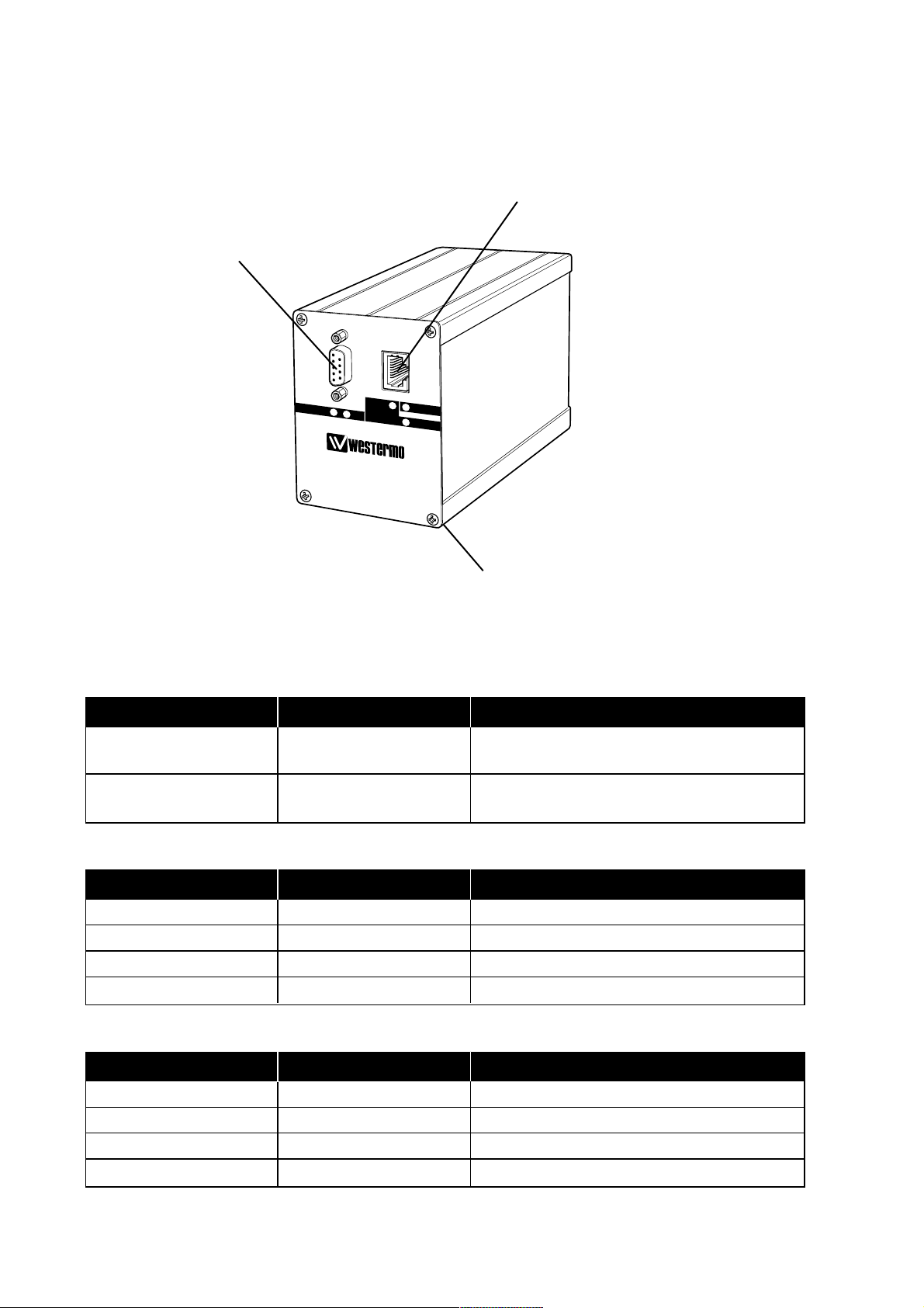
6.2 Connections
Profibus DP interface
9-pol D-sub, female
Ethernet/Service interface,
10Base-T, RJ-45 8-pin Modular Jack
Power interface
24 V DC
6.2.1 Power interface
6.2.2 Profibus DP interface
6.2.3 Ethernet/Service interface
Connection Description Note
Red conductor (+) +24 V DC From the units 2-pos screwblock
nearest the DIN-rail support
Black conductor (–) 0 V DC From the units 2-pos screwblock
nearest the front
Connection Direction Description
9-pos D-sub no.3 In/Out Receive/Transmit-Data-P (RxD/TxD-P)
9-pos D-sub no.5 – DGND
9-pos D-sub no.6 – +5V
9-pos D-sub no.8 In/Out Receive/Transmit-Data-N (RxD/TxD-N)
Connection Direction Description
RJ-45 no.1 Out Transmit data (TD+)
RJ-45 no.2 Out Transmit data (TD–)
RJ-45 no.3 In Receive data (RD+)
RJ-45 no.6 In Receive data (RD–)
DIAG
ER
-E
BA
POWER
STATUS
FD-80
FIELDBUS ADAPTER
PR
O
FIBUS D
P SLA
VE - TC
P/IP
Page 9

96630-2281
6.3 Indicators
6.3.1 LED indicators
DIAG: LED 1 sec blinking No transfer of Profibus DP data through
Ethernet.
LED 1/2 sec blinking Transfer of Profibus DP data through
Ethernet.
LED fast flashing FD-Tool configuration mode.
BA: LED on Profibus DP active.
LED off Profibus DP inactive/error.
ER-E: LED 1 x flashing FD-80 can’t receive a link pulse from a
hubport. Check the cable or hub port.
LED 2 x flashing Parity or framing error of internal serial
port. Check serial data format.
LED 3 x flashing Handshake error on internal serial port.
Check the handshake configuration.
Status: LED flashes Whenever there is activity on
Ethernet port.
LED off No activity on Ethernet port.
Power: LED on Correct internal power.
LED off No internal power.
ER-E, Status and Power: LEDs on Self-test error.
Page 10

10 6630-2281
6.4 Configuration
The device specific functionality and Profibus DP settings of FD-80 can be configured by
using FD-Tool (PC based software), either on-line or off-line.
The Ethernet network with TCP/IP protocol settings can be configured by using the
Telnet protocol.
6.4.1 DIP switch settings
The FD-80 has no DIP switch settings.
6.4.2 On-line configuration by FD-Tool
This part will only describe the usage of FD-Tool to perform the configuration.
For FD-Tool installation and general FD-Tool handling, see “FD-Tool installation manual”.
Service port of FD-80
The FD-80 goes into configuration mode (connection with FD-Tool) immediately
after a power on. The default setting of FD-80 service port, used for configuration
with FD-Tool is:
IP-address 10.0.0.10 Subnet mask 255.0.0.0 Port number 8000 Connection State FREE
These default settings can be modified before initiating communication between FD-Tool
and the FD-80, under Settings > Communication port and language settings >
TCP/IP.
Note 1: The IP-address and subnet mask can be changed by using Telnet, but to get access to
service port of FD-80 by FD-Tool, the IP-address and corresponding subnet mask has
to be the same as set by using Telnet.
Note 2: To get access to the service port, the FD-80 must be set to standard TCP/IP mode
(Connection state FREE), set by the Ethernet network configuration (see 6.4.5).
Note 3: The PC’s subnet mask setting must be the same as the FD-80 subnet mask setting,
but the PC’s IP-address must be different from the FD-80’s IP-address, to get access
to FD-80 by FD-Tool.
Initiate an on-line configuration
• Start the FD-Tool.
• Connect a crossover cable (or a straight cable if a switch/hub is used)
to the Ethernet-port of the PC and the service port of the FD-80.
• Initiate communication between the FD-Tool and the FD-80 by selecting Connect >
TCP/IP. The FD-80 will attempt to get communication until a successful connection
or a manual cancel.
• Power the connected FD-80. After some seconds, the connection will established and
the Status (to the left in the lower border of FD-Tool window) will be changed from
Disconnected to Connected.
• The FD-Tool shows the device type of this FD-80, present configuration, the default
configuration and whether or not the FD-80 is being used for the first time.
Page 11

116630-2281
Modify configuration
Configurations are defined per device type. see “Functional description”, chapter 7.
FD-80 P Point to point (P)
FD-80 A Addressed (A)
Load configuration to FD-80
• The present configuration, shown by FD-Tool, will be loaded to the FD-80 by selecting
File > Configuration > Load to device.
• This loaded configuration will be used by the FD-80 after a new power on.
6.4.3 Off-line configuration by FD-Tool
This part will only describe the usage of FD-Tool to perform an off-line configuration.
For FD-Tool installation and general FD-Tool handling, see “FD-Tool installation
manual.”
Initiate a new off-line configuration
• Start the FD-Tool.
• Select the device type by selecting File > Configuration > New (default / device) and
Select Group in the Device Selection window.
Note: The selected device must be the same as the FD-80 device, for which the configu-
ration will be used.
• Now the FD-Tool will show the device type of this FD-80 for which all configuration
parameters have to be set.
Modify configuration
Configurations are defined per device type. see “Functional description”, chapter 7.
FD-80 P Point to point (P)
FD-80 A Addressed (A)
Load configuration to FD-10
See, “On-line configuration by FD-Tool”, chapter 6.4.2.
6.4.4 Save, load and modify configuration files by FD-Tool
Save configuration to disk
• The present configuration can be saved to disk as a file, to be used for future
configurations of the same device type, by selecting
File > Configuration > Save to disk
• An arbitrary file name can be used, saved as a *.cnf file.
Load and modify a disk stored configuration
• Load configuration from disk by selecting Configuration > Load from disk and open
the required configuration file (*.cnf).
• FD-Tool shows the device type of this FD-80 with the present configuration.
Page 12

12 6630-2281
6.4.5 Ethernet network configuration by using Telnet
The FD-80 is always available for configuration of the TCP/IP protocol settings, by using
the Telnet network protocol. The default setting of FD-80 service port, for configuration
by using Telnet is:
IP-address 10.0.0.10 Subnet mask 255.0.0.0 Port number 1111
To select the configuration menu, start the Telnet client and use the parameters above,
e.g. under the DOS prompt enter Telnet <IP-address> 1111.
When the connection has been established you will see the following menu in your
Telnet window:
************************
* MINI Com-Server *
************************
1. INFO System
2. SETUP System
3. SETUP Port 0 (Serial)
4. Save Setup
Only one level at a time is shown on the monitor; enter a digit to scroll forward and
press ENTER to move backwards. All settings are activated only after a Save Setup. If
closing the Telnet connection without saving, the FD-80 retains all the settings it had
before opening the configuration menu. The following is an overview of the required
selections to be used by FD-80. The use of these selections are device and mode
dependent, to be described in chapters as follows:
FD-80 P Ethernet slave, Point to point continuously transfer mode See chapter 6.4.6
FD-80 P Ethernet slave, Point to point addressed mode See chapter 6.4.7
FD-80 A Ethernet master, addressed mode See chapter 6.4.8
6.4.5.1 Selections, used by FD-80
SETUP System > Setup TCP/IP
IP-Address IP-address setting of FD-80.
Subnet Mask Subnet mask of the subnet in which the FD-80 is located.
Gateway IP-address of the Gateway, used to get connections from FD-80 to
other subnets.
SETUP Port 0 (Serial) > Port State
Connection State Online control about the configured TCP/IP mode of the Ethernet
network connection. For access to FD-Tool it must be in mode
FREE, otherwise it has to be device and application dependent.
Clear Port Mode Revert the port to standard TCP/IP mode, FREE. This setting is
effective without Save Setup after exiting the menu.
Page 13

136630-2281
SETUP Port 0 (Serial)
UART Setup Settings of the internal serial port TCP/IP control interface, internal-
ly connected to the Profibus DP slave control. This is set by default
to 38,400 bit/s, no parity, 8 data bits and 1 stop bit, and should not
be changed while the internal serial port of Profibus DP slave control has the same default setting.
SETUP Port 0 (Serial) > TCP/IP Mode > Box to Box
Permanent TCP connection is opened between a Master and Slave port. It makes no difference which port is the Master and which the Slave. The Master port functions as a
TCP client and is therefore responsible for opening and closing.
Slave Port Port of the FD-80 Slave port, in range A to D and -. Only for the
master port, where it should be set to A.
Slave IP-Address IP-address of the FD-80, to which Slave port is located. This is set
only for Master port.
SETUP Port 0 (Serial) > TCP/IP Mode > IP Bus Mode
Several FD-80s logically linked together over the network in the
form of Master-Slave bus, where the Master sends data by broadcast and the Slaves send back data addressed to the Master. Any
additional data traffic or other network protocols have no effect on
the connection.
Master: Subnet IP Network address of the subnet in which the Master and Slaves are
located. This is set only for the Master.
Slave: Master IP IP-address of the Master. This is set only for the Slaves.
SAVE Setup
All changes will be saved in non-volatile memory. All settings are
activated only after a SAVE Setup. If closing the Telnet connection
without saving, the FD-80 retains all the settings it had before opening the configuration menu.
Page 14

14 6630-2281
6.4.6 Telnet configuration; Ethernet slave,
point to point with continuously transfer mode
Continuous transfer mode between two FD-80s by setting FD-80
(P) in box to box mode, one as master port and one as slave port.
FD-80; Master port
1. Set the IP-address of this FD-80 to <master IP-address>, and if needed the Subnet
mask and IP-address of the Gateway, select SETUP System > Setup TCP/IP.
2. Set the Port of the FD-80 Slave port to <A>, select SETUP Port 0 (Serial) >
TCP/IP Mode > Box to Box > Slave Port.
3. Set the IP-address of the FD-80 slave port to <slave IP-address>, select SETUP
Port 0 (Serial) > TCP/IP Mode > Box to Box > IP-Address.
4. Save all changes before closing the Telnet connection, select SAVE Setup.
FD-80; Slave port
1. Set the IP-address of this FD-80 to <slave IP-address>, and if necessary the Subnet
mask and IP-address of the Gateway, select SETUP System > Setup TCP/IP.
2. Check that the FD-80 port is set to standard TCP/IP mode, to <FREE>, select
SETUP Port 0 (Serial) > Port State > Connection State. If the port is not
set to FREE, the FD-80 can be set to standard TCP/IP mode, select SETUP Port 0
(Serial) > Port State > Clear Port Mode.
3. Save all changes before closing the Telnet connection, select SAVE Setup.
6.4.7 Telnet configuration; Ethernet slave,
point to point with addressed mode
This FD-80 is one slave in a Master-Slave network by setting the FD-80 (P)
in IP Bus mode.
1. Set the IP-address of this FD-80 to <slave IP-address>, and if necessary the Subnet
mask and IP-address of the Gateway, select SETUP System > Setup TCP/IP.
2. Set the IP-address of the Master to <master IP-address>, select SETUP Port 0
(Serial) > TCP/IP Mode > IP Bus Mode > Slave: Master IP.
3. Save all changes before closing the Telnet connection, select SAVE Setup.
6.4.8 Telnet configuration; Ethernet master,
addressed mode
This FD-80 is made the master in a Master-Slave network by setting the FD-80 (A)
in IP Bus mode.
1. Set IP-address of this FD-80 to <master IP-address>, and if necessary, the Subnet
mask and IP-address of the Gateway, select SETUP System > Setup TCP/IP.
2. Set the network address of the subnet in which the Master and Slaves are located to
<subnet address>, select SETUP Port 0 (Serial) > TCP/IP Mode > IP Bus
Mode > Master: Subnet IP.
3. Save all changes before closing the Telnet connection, select SAVE Setup.
Page 15

156630-2281
Technical data
Device type FD-80_P
GSD-file FD-80_P.gsd
Profibus DP
Input data Up to 8 modules, max 64 word data
Output data Up to 8 modules, max 64 word data
Ethernet
Transfer mode Slave, Point to point or Addressed mode
One Fieldbus Adapter at each side of the remote (modem) line, point to point.
Point to point mode:
One Fieldbus Adapter at each end of the Ethernet line, point to point. Continuous
modem transfer mode, where both units can initiate transfer. Continuously transfers
specified Profibus DP data from input/output buffer, via the modem interface. These
buffers are updated so the buffer at each side will be the same. However, note that
there will be a time delay which depends on transfer time.
Addressed mode:
Wait for received data with this unit’s transfer address, and then send back data frame
once.
No additional programming in the Profibus DP master (PLC) is required as the frames
between the slave adapters are automatically exchanged.
7. Functional description
7.1 Point to point FD-80 (P)
CHANNEL
4
I/O
FD-80
HUB HUB
FD-80
CHANNEL
4
I/O
Ethernet TCP/IP
Profibus DP
Profibus DP master Profibus DP master
Profibus DP
Page 16

16 6630-2281
7.1.1 Basic configuration
Serial transfer > Transfer mode
Point – point Select Transfer slave point to point mode, with serial
connection to one Fieldbus Adapter. The FD-80 will
initiate and begin continuous transfer of data with the
other Fieldbus Adapter.
Addressed slave Select Transfer slave in addressed mode, with connection
to one Fieldbus Adapter acting as transfer master.
The FD-80 will wait for received data (including address)
from the Fieldbus Adapter master and send back data
once.
Address Set this FD-80 Transfer mode address, in range 1–64.
Only needed when Addressed slave has been selected.
Profibus-DP > Profibus DP parameters
Profibus DP Address Set this FD-80 Profibus DP address.
Number of I/O Modules Set the number of I/O modules used by this FD-80.
The used I/O modules will be from 1 up to the chosen
“Number of I/O Modules”.
I/O module 1–4 > I/O module 1
Data type Select data type for I/O module 1.
Module type Select module type for I/O module 1.
Data length Set data length for I/O module 1. Note that data length
is related to data type. The byte has a length of 8 bit and
word has a length of 16 bits.
Identifier Show the resulting identifier in hex.
The same content for all I/O modules, 1 to 8. The used I/O modules will be from 1 and
up to the chosen “Number of I/O Modules”.
Page 17

176630-2281
7.1.1.1 Expert configuration
Serial transfer > Expert parameters
Serial interface Select the desired parameters of the internal interface of
Profibus DP Slave control. Set to 38,400 bit/s 8 data bits,
no parity and 1 stop bit, and will not be changed.
Delay to send first byte Set the delay time before switching from send to receive
frame or vice versa. Default is 0. Used when the line
requires a turning time.
Max time between bytes Set the maximum allowed time between bytes in a frame.
Default is 100. Useful when a frame will be divided by
transferring units which can cause a gap in parts of the
frame. Shall be less than “Min random delay at initiation”.
Min/max random delay Create a random delay until sending the initial frame in
at initiation point to point mode, to avoid collisions after start up and
disturbed communication.
Default is min 200 and max 500.
Fixed frame length Fixed 25 byte frame length. Should not be used.
20 data bytes Only when used together with old system.
Fixed frame length Fixed 37 byte frame length. Should not be used.
32 data bytes Only when used together with old system.
Variable frame length Should be selected for all Westermo Fieldbus Adapters.
1..126 data bytes
Profibus-DP > Expert parameters
Modem retries until set The number of consecutive sent initial frames
Stat Diag before setting of the Profibus DP diagnostic information
Stat_Diag (static diagnostics). Default is 3. Can be
increased if transmission line is disturbed and that is
acceptable.
ID number Show the ID number of the FD-80. Can’t be changed.
CPU type Hardware information. For service purpose only.
Can’t be changed.
7.1.2 Profibus DP I/O data
Ordinary Profibus DP input and output data is used by FD-80 (P).
Page 18

18 6630-2281
Technical data
Device type FD-80_A
GSD-file FD-80_A.gsd
Profibus DP
Input data Up to 8 modules, max 64 word data
(include 1 word status)
Output data Up to 8 modules, max 64 word data
(include 1 word command)
Ethernet
Addressable slaves Max 64
Transfer mode Master, Addressed mode
Ethernet TCP/IP
Profibus DP Profibus DP Profibus DP Profibus DP
CHANNEL
4
FD-80 (A)
HUB
Profibus DP master
CHANNEL
4
FD-80 (P)
HUB
Profibus DP master
HUB
FD-80 (P)
CHANNEL
4
Profibus DP master
CHANNEL
4
FD-80 (P)
HUB
Profibus DP master
7.2 Addressed FD-80 (A)
One FD-80 (A) at the local side communicates with one or many addressed FD-80 (P)
at the remote side.
Master – slave transfer mode, where FD-80 (A) is the master which initiates the transfer.
It transfers specified Profibus DP data from the input /output buffer, via Ethernet, on
demand from a Profibus DP master.
The data frames include the transfer slave address of the selected remote FD-80 (P).
The remote FD-80 (P) units are transfer slaves, which wait for received frames including
the correct slave address, before sending back one frame to the FD-80 (A).
Additional programming in the Profibus DP master (PLC)is needed, such as addressing,
transfer control and check.
Page 19

196630-2281
7.2.1 Basic configuration
Profibus-DP >Profibus DP parameters
Profibus DP Address Set this FD-10 Profibus DP address.
Number of I/O Modules Set the number of I/O modules used by this FD-10.
The used I/O modules will be from up to the chosen
“Number of I/O Modules ”.
I/O module 1 –4 >I/O module 1
Data type Select data type for I/O module 1.
Module type Select module type for I/O module 1.
Data length Set data length for I/O module 1.Note that data length is
related to data type. The byte has a length of 8 bits and
the word has a length of 16 bits.
Identifier Show the resulting Identifier in hex.
The same content for all I/O modules,1 to 8.The used I/O modules will be from 1 up to
the chosen “Number of I/O modules ”.
7.2.1.1 Expert configuration
Serial transfer >Expert parameters
Serial interface Select the desired parameters of the internal interface of
Profibus DP Slave control. Set to 38,400 bit/s, 8 data bits,
no parity and 1 stop bit, and will not be changed.
Max time between bytes Set the maximum allowed time between bytes in a frame.
The default is 100. Used to allow a frame to be divided
by the modem line.
Serial transfer master address Not used.
Fixed frame length Fixed 25 byte frame length. Should not be used.
20 data bytes Only when used together with old system.
Fixed frame length Fixed 37 byte frame length. Should not be used.
32 data bytes Only when used together with old system.
Variable frame length Should be selected for all Westermo Fieldbus Adapters.
1..126 data bytes
Profibus-DP >Expert parameters
ID number Show the ID number of FD-10. Can ’t be changed.
CPU type Hardware information. For service purpose only.
Can’t be changed.
7.2.2 Profibus DP I/O data
Ordinary Profibus DP input and output data are used by FD-80 (A), with one additional
serial transfer command word at “out data”, and one status word at “in data”.
Page 20

20 6630-2281
Word 15 High byte 8 7 Low byte 0
1 EN SDO – CNF RES – – – Transfer slave address, in range 1–64
2 Out word 1, high byte Out word 1, low byte
–– –
–– –
64 Out word 63, high byte Out word 63, low byte
7.2.2.1 Output data word
Data transmitted from Profibus DP master to FD-80. The first word is the added command word and the remaining 1 to 63 words are ordinary output data sent to the
addressed remote Fieldbus Adapter.
Output word 1 high byte (bit 15..8) is the serial transfer command byte, with following
content:
EN ENable the FD-80 (bit15).
This bit must always be set high (1) for normal operation.
When it is set FD-80 indicates data set ready by the EN
bit being set in the Input status word. The EN bit is only
set to low (0) to disable the FD-80.
SDO Send actual Data Once, toggle bit (bit 14).
When this toggle bit is changed, the data words are
taken from the DP data words and transmitted directly
over the serial transfer interface of the FD-80.
CNF CoNFiguration mode (bit 12).
For testing purpose only.
This bit is set low (0) during the normal operating mode
of the FD-80. This bit is set high (1) in order to switch
the FD-80 over from normal operating mode to configuration mode.
RES RESet read back status, toggle bit (bit 11).
When this toggle bit is changed, it will reset read back
status ACK and TO also in all data words.
Output word 1 low byte (bit 7..0) is the serial transfer address, with the following content:
Transfer slave address of the Fieldbus Adapter to which this frame will be sent. Serial
transfer slave address, range is 1 to 64.
Output word 2 to 64 is the output data, with following content:
Word 1 High: Output byte 1 Low: Output byte 2
Word 2 High: Output byte 3 Low: Output byte 4
......... ......... ........
Word 63 High: Output byte 125 Low: Output byte 126.
Page 21

216630-2281
Word 15 High byte 8 7 Low byte 0
1 ST – DV – ACK TO – – – – – – – – – –
2 In word 1, high byte In word 1, low byte
–– –
–– –
64 In word 63, high byte In word 63, low byte
7.2.2.2 Input data word
Data is transmitted from the FD-80 to the Profibus DP master. The first word is the
added status word and the remaining 1 to 63 words are ordinary input data received
from the output word addressed remote Fieldbus Adapter.
Input word 1 high byte (bit 15..8) is the serial transfer status byte, with following content:
ST STatus of serial transfer command FD-80 (bit15).
Set to high (1) when the received command has been
accepted by the FD-80. Set to low (0) if the received
command has not been accepted.
DV Data Valid (bit 13).
For testing purpose only.
Acknowledgement of the command CNF.
ACK ACKnowledgement of serial transfer (bit 11).
Set to high (1) when serial transfer sent output data to a
remote FD-80 has resulted in a received frame with input
data from the remote FD-80.
TO Time Out of serial transfer (bit 10).
Set to high (1) when the last serial transfer of output
data to a remote FD-80 has not resulted in any received
frame within 1,500 ms.
Input word 1 low byte (bit 7..0) is not used.
Input word 2 to 64 is the input data, with following content:
Word 1 High: Input byte 1 Low: Input byte 2
Word 2 High: Input byte 3 Low: Input byte 4
........ ......... .......
Word 63 High: Input byte 125 Low: Input byte 126.
Page 22

22 6630-2281
7.2.2.3 Profibus DP communication
This describes the required Profibus DP communication sequence, from a Profibus DP
master unit to FD-80 (A), to get access and data exchange with remote Fieldbus
Adapters.
Preparing for data exchange:
1. Enable normal operation access with FD-10 by command EN
Out word 1, bit 15.
2. Verify accepted EN command by checking status ST.
In word 1, bit 15.
Data exchange with a remote Fieldbus Adapter :
1. Set the Transfer slave address.
Out word 1, low byte.
2. Set Out data (up to 63 word) to this Transfer slave.
Out word 2 ...64.
3. Reset last received Input data and status by the command RES.
Out word 1, toggle bit 11.
4. Transmit output data over serial transfer line by the command SDO.
Out word 1, toggle bit 14.
5. Verify correct sent and received data by checking status ACK.
In word 1, bit 11 is high (1). Alternatively, incorrect sent and received data,has not
been received within 1,500 ms by checking status TO.
In word 1, bit 10 is high (1).
6. If correct received data (ACK OK)
Read In data (up to 63 word) from this Transfer slave TO.
In word 2 ...64.
Page 23

Page 24

T03-0155 • 6630-2281 03.03 Mälartryck AB, Eskilstuna, Sweden
Westermo Teleindustri AB • SE-640 40 Stora Sundby,Sweden
Phone +46 16 42 80 00 Fax +46 16 42 80 01
E-mail:info@westermo.se • W estermo W eb site: www.w estermo.se
Westermo Teleindustri AB have distributor s in several
countries, contact us for fur ther information.
Westermo Data Communications Ltd
Unit 14 Talisman Business Centre • Duncan Road
Park Gate, Southampton • SO31 7GA
Phone:+44(0)1489 580 585 • Fax.:+44(0)1489 580586
E-Mail:sales@westermo.co.uk • Web:www.westermo.co.uk
Westermo Data Communications GmbH
Goethestraße 67,68753 Waghäusel
Tel.: +49(0)7254-95400-0 • Fax.:+49(0)7254-95400-9
E-Mail:info@westermo.de • Web:www.westermo.de
Westermo Data Communications S.A.R.L.
9 Chemin de Chilly 91160 CHAMPLAN
Tél :+33 1 69 10 21 00 • Fax : +33 1 69 10 21 01
E-mail :infos@westermo.fr • Site WEB: www.westermo.fr
Subsidiaries
Application example
Profibus master
Profibus DP
Profibus DP
Profibus DP
Profibus master
Profibus master
Ethernet
TCP/IP
FD-80 FD-80
FD-80
 Loading...