

Page 1

Fieldbus Converter
INSTALLATION MANUAL
6630-2242
www.westermo.com
FD-40
©
W estermo T eleindustri AB • 2003 • REV.A
Page 2

Page 3

36630-2242
Contents
1. Safety .................................................................................................................................................................................. 4
2. Approvals ....................................................................................................................................................................... 4
2.1. Declaration of Conformity ..................................................................................................................... 5
3. Introduction ............................................................................................................................................................... 6
3.1 Field of application ....................................................................................................................................... 6
4. Specifications ............................................................................................................................................................ 7
4.1 Interfaces .............................................................................................................................................................. 7
4.2 Insulation between interfaces .............................................................................................................. 8
4.3 Climatic environment ................................................................................................................................ 8
4.4 Mechanics ............................................................................................................................................................. 8
5. Maintenance .............................................................................................................................................................. 9
6. Installation ................................................................................................................................................................... 9
6.1 Mounting /Removal ...................................................................................................................................... 9
6.2 Connections .................................................................................................................................................... 12
6.2.2 Power ........................................................................................................................................................ 10
6.2.3 PROFIBUS DP ................................................................................................................................... 11
6.2.4 RS-232 (DTE) ..................................................................................................................................... 11
6.2.5 RS-485 ...................................................................................................................................................... 11
6.3 Indicators .......................................................................................................................................................... 12
6.3.1 LED indicators ................................................................................................................................... 12
6.4 Configuration ................................................................................................................................................. 12
6.4.1 DIP switch settings ............................................................................................................... 12–13
6.4.2 On-line configuration by FD-Tool ....................................................................................... 14
6.4.3 Off-line configuration by FD-Tool ....................................................................................... 15
6.4.4 Save,load and modify configuration files by FD-Tool ......................................... 15
7. Functional description .............................................................................................................................. 16
7.1 Point to point and Addressed,serial transfer slave, FD-10 P .................................... 16
7.1.1 Basic configuration ........................................................................................................................ 17
7.1.1.1 Expert configuration ......................................................................................................... 17
7.1.2 PROFIBUS DP I/O data ............................................................................................................. 17
7.3.2.1 Output data word ...................................................................................................... 17–19
7.3.2.2 Input data word ............................................................................................................ 19–20
7.3.2.3 PROFIBUS DP communication ...................................................................... 21–22
Page 4

4 6630-2242
1. Safety
General:
Before using this unit,read this manual completely and gather all information on
the unit.Make sure that you understand it fully.Check that your application does
not exceed the safe operating specifications for this unit.
Before installation,maintenance or modification work:
Prevent damage to internal electronics from electrostatic discharges (ESD)
by discharging your body to a grounding point (e.g. use of wrist strap).
Prevent access to hazardous voltages by disconnecting the unit from AC/DC
mains supply and all other electrical connections.
Installation:
This unit should only be installed by qualified personnel.
This unit should only be installed in a “restricted access area”,for example
a lockable cabinet where access is restricted to service personnel only.
This unit is intended for permanent connection to the AC/DC mains supply.
The power supply wiring must be sufficiently fused, and if necessary it must be
possible to disconnect manually from the AC/DC mains supply. Ensure compliance
to national installation regulations.
Unit with the rated voltage exceeding 42.4 V peak or 60 VDC , is defined as class I
equipment with a protective earthing conductor terminal.
Unit with the rated voltage up to 42.4 V peak or 60 VDC , is defined as class III
equipment and shall be separated from hazardous voltage by double or reinforced
insulation.
This unit uses convection cooling.To avoid obstructing the air flow around the
unit,follow the spacing recommendations (see under chapter Installation).
2. Approvals
Conformity with the Directive 89/339/EEC (Electromagnetic compatibility)
has been assessed by application of standards EN 61000-6-2 (industrial immunity)
and EN 61000-6-4 (industrial emission).
!
!
!
Page 5
56630-2242
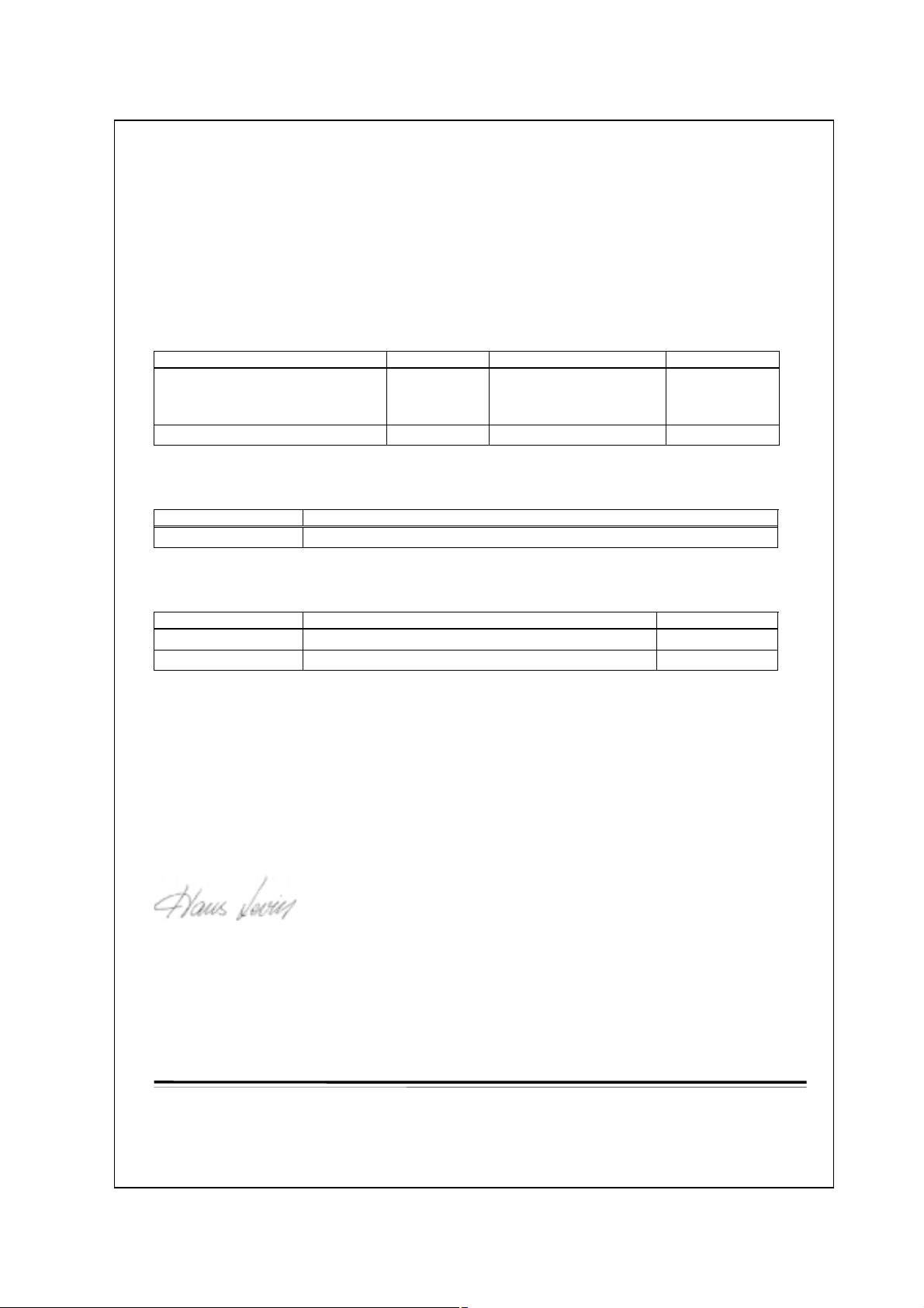
2.1. Declaration of Conformity
e
Westermo Teleindustri AB
Declaration of conformity
The manufacturer Westermo Teleindustri AB
SE-640 40 Stora Sundby, Sweden
herewith declares that the product(s)
Type of product Model Art no Installation manual
DIN-rail Fieldbus adapter FD-10 P
FD-10 A
FD-10 N
DIN-rail Fieldbus converter FD-40 3630-1400 6630-2242
is in conformity with the following EC directive(s).
No Title
89/336/EEG Electromagnetic Compatibility (EMC-directive)
3630-1100
3630-1101
3630-1102
6630-2212
References of standards applied for this EC declaration of conformity.
No Title Issue
EN 61000-6-2 Immunity for industrial environments 2 (2001)
EN 61000-6-4 Emission standard for industrial environments 1 (2001)
Hans Levin
Technical Manager
26th May 2003
Postadress/Postal address Tel. Telefax Postgiro Bankgiro Corp. identity number Registered office
S-640 40 Stora Sundby 016-61200 016-61180 52 72 79-4 5671-5550 556385-6367 Eskilstuna
Sweden Int+46 1661200 Int+46 1661180
Org.nr/ S‰t
Page 6
6 6630-2242
3.1 Field of application
3. Introduction
The FD-40 Fieldbus Converter integrates devices using the serial interfaces RS-232
or RS-485 into PROFIBUS DP.
The FD-40 works as a PROFIBUS DP slave and enables the utilisation of normal
PROFIBUS DP I/O data for transparent communication over a serial interface.
The FD-40 enables the integration of systems such as measuring devices,electronic
scales,operator terminals, printers,identification systems, barcode readers and other
automation devices which use a RS-232 or RS-485 interface into PROFIBUS DP
applications. While FD-40 have 15 kbyte input and output buffers,a huge amount
of data or a high data rate can be transferred over the serial interface without
disturbing the PROFIBUS DP traffic.
In data
PROFIBUS DP
In buffer
15k
Serial transfer
PROFIBUS DP
Master control
Interface
Serial transfer
control
Out data
PROFIBUS DP
Out buffer
15k
Serial T ransfer
RS-232
RS-485
Power
DC
DC
PROFIBUS DP
• Receive data from bar code readers
• Interface to operator terminals
• Send data to viewing screens
• Interface to transmitters with serial interface
PROFIBUS DP
slave
PROFIBUS DP RS-232/485
PROFIBUS DP
master (PLC)
FD-40 B
Text display
Page 7

76630-2242
4. Specifications
4.1 Interfaces
Power
Rated voltage 12–48 VDC
Operating voltage 9.6–57.6 VDC
Rated current 250 mA @ 12 V,120 mA @ 24 V, 60 mA @ 48 V
Rated frequency DC
Polarity Reverse polarity protected
Connection Screw terminal
Connector size 0.2–2.5 mm
2
(AWG 24–12)
Fuse To be externally fused
PROFIBUS DP
Electrical specification RS-485/V.11 / EN 50 170
Data rate 9.6, 19.2,45.45, 93.75,187.5, 500, 1 500,3 000, 6 000
and 12 000 kbit/s
Connection 9-position D-sub (female)
Termination External
Circuit type TNV-1
RS-485
Electrical specification RS-485/V.11
Data rate 1 200,2 400, 4 800,9 600, 14 400, 19 200 and 38 400 bit/s
Data format 7/8 data bits,no/odd/even parity, 1/2 stop bits
Connection 2-position screw terminal
Connector size 0.2 – 2.5 mm
2
(AWG 24-12)
Circuit type TNV-1
RS-232
Electrical specification RS-232/V.24
Data rate 1 200,2 400, 4 800,9 600, 14 400, 19 200 and 38 400 bit/s
Data format 7/8 data bits,no/odd/even parity, 1/2 stop bits
Connection 9-position D-sub,DTE
Circuit type SELV
Page 8

8 6630-2242
4.2 Insulation between interfaces
Power to all other 1.0 kV RMS @ 50Hz and 60 s duration
PROFIBUS DP to all other 1.0 kV RMS @ 50Hz and 60 s duration
Please note that there is no galvanic isolation between the RS-232 and the RS-485 ports
so they should not be connected simultaneously.
Internal
electronics
Power
PROFIBUS DP
RS-485
RS-232
NOTE:
Connect only one of RS-232
or RS-485 simultaneously
4.3 Climatic environment
Temperature, operating +5 to +55°C (optional industrial –25 to +70°C)
Temperature,
storage and transportation –25 to +70°C
Relative humidity, operating 5 to 95% (non-condensing)
Relative humidity,
storage and transportation 5 to 95% (condensation allowed outside packaging)
4.4 Mechanics
Dimension (W x H x D) 55 x 100 x 132 mm
Weight 0.3 kg
Mounting 35 mm DIN-rail
Degree of protection IP 20 (IEC 529)
Page 9

96630-2242
5. Maintenance
No maintenance is required, as long as the unit is used as intended within the specified
conditions.
6. Installation
6.1 Mounting /Removal
Before mounting or removing the unit:
Prevent damage to internal electronics from electrostatic discharges (ESD)
by discharging your body to a grounding point (e.g. use of wrist strap).
Prevent access to hazardous voltages by disconnecting the unit from AC/DC
mains supply and all other electrical connections.
Mounting
This unit should be mounted on 35 mm DIN-rail which is
horizontally mounted on a wall or cabinet backplate.
This unit uses convection cooling. To avoid obstructing the air
flow around the unit, use the following spacing rules.
Minimum spacing 25 mm (1.0 inch) above/below and 10 mm
(0.4 inches) left/right the unit.
Snap on mounting, see figure.
Removal
Press down the black support at the back of the unit
using a screwdriver, see figure.
Min
10 mm
25 mm
25 mm
!
CLICK!
Page 10

10 6630-2242
6.2 Interfaces
RS-232
PROFIBUS DP
RS-485
Power
Page 11

116630-2242
2-pos screw terminal Direction Description
No.1 – 0 V DC (–)
No.2 + +12 to +48 VDC (+)
6.2.2 Power
9-pos D-sub Direction Description
No.1 ––
No.2 ––
No.3 In/Out RxD/TxD-P
No.4 Out CNTR-P
No.5 – DGND
No.6 Out VP
No.7 ––
No.8 In/Out RxD/TxD-N
No.9 – DGND
6.2.3 PROFIBUS DP
9-pos D-sub Direction Description
No.1 ––
No.2 In Receive Data (RD)
No.3 Out Transmit Data (TD)
No.4 Out Data Terminal Ready (DTR)
No.5 – Signal ground (SG)
No.6 ––
No.7 Out Request To Send (RTS)
No.8 In Clear To Send (CTS)
No.9 ––
6.2.4 RS-232 (DTE)
1
2
2-pos screw terminal Direction Description
No.1 In/Out T ransmit/Receive T/R+ (T+)
No.2 In/Out T ransmit/Receive T/R– (T–)
6.2.5 RS-485
1
2
5
4
3
2
1
9
8
7
6
1
2
3
4
5
6
7
8
9
Female
Male
Page 12

12 6630-2242
6.3 Indicators
6.3.1 LED indicators
6.4 Configuration
Most of the FD-40 settings have to be carried out by FD-Tool,a PC based configuration
software,either on-line or off-line. Only RS-232 or RS-485 transfer settings will be set by
DIP switches.
6.4.1 DIP switch settings
DIP-switches are accessible under the lid on top of the unit.
Warning! Prevent damage to internal electronics from electrostatic discharges
(ESD)
by discharging your body to a grounding point (e.g. use of wrist
strap),before the lid on top of the modem is removed.
Warning! Do not open connected equipment.
Prevent access to hazardous voltages by disconnecting the unit from
AC/DC mains supply and all other electrical connections.
NOTE The change of DIP switch settings are valid only after a power on.
PWR LED on In service
LED off Out of service
BA LED on PROFIBUS DP active
LED off PROFIBUS DP inactive
CONF LED on Configuration mode
LED off Normal operation mode
TD LED on Transmit serial (RS-232/485) data
LED off –
RD LED on Receive serial (RS-232/485) data
LED off –
RTS LED on Request To Send (RTS) set
LED off –
CTS LED on Clear To Send (CTS) received active
LED off –
!
!
Page 13

136630-2242
Switch block 1
Serial transfer setting
Factory setting
S2:1-8
ON
1234
No RS-485 termination
ON
1234
RS-485 terminated by
120 Ω, with fail-safe
ON
1234
RS-232 selected as serial
transfer port, data control
ON
1234
RS-232 selected as serial
transfer port, RTS/CTS control
ON
1234
S1
RS-232 selected as serial
transfer port, data control.
No RS-485 termination
ON
1234
RS-485 selected as serial
transfer port
Note 1: Configuration by FD-Tool require factor y setting (all S1 switches off).
Note 2: Switch 2 is not used.
S1:1-4
Page 14

14 6630-2242
6.4.2 On-line configuration by FD-Tool
This part will only describe the usage of FD-Tool to perform an on-line configuration.For
FD-Tool installation and general FD-Tool handling,see “FD-Tool installation manual” on
the CD, FD-Tool.
The FD-40 goes into configuration mode, a connection with FD-Tool, immediately after a
power on.The serial interface is set as follows, and should not be changed.
RS-232 9 600 bit/s no parity 8 data bits 1 stop bit data control
Initiate an on-line configuration
• Start the FD-Tool.
• Connect a DTE-DTE serial cable (zero-modem) to the serial port of the PC and the
RS-232 port of the FD-40.
• Initiate communication between the FD-Tool and the FD-10 by selecting Connect >
RS-232.The FD-Tool will attempt to get communication until a successful connection
or a manual cancel.
• Power the connected FD-40.The CONF LED of FD-40 will be active and remain so as
long as the FD-40 is in configuration mode. After some seconds, the connection will
established and the Status (to left in lower border of FD-Tool window) will be changed
from Disconnected to Connected.If the CONF LED will be inactive (after about
3 seconds),the initiation of on-line configuration is failed. If failed,check the serial
cable and that all S1 switches are set to off.Power on the device again.
• The FD-Tool shows the device type of this FD-40,present configuration,or the default
configuration whether the FD-40 is used for the first time.
Modify configuration
Configurations are defined per device type,see “Functional description”,chapter 7.
FD-40 B Buffered
Load configuration to FD-40
• The present configuration,shown by FD-Tool,will be loaded to the FD-40 by selecting
File > Configuration > Load to device.
• This loaded configuration will be running in normal operation after a new power on
and when the CONF LED has been set to inactive.
Page 15

156630-2242
6.4.3 Off-line configuration by FD-Tool
This part will only describe the usage of FD-Tool to perform an off-line configuration.
For FD-Tool installation and general FD-Tool handling, see “FD-Tool installation manual.”
Initiate a new off-line configuration
• Start the FD-Tool.
• Select the device type by selecting File > Configuration > New (default / device)
and Select Group in Device Selection window. The selected group has to be the same
as the FD-40 device,for which the configuration will be used.
• FD-Tool will show the device type of this FD-40 for which all configuration parameters
have to be set.
Modify configuration
Configurations are defined per device type,see “Functional description”,chapter 7.
FD-40 B Buffered
Load configuration to FD-40
• See “On-line configuration by FD-Tool”,chapter 6.4.2.
6.4.4 Save, load and modify configuration files by FD-Tool
Save configuration to disk
• The present configuration can be saved to disk as a file, to be used for future configurations of the same device type,by selecting File > Configuration > Save to disk
• An arbitrary file name can be used, saved as a *.cnf file.
Load and modify a disk stored configuration
• Load configuration from disk by selecting Configuration > Load from disk
and open the wanted configuration file (*.cnf).
• FD-Tool shows the device type of this FD-40 with the present configuration.
Page 16

16 6630-2242
FD-40 B
Device type
GSD-file FD-10.GSD
Device type Slave
Address range 0 to 126
Number of modules 2
Input data 4 word complete consistency
Output data 4 word complete consistency
Data control One word for serial transfer control
7. Functional description
Technical data
PROFIBUS DP data
Device
7.1 Buffered,FD-40 B
Functions that are included in the FD-40 B:
1. Send some bytes of data direct to the serial interface
Send up to 6 byte data from PROFIBUS DP to the serial interface
2. Send data to buffer and finally send buffered data to the serial interface
once
Send up to 6 byte PROFIBUS DP data in time to the send buffer. By command can
these buffered data be sent to the serial interface.Up to 15 kbyte can be sent once.
3. Receive buffered data,from serial interface received data
Data received from serial interface will automatically be stored in the receive buffer.
These data will be picked up by PROFIBUS DP, 6 byte each time.
All these three functions are ready to use without any modification by the
configuration tool.
FD-40 can convert PROFIBUS DP data over the serial interface when the unit is in
normal operation mode and the PROFIBUS DP is active, LED CONF inactive and
BA active.
Page 17

176630-2242
7.1.1 Basic configuration
Serial > Serial interface
Select the desired parameters of the Serial interface.
PROFIBUS-DP > PROFIBUS DP parameters
Profibus DP Address Set this FD-40 PROFIBUS DP address.
7.1.1.1 Expert configuration
PROFIBUS-DP > Expert parameters
Timeout, new Set the maximum time as entered PROFIBUS DP in data
PROFIBUS DP data (ms) will be seen as new. Default is 500.
ID number Show the ID number of the FD-40. Can’t be changed.
I/O module 1–2 > I/O module 1
Identifier [hex] Show the 4 word input Identifier in hex.
Can’t be changed.
I/O module 1–2 > I/O module 2
Identifier [hex] Show the 4 word output Identifier in hex.
Can’t be changed.
7.1.2 PROFIBUS DP I/O data
Ordinary 4 word PROFIBUS DP I/O data are used by FD-40, including one data word
in and one out for the serial interface control. Additional programming of the
PROFIBUS DP master is needed to control I/O data interfacing to the serial port,
as defined below.
7.3.2.1 Output data word
Data transmitted from PROFIBUS DP master to FD-40. The first word is the command
word and the remaining 3 words are ordinary output data to be temporarily stored in
the transmit buffer or directly transmitted via the serial interface.
Word 15 High byte 8 7 Low byte 0
1 EN SDO SFB CNF CTB OL2 OL1 OL0 RNB RAK RBS – – – – –
2 Out data byte 1 Out data byte 2
3 Out data byte 3 Out data byte 4
4 Out data byte 5 Out data byte 6
Page 18

18 6630-2242
Output word 1 (bit 15...5) are the serial transfer command bits,
with the following content:
EN ENable FD-40 (bit15).
This bit must always be set high (1) for normal operation.
EN bit set to low (0) disable FD-40.
SDO Send actual Data Once, toggle bit (bit 14).
When this toggle bit change state, the number of output data bytes defined
by DL2-DL0 are taken from Profibus DP out data and transmitted directly
over the serial interface.
SFB Send data from transmit buffer, toggle bit (bit 13).
When this toggle bit change state, the content of the transmit buffer will
be continuously transmitted over the serial interface. During transmission
the Transmission Busy status (TXB) will be set to high (1).
Write acknowledge status (WAK) will be changed at transmission
of the first character.
CNF CoNFiguration mode (bit 12).
This bit must always be set low (0) for normal operation.
CTB Copy to Transmit Buffer, toggle bit (bit 11).
When this toggle bit change status, Out data Length (OL2-0) characters
of PROFIBUS DP out data (out data 1–6) will be transferred to the
transmit buffer. Before change state of CTB, the PROFIBUS DP out data
(out data 1–6) and Data Length (OL2-0) must be set.
OL2 Out data Length bit 2 (bit 10).
Bit 2 of the PROFIBUS DP out data length.
OL1 Out data Length bit 1 (bit 9).
Bit 1 of the PROFIBUS DP out data length.
OL0 Out data Length bit 0 (bit 8).
Bit 0 of the PROFIBUS DP out data length.
E.g. For 6 characters PROFIBUS DP out data OL2, OL1 will be high (1)
and OL0 low (0).
RNB Read Next Block (bit 7).
At the low to high transition of this command, the first data block of the
receive buffer will be fetched and written into Profibus DP in data. The In
data Length (IL2-0) defines the number of fetched characters. The Profibus
DP in data is valid when the command is acknowledged by change state of
BLock Ready (BLR).
At the high to low edge of this command, clear the first data block area of
the receive buffer and reset the In data Length (IL2-0).
RAK Read AcKnowledge, toggle bit (bit 6).
This bit will always be set low (0) for normal operation.
Only used when compatibility with earlier product
versions is needed.
Page 19

196630-2242
RBS Reset Buffers and Status signals (bit 5).
At the low to high transition of this command, the receive and
transmit buffers and the status signals RBO, TBO and DEX are cleared.
The command is acknowledged by change state of BLock Ready (BLR).
After state of BLR has been changed, RBS will be set to low (0) again.
Output word 1 (bit 4...0) are not used
These bits will always be set to 0.
Output word 2 to 4 is the output data, with following content:
Word 2 High: Out data byte 1 Low: Out data byte 2
Word 3 High: Out data byte 3 Low: Out data byte 4
Word 4 High: Out data byte 5 Low: Out data byte 6
7.1.2.2 Input data word
Data is transmitted from the FD-40 to the PROFIBUS DP master. The first word is the
added status word and the remaining 3 words are ordinary input data from the receive
buffer.
Word 15 High byte 8 7 Low byte 0
1 VAL TXB TBO RBO DPN IL2 IL1 IL0 BLR WAK ERR DEX – – – –
2 In data byte 1 In data byte 2
3 In data byte 3 In data byte 4
4 In data byte 5 In data byte 6
Input word 1 (bit 15...4) are the serial transfer status bits, with following content:
VAL FD-40 VALid (bit15).
Set to high (1) when the FD-40 is in normal operation.
Set to low (0) when the receive buffer is full or if data received from serial
interface has wrong polarity.
TXB TX Busy (bit 14).
Set to high (1) as long as data is transmitted by the serial interface,
directly or from the transmit buffer.
TBO Transmit Buffer Overflow (bit 13).
Set to high (1) as long as transmit buffer has less than 6 bytes free.
RBO Receive Buffer Overflow (bit 12).
Set to high (1) when the receive buffer has less than 15 bytes free.
Reset to low (0) when the receive buffer has more than 100 bytes free.
Page 20

20 6630-2242
DPN PROFIBUS DP New (bit 11)
Normally not used, but can serve as support for evaluating the age of
wanted data.
Set to high (1) when a data block of the receive buffer has been fetched
and written into PROFIBUS DP in data. Automatically reset to low (0)
after timeout, the maximum time entered PROFIBUS DP in data will be
seen as new. This timeout is set by the parameter “Timeout, new
PROFIBUS DP data, by the configuration tool FD-Tool.
IL2 In data Length bit 2 (bit 10)
Bit 2 of the PROFIBUS DP in data length.
IL1 In data Length bit 1 (bit 9)
Bit 1 of the PROFIBUS DP in data length.
IL0 In data Length bit 0 (bit 8)
Bit 0 of the PROFIBUS DP in data length.
E.g. For 6 characters PROFIBUS DP in data will IL2, IL1 be high (1)
and IL0 low (0).
BLR Block Ready, toggle bit (bit 7)
This toggle bit change state, to acknowledge when the command RNB
or RRB (and CNF and RAK if any of these are used) have been finished
successfully.
WAK Write AcKnowledge, toggle bit (bit 6)
This toggle bit change state, to acknowledge the command CTB,
SDO or SFB.
ERR ERRor (bit 5)
Set to high (1) when the last received command or it’s parameters were
illegal.
Set to low (0) when receiving a correct command.
DEX Data EXist (bit 4)
Set to high (1) as long as the receive buffer contains data received by the
serial interface.
Reset to low (0) by the command Read Next Block (RNB) when the
receive buffer is empty.
Input word 1 (bit 3...0) are not used.
Input word 2 to 4 is the input data, with following content:
Word 2 High: In data byte 1 Low: In data byte 2
Word 3 High: In data byte 3 Low: In data byte 4
Word 4 High: In data byte 5 Low: In data byte 6
Page 21

216630-2242
7.3.2.3 PROFIBUS DP communication
This describes the required PROFIBUS DP communication sequence from a PROFIBUS DP
master to an FD-40 B, to get access and data exchange with the serial interface of FD-40.
Preparing for all type of data exchange:
1. Enable normal operation by command EN.
Out word 1, bit 15 set high (1).
2. Check that FD-40 is in normal operating condition by checking status VAL.
In word 1, bit 15 should be high (1).
Send PROFIBUS DP out data direct (up to 6 byte) to serial interface:
1. Write PROFIBUS DP out data word 2–4 to be sent from serial interface.
Out word 2–4.
2. Set Out data length OL2, OL1 and OL0.
Out word 1 bit 10–8.
3. Check that serial interface is ready to transmit, by status TXB.
In word 1 bit 14 should be low (0).
4. Send actual data once by command SDO.
Out word 1, change state of toggle bit 14.
5. Wait for acknowledge, by status WAK.
In word 1, toggle bit 6 shall change state.
Send PROFIBUS DP out data to transmit buffer, and finally send all buffered
data to serial interface once:
1. Reset buffers and status signals by command RBS.
Out word 1 bit 5, at edge of low to high state.
2. Wait for acknowledge, by status BLR.
In word 1 toggle bit 7 shall change state.
3. Reset the RBS command.
Out word 1 bit 5 set to low (0).
4. Check that FD-40 is in normal operation by status VAL.
In word 1 bit 15 should be high (1).
5. Write Profibus DP out data word 2–4 to be loaded in transmit buffer.
Out word 2–4.
6. Set Out data length OL2, OL1 and OL0.
Out word 1 bit 10–8.
7. Copy to transmit buffer by command CTB.
Out word 1, change state of toggle bit 11.
8. Wait for write acknowledge by status WAK.
In word 1 toggle bit 6 shall change state.
9. Check that last command was correct by status ERR.
In word 1 bit 5 should be low (0).
Page 22

22 6630-2242
10. Check that transmit buffer has at least 6 byte free by status TBO.
In word 1 bit 13 should be low (0).
11. If more Profibus DP data to transmit buffer, recur to point 5 again.
12. Send buffered data once to serial port by command SFB.
Out word 1, change state of toggle bit 13.
13. Wait for acknowledge, by status WAK.
In word 1, toggle bit 6 shall change state.
Write to Profibus DP in data from Receive buffered data
(received from serial interface):
1. Wait for received frame by checking status DEX.
In word 1, bit 4 should be high (1).
2. Read next to buffer received block by command RNB.
Out word 1 bit 7, change state from low to high.
3. Wait for acknowledge by status BLR.
In word 1, toggle bit 7 shall change state.
4. Read In data Length by status IL2, IL1 and IL0.
In word 1 bit 10-8.
5. If in data length > 0: Read Profibus DP in data word 2–4.
In word 2–4 high and low byte, totally In data Length bytes.
6. Clear received block and reset In Data Length by command RNB.
Out word 1 bit 7, change state from high to low.
7. Read next to buffer received block by command RNB.
Out word 1 bit 7, change state from low to high.
8. Check if more in data blocks by status DEX.
In word 1, bit 4 should be high (1).
9. IF DEX is high (1), recur to point 3 again.
Page 23

Page 24

T03-0355 • 6630-2242 03.08 Mälartryck AB, Eskilstuna, Sweden
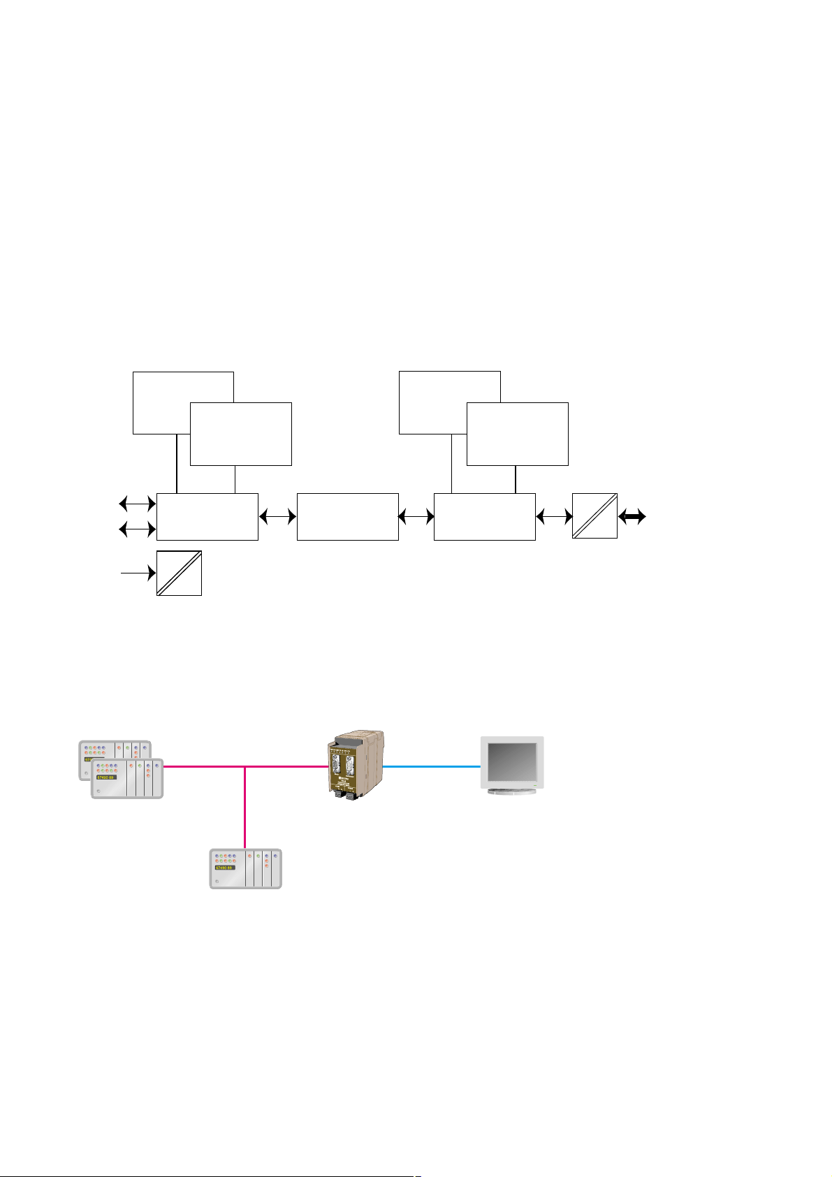
Application examples
Westermo Teleindustri AB • SE-640 40 Stora Sundby,Sweden
Phone +46 16 42 80 00 Fax +46 16 42 80 01
E-mail:info@westermo.se
W estermo W eb site: www.westermo .com
Westermo Teleindustri AB have distributors in several
countries, contact us for further information.
Westermo Data Communications Ltd
Unit 14 Talisman Business Centre • Duncan Road
Park Gate, Southampton • SO31 7GA
Phone:+44(0)1489 580 585 • Fax.:+44(0)1489 580586
E-Mail:sales@westermo.co.uk
Westermo Data Communications GmbH
Goethestraße 67,68753 Waghäusel
Tel.: +49(0)7254-95400-0 • Fax.:+49(0)7254-95400-9
E-Mail:info@westermo.de
Westermo Data Communications S.A.R.L.
9 Chemin de Chilly 91160 CHAMPLAN
Tél :+33 1 69 10 21 00 • Fax :+33 1 69 10 21 01
E-mail :infos@westermo.fr
Subsidiaries
PROFIBUS DP
master
PROFIBUS DP
Operator terminal
FD-40 B
RS-232/485RS-232/485RS-232/485
RS-232/485
Text display
FD-40 B
Messuring device
FD-40 B
Barcode scanner
FD-40 B
1
23
4
56
7
89
A
0B
 Loading...