

Page 1
Fieldbus adapter,
PROFIBUS DP Master
INSTALLATION MANUAL
6630-2220
www.westermo.com
FD-20
©
Westermo Teleindustri AB • 2004 • REV. C
Page 2

2 6630-2220
Contents
1. Safety .................................................................................................................................................................................. 3
2. Approvals ....................................................................................................................................................................... 3
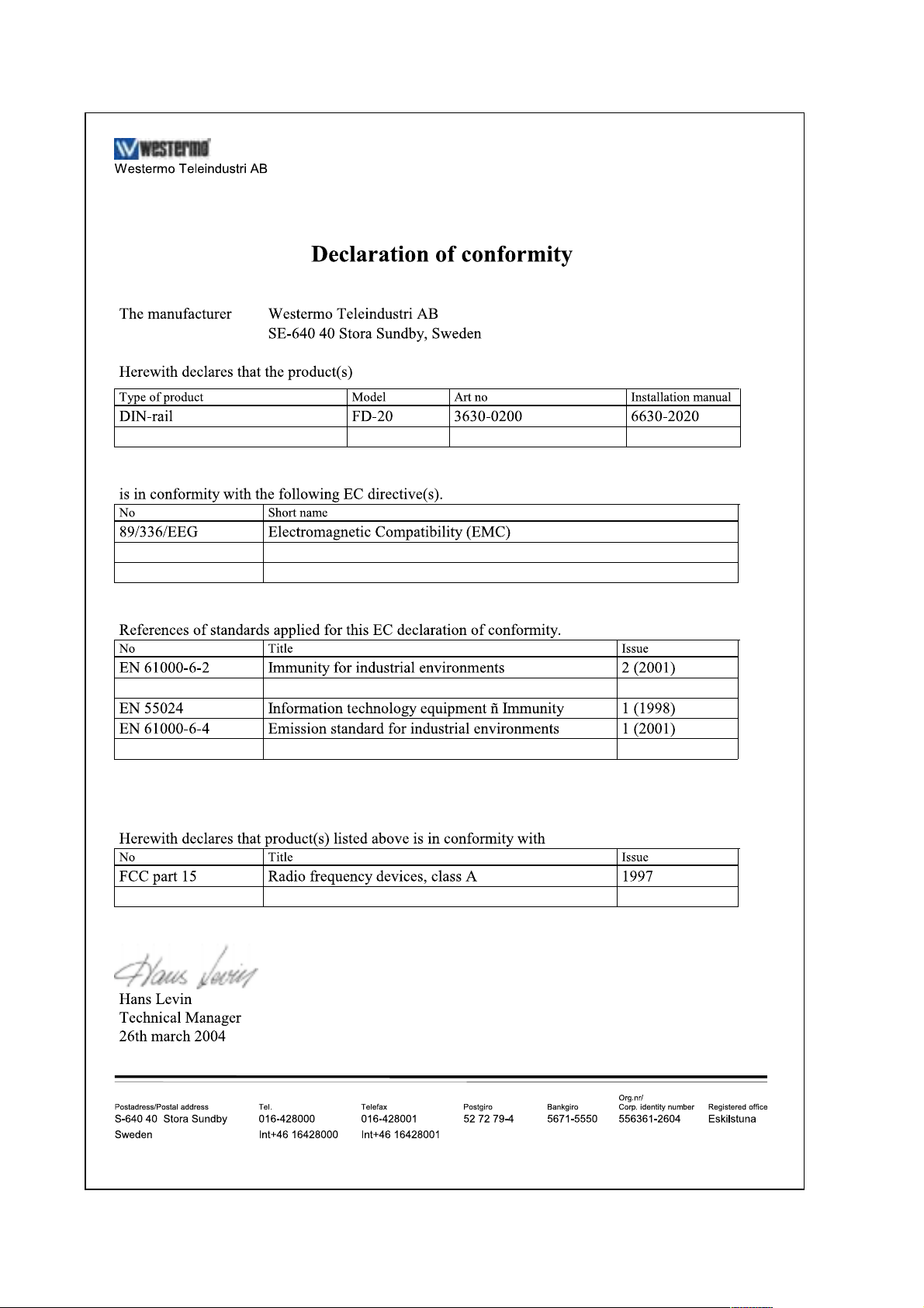
2.1 Declaration of Conformity .......................................................................................................................... 4
3. Introduction ............................................................................................................................................................... 5
3.1 Field of application ....................................................................................................................................... 5–6
4. Specifications ..................................................................................................................................................... 7–8
5. Maintenance .............................................................................................................................................................. 8
6. Installation .......................................................................................................................................................... 9–26
6.1 Mounting/Removal ............................................................................................................................................. 9
6.2 Connections ......................................................................................................................................................... 10
6.2.1 Power ............................................................................................................................................................. 11
6.2.2 PROFIBUS DP ........................................................................................................................................ 11
6.2.3 RS-232 (DTE) ........................................................................................................................................... 11
6.2.4 RS-485 ........................................................................................................................................................... 11
6.3 Indicators ................................................................................................................................................................ 12
6.3.1 LEDindicators .......................................................................................................................................... 12
6.4 Configuration ...................................................................................................................................................... 13
6.4.1 DIP switch settings ..................................................................................................................... 13–15
6.4.2 On-line configuration using SyCon®,
a universal System Configurator
................................................................................................ 16
6.4.2.1 Initiate PROFIBUS DP Master Configuration ................................................... 16
6.4.2.1.1 The first run (no saved project),
Initiate communication
............................................................................................ 16
6.4.2.2 PROFIBUS DP Master configuration using SyCon
®
...................................... 17
6.4.2.2.1 Create a new configuration ................................................................................... 17
6.4.2.2.2 Open an existing project ......................................................................................... 17
6.4.2.2.3 GSD file ................................................................................................................................. 18
6.4.2.2.4 Insert PROFIBUS DP Master .............................................................................. 18
6.4.2.2.5 PROFIBUS DP Master configuration ............................................................ 19
6.4.2.2.6 Insert PROFIBUS DP Slave ................................................................................... 19
6.4.2.2.7 PROFIBUS DP Slave configuration ....................................................... 20–22
6.4.2.3 Load the configuration to the FD-20 ........................................................................ 22
6.4.2.4 Store configuration ................................................................................................................ 23
6.4.2.5 Diagnostics functions ............................................................................................................. 23
6.4.2.5.1 Live list, all devices ....................................................................................................... 23
6.4.2.5.2 Debug mode, PROFIBUS DP and Slave diagnostic ............................ 24
6.4.2.5.3 Global State Field ................................................................................................ 25–26
7. Functional description .................................................................................................................... 27–30
7.1 Halt state ................................................................................................................................................................ 28
7.2 Run state ................................................................................................................................................................. 28
7.3 LED error indication ............................................................................................................................ 29–30
Page 3

36630-2220
1. Safety
General:
Before using this unit, read this manual completely and gather all information on
the unit. Make sure that you understand it fully. Check that your application does
not exceed the safe operating specifications for this unit.
Before installation, maintenance or modification work:
Prevent damage to internal electronics from electrostatic discharges (ESD)
by discharging your body to a grounding point (e.g. use of wrist strap).
Prevent access to hazardous voltages by disconnecting the unit from AC/DC
mains supply and all other electrical connections.
Installation:
This unit should only be installed by qualified personnel.
This unit should only be installed in a “restricted access area”, for example
a lockable cabinet where access is restricted to service personnel only.
This unit is intended for permanent connection to the AC/DC mains supply.
The power supply wiring must be sufficiently fused, and if necessary it must be
possible to disconnect manually from the AC/DC mains supply. Ensure compliance
to national installation regulations.
Units with the rated voltage exceeding 42.4 V peak or 60 VDC, are defined as
class I equipment with a protective earthing conductor terminal.
Units with the rated voltage up to 42.4 V peak or 60 VDC, are defined as class III
equipment and shall be separated from hazardous voltage by double or reinforced
insulation.
This unit uses convection cooling.To avoid obstructing the air flow around the
unit, follow the spacing recommendations (see Installation section).
2. Approvals
Conformity with the Directive 89/336/EEC Electromagnetic Compatibility (EMC)
has been assessed by application of standards EN 61000-6-2 (industrial immunity) and
EN 61000-6-4 (industrial emission).
Meets EN 50170, Profibus-DP Specification.
FCC Part 15 Notice: This equipment has been tested and found to comply with the limits for a Class A digital device,
pursuant to Part 15 of the FCC Rules.These limits are designed to provide reasonable protection
against harmful interference when the equipment is operated in a commercial environment.
This equipment generates, uses, and can radiate radio frequency energy and, if not installed and
used in accordance with this installation manual, may cause harmful interference to radio
communications. Operation of this equipment in a residential area is likely to cause harmful
interference in which case the user will be required to correct the interference at his own
expense.
!
!
!
Page 4
4 6630-2220
2.1 Declaration of Conformity
Page 5
56630-2220
3. Introduction
The FD-20 is designed to provide a method of transferring PROFIBUS I/O data over
serial data links.
The FD-20 contains a PROFIBUS master that can control a network of PROFIBUS DP
Slaves connected to its fieldbus port.The unit can be easily configured within the limits set
by the serial data rate to transfer input and output data between PROFIBUS networks.
The unit is able to transfer PROFIBUS DP data over leased line, dial up modems,
Ethernet or radio systems.
The FD-20 can be used in conjunction with the FD-10
(which contains a PROFIBUS DP Slave)
All Westermo Fieldbus Adapters use the same protocol to communicate with each other
via the serial interface.
3.1 Field of application
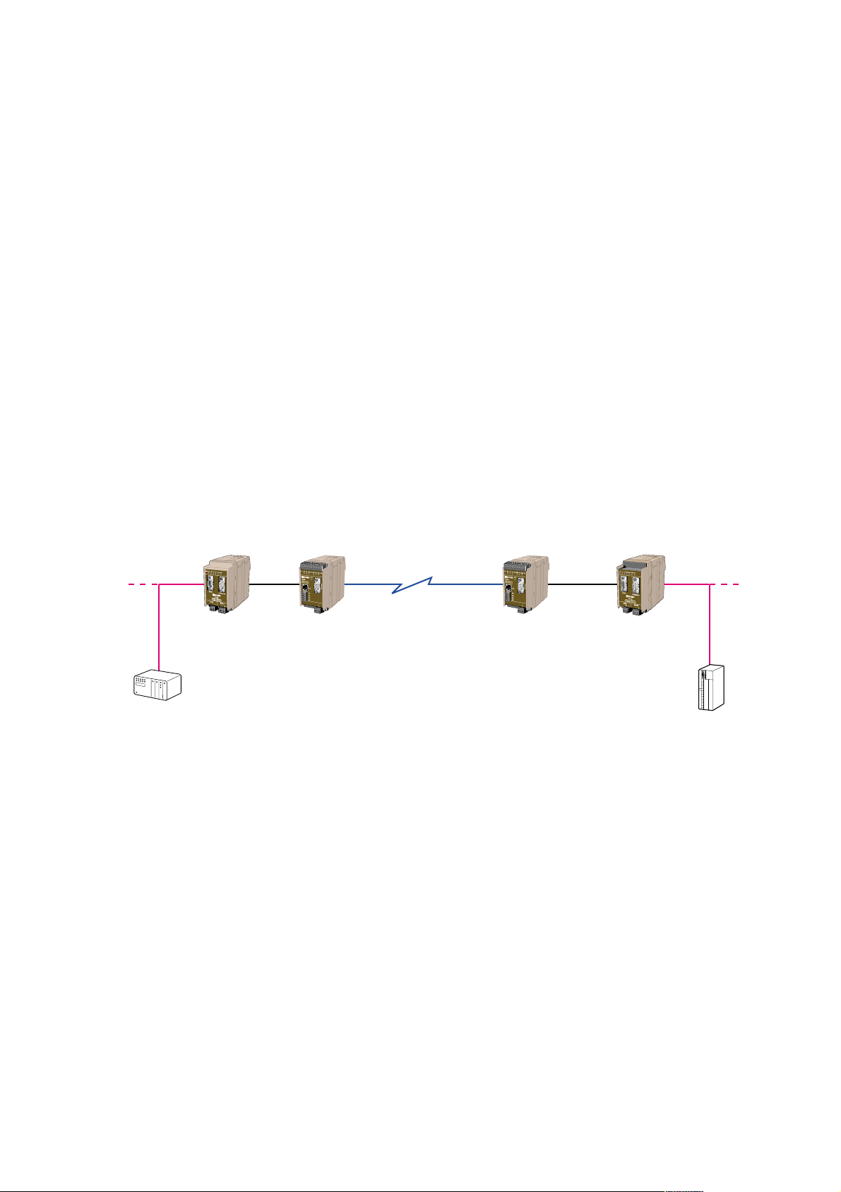
Point to point transfer
The continuous transfer of defined PROFIBUS I/O data between one FD-10 P
(Fieldbus adapter PROFIBUS DP Slave) and one FD-20
(Fieldbus adapter PROFIBUS DP Master).
*PSTN= Public Switch Telephone Network
FD-10 P
PROFIBUS DP
PROFIBUS DP
FD-20
PROFIBUS DP Master
Modem
(e.g PSTN*, Radio)
PROFIBUS DP Master
PROFIBUS DP Slave
Modem
(e.g PSTN*, Radio)
Page 6
6 6630-2220
Point to point over Ethernet
The continuous transfer of defined PROFIBUS I/O data over Ethernet, between one
FD-10 P (fieldbus adapter PROFIBUS DP Slave) and one FD-20 (Fieldbus adapter
PROFIBUS DP Master).
This application is created by using one FD-10 P (point to point mode) and one
ED-10 UDP (Ethernet adapter) in the main PROIBUS DP network and one ED-10 UDP
and one FD-20 in the remote network.The FD-20 can support a number of
PROFIBUS DP Slaves
FD-10 P
PROFIBUS DP
PROFIBUS DP
FD-20
PROFIBUS DP Master
ED-10 UDP
Ethernet
PROFIBUS DP Master
PROFIBUS DP Slave
ED-10 UDP
Configure ED-10:
Data rate the same as
FD-10 serial port.
Local IP : i.e:10.0.0.11
Remote IP: i.e: 10.0.0.12
Configure ED-10:
Data rate the same as
FD-20 serial.port
Local IP: i.e:10.0.0.12
Remote IP: i.e: 10.0.0.11
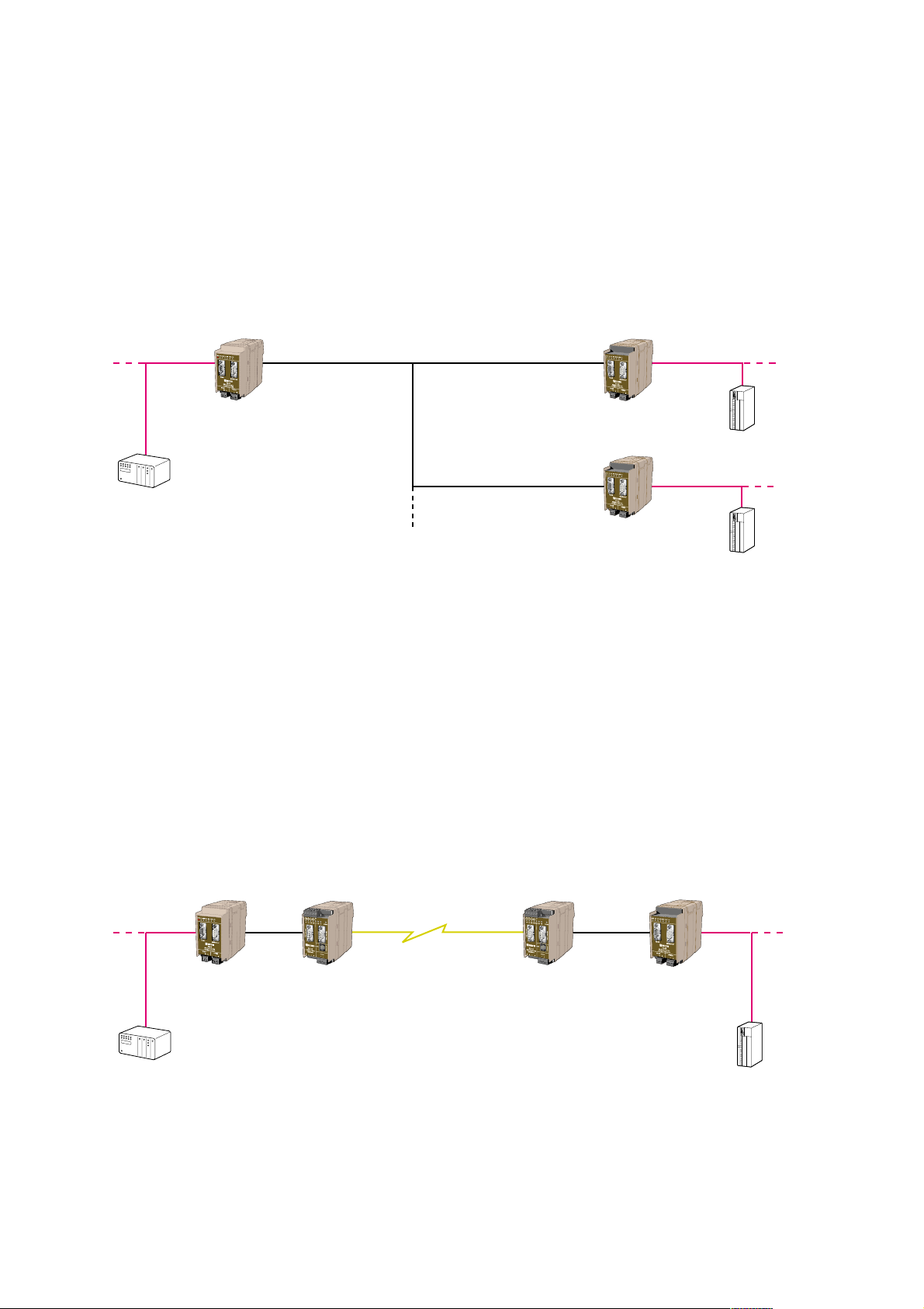
Master controlled transfer (Addressed)
The transfer of defined PROFIBUS I/O data between one FD-10 A controlled by a
PROFIBUS DP Master and several FD-20s.The FD-10 acts as serial transfer master
and can transfer I/O data between various addressed FD-20s.This solution is ideal
when a PROFIBUS DP Master needs to connect to two, or more, independent remote
PROFIBUS DP Slaves.A radio system, multi-drop modem or RS-485 bus is typically used
as the connecting medium.The serial data rate is independent of the PROFIBUS DP rate,
so each PROFIBUS DP network could run at different data rates to the serial backbone.
FD-10 A
PROFIBUS DP Slave
PROFIBUS DP Slave
PROFIBUS DP Master
Serial
master
Serial
slave
Serial
slave
PROFIBUS DP
PROFIBUS DP
PROFIBUS DP
FD-20
PROFIBUS DP Master
FD-20
PROFIBUS DP Master
Page 7

76630-2220
4. Specifications
FD-20
Rated voltage 12 to 48 VDC
Operating voltage 9.6 to 57.6 VDC
Rated current 250 mA @ 12 VDC
120 mA @ 24 VDC
65 mA @ 48 VDC
Rated frequency DC
Polarity Reverse polarity protected
Connection Detachable screw terminal
Connector size 0.2 – 2.5 mm2(AWG 24-12)
Fuse To be externally fused
Power
PROFIBUS DP interface
Electrical specification RS-485 / EN 50 170
Data rate 9 600 bit/s, 19.2, 93.75, 187.5, 500, 1 500, 3 000, 6 000 and
12 000 kbit/s
Connection D-sub (female)
Circuit type TNV-1
Termination External
RS-485 interface
Electrical specification RS-485
Data rate 1 200, 2 400, 4 800, 9 600 bit/s, 14.4, 19.2, 38.4, 57.6
and 115.2 kbit/s
Connection Detachable screw terminal
Connector size 0.2 – 2.5 mm
2
(AWG 24-12)
Circuit type TNV-1
RS-232 interface
Electrical specification RS-232
Data rate 1 200, 2 400, 4 800, 9 600 bit/s, 14.4, 19.2, 38.4, 57.6
och 115.2 kbit/s
Connection D-sub, DTE
Circuit type SELV
Page 8

8 6630-2220
Environmental
Temperature, operating –25 to 70°C
Temperature, storage
and transportation –25 to 70°C
Relative humidity, operating 5 to 95 % (non-condensing)
Relative humidity, storage
and transportation 5 to 95 % (condensation allowed outside packaging)
Mechanical
Dimension (W x H x D) 55 x 100 x 132 mm (including connectors)
55 x 100 x 128 mm (enclosure)
Weight 0.3 kg
Mounting 35 mm DIN-rail
Degree of protection IP 20 (IEC 529)
Isolation between interfaces
Power to all other 1.0 kV RMS @ 50 Hz and 60 s duration
PROFIBUS DP to all other 1.0 kV RMS @ 50 Hz and 60 s duration
Internal
electronics
Power
PROFIBUS DP
RS-485
RS-232
Only one of RS-232 or
RS-485 can be connected
simultaneoysly
5. Maintenance
No maintenance is required, as long as the unit is used as intended within the specified
conditions.
Page 9
96630-2220
6, Installation
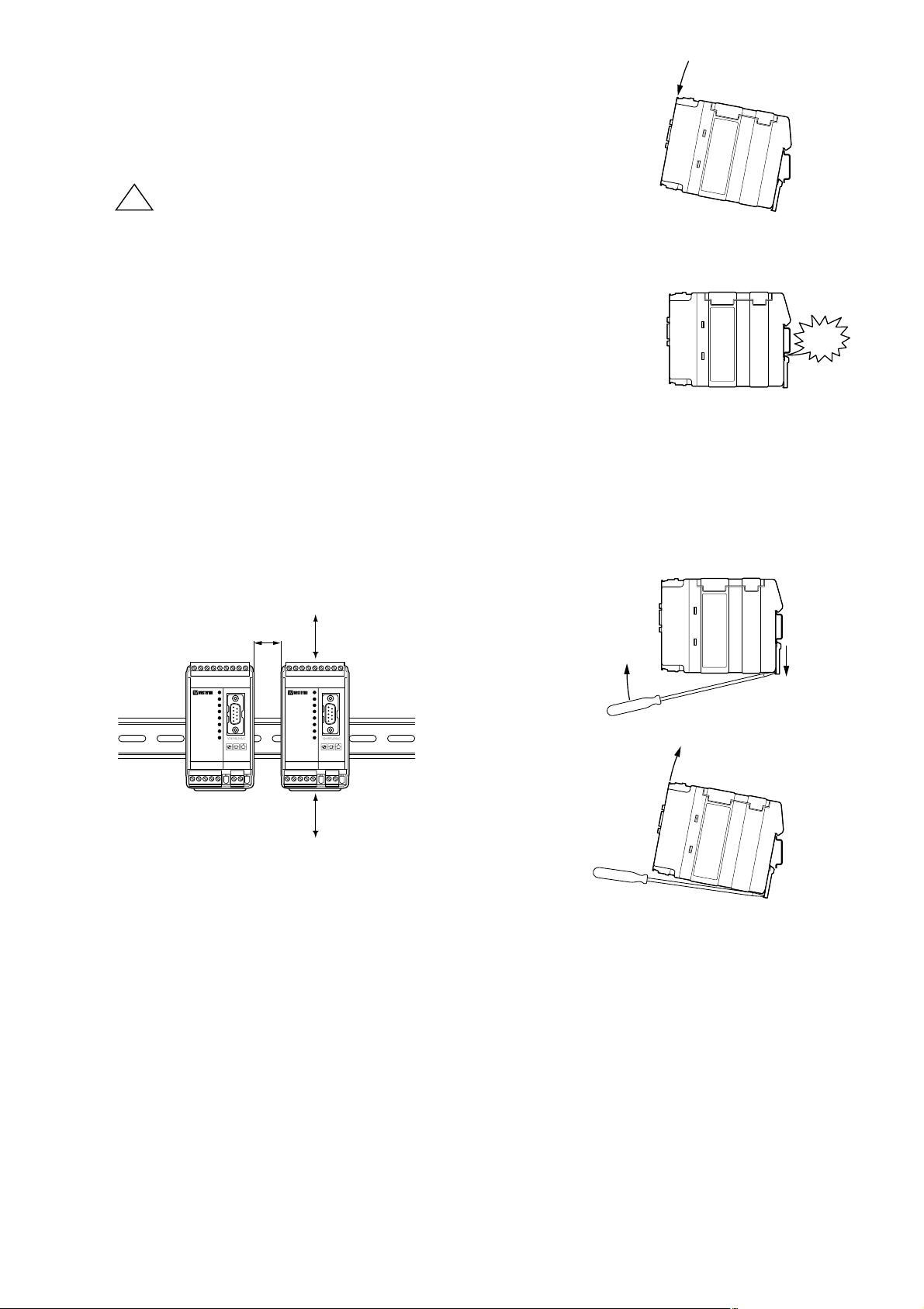
6.1 Mounting / Removal
Before mounting or removing the unit:
Prevent damage to internal electronics from electrostatic
discharges (ESD) by discharging your body to a grounding
point (e.g. use of wrist strap).
Prevent access to hazardous voltages by disconnecting the
unit from AC/DC mains supply and all other electrical
connections.
Mounting
This unit should be mounted on 35 mm DIN-rail which is horizontally mounted on a wall
or cabinet backplate.
This unit uses convection cooling.To avoid obstructing the airflow around the unit,
use the following spacing rules. Recommended spacing 25 mm (1.0 inch) above/below
and 10 mm (0.4 inches) left/right the unit.
Snap on mounting, see figure
Removal
Press down the black support at the back of the unit
using a screwdriver, see figure.
10 mm *
(0.4 inches)
25 mm
25 mm
* Spacing (left/right) recommended
for full operating temperature range
!
C
I
L
C
!
K
Page 10
10 6630-2220
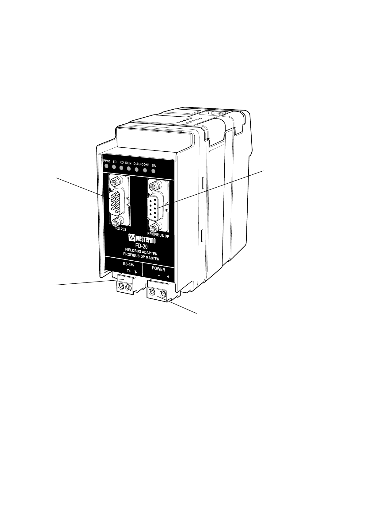
6.2 Connections
PROFIBUS DP
Power
RS-232
RS-485
Page 11

116630-2220
6.2.1 Power
2-pos screw terminal Direction Description
No. 1 In 0 VDC (–)
No. 2 In +12 to +48 VDC (+)
6.2.4 RS-485
2-pos Detachable screw terminal Direction Description
No. 1 In/Out Transmit/Receive T/R+ (T+)
No. 2 In/Out Transmit/Receive T/R– (T–)
6.2.2 PROFIBUS DP
9-pos D-sub Direction Description
No. 1 – –
No. 3 – –
No. 3 In/Out RxD/TxD-P
No. 4 Out CNTR-P
No. 5 – DGND
No. 6 Out VP
No. 7 – –
No. 8 In/Out RxD/TxD-N
No. 9 – DGND
6.2.3 RS-232 (DTE)
9-pos D-sub Direction Description
No. 1 – –
No. 2 In Receive Data (RD)
No. 3 Out Transmit Data (TD)
No. 4 Out Data Terminal Ready (DTR)
No. 5 – Signal ground (SG)
No. 6 – –
No. 7 Out Request To Send (RTS)
No. 8 In Clear To Send (CTS)
No. 9 – –
1
2
1
2
5
4
3
2
1
9
8
7
6
1
2
3
4
5
6
7
8
9
Female
Male
Page 12

12 6630-2220
6.3 Indicators
6.3.1 LED indicators
PWR On In service (power)
Off Out of service
TD On Transmit serial (RS-232/485) data
Off –
RD On Receive serial (RS-232/485) data
Off –
RUN On Running, PROFIBUS DP and serial (RS-232/485)
transfer in operation. Exchanging data with all slaves.
Flashing (2 Hz) PROFIBUS DP error,
e.g. missed data exchange with a slave
Off –
DIAG On Stat_Diag (static diagnostics) set
Off –
CONF On Configuration mode
Flashing (2 Hz) Missed or invalid configuration
Flashing (once) The received serial (RS-232/485) data length ≠
slaves output data length (as defined by configuration)
Off –
BA On PROFIBUS DP in operation
Flashing (2 Hz) Failed PROFIBUS DP master initiation
Off –
Page 13

136630-2220
6.4 Configuration
Configuration is divided into two parts:
… Serial transfer configuration, by DIP-switch settings in the FD-20.
… PROFIBUS DP Master configuration, using SyCon
®
a PC based universal system
configurator
6.4.1 DIP switch settings
DIP-switches are accessable under the lid on top of the unit. DIP-switches are
used to configure the unit.
Warning!
Prevent damage to internal electronics from electrostatic discharges (ESD) by
discharging your body to a grounding point (e.g. use of wrist strap), before the
lid on top of the unit is removed.
Warning! Do not open connected equipment.
Prevent access to hazardous voltages by disconnecting the unit from AC/DC
mains supply and all other electrical connections.
!
!
Page 14

14 6630-2220
S3:1–8 S2:1–8 S1:1–8
Switch 1
ON
12345678
S1
No termination (RS-485)
ON
12345678
S1
Termination with fail-safe
(RS-485)
ON
12345678
S1
Data control
ON
12345678
S1
RTS/CTS control
ON
12345678
S1
RS-232 as serial
transfer port
ON
12345678
S1
RS-485 as serial
transfer port
ON
12345678
S1
2 ms turning time
Factory setting
ON
12345678
S1
No termination (RS-485)
Data control
RS-232 as serial transfer port
No turning time
5 s timeout allowed between received frames
No serial transfer at Stat_Diag (static diagnostics)
Reset slaves output data at running interrupt (RUN-LED off)
ON
12345678
S2
Default transfer setting
9 600 bit/s, 8 data bits,
no parity, 1 stop bit
ON
12345678
S3
Configuration mode, SyCon
®
* When this switch is selected, the slaves output remain at serial transfer interruption. To ensure that
the slaves output remain even at PROFIBUS DP interruption as well as power supply interruption or
restart of FD-20, select this switch together with selecting Controlled release of communication by the
application program in DP Master settings window (accessible from the Master Configuration window)
during the SyCon
®
configuration.
ON
12345678
S1
100 ms turning time
ON
12345678
S1
Timeout, 5 s allowed
between received frames
ON
12345678
S1
Timeout, 40 s allowed
between received frames
ON
12345678
S1
No serial transfer at
Stat_Diag (static diagnostics)
ON
12345678
S1
Serial transfer even
at Stat_Diag
(static diagnostics)
ON
12345678
S1
Stop the data exchange
with slaves at serial
transfer timeout
ON
12345678
S1
Continue the data exchange
with slaves at serial transfer
timeout*
NOTE
DIP-switch alterations are only
effective after a power on.
Page 15

38.4 kbit/s
156630-2220
Switch 2
ON
12345678
S2
9 600 bit/s, 8 data bits,
no parity, 1 stop bit
ON
12345678
S2
1 200 bit/s
ON
12345678
S2
2 400 bit/s
ON
12345678
S2
4 800 bit/s
ON
12345678
S2
9 600 bit/s
ON
12345678
S2
14.4 kbit/s
ON
12345678
S2
19.2 kbit/s
ON
12345678
S2
57.6 kbit/s
ON
12345678
S2
115.2 kbit/s
Switch 3
ON
12345678
S3
Serial transfer mode,
point to point
ON
12345678
S3
Configuration mode,
SyCon
®
ON
12345678
S3
Serial transfer mode,
addressed with address range
1–254
(binary 1000 0000 – 0111 1111)
E.G.
Addr. 1 = 1000 0000
Addr. 254 = 0111 1111)
ON
12345678
S2
8 data bits, No parity
ON
12345678
S2
8 data bits, Even parity
ON
12345678
S2
8 data bits, Odd parity
ON
12345678
S2
1 stop bit
ON
12345678
S2
2 stop bits
S2:7 används ej
ON
12345678
S2
Page 16

16 6630-2220
6.4.2 On-line configuration using SyCon®, a universal System
Configurator
This part of the installation guide describes the usage of the SyCon®(universal SYstem
CONfigurator) software to perform an on-line configuration of the PROFIBUS DP
Master within the FD-20. For software installation details and general SyCon
®
operation,
please see the “SyCon
®
Installation manual” on the CD, supplied with the FD-20.
Required items
… PC with installed System Configurator SyCon
®
.
… FD-20 with power supply.
… DTE-DTE RS-232 serial cable (crossover/null modem cable).
… PROFIBUS DP network with connected slaves.
Not necessary, but makes correct configuration easier.
6.4.2.1 Initiate PROFIBUS DP Master Configuration
… Set the FD-20 to configuration mode by setting DIP-switch S1 to S3 to factory default
setting (all positions on S1 and S2 to off and all positions on S3 to on).
… Connect a DTE-DTE RS-232 serial cable (crossover/null modem) to the serial port of
the PC and RS-232 port of the FD-20.
… Power on the FD-20 and wait for the CONF LED to activate.
… Start SyCon
®
on the PC.
6.4.2.1.1 The first run (no saved project), Initiate communication
… Initiate communication with the FD-20 by selecting Online > Start communica-
tion and assign the Communication Interface (CIF) Serial Driver. This serial driver is
used by the FD-20.
Figure 1: CIF driver selection
Page 17

176630-2220
… Press Connect COM X to establish a connection (X is the PC serial port).
The system configurator sends a request to the corresponding COM port
interface and polls the firmware of the FD-20. Name,Type etc. will indicate
when a device is connected. Select the COM port tick box and press OK.
6.4.2.2 PROFIBUS DP Master configuration using SyCon
®
Below we have described the most essential parts of a FD-20 Master configuration. For
more details, use the SyCon
®
help facilities by selecting Help > Help Topics....
6.4.2.2.1 Create a new configuration
Select File > New, choose PROFIBUS and press OK.The PROFIBUS configuration
window will open after about 10s, a vertical line to the left of the window.
… The name of your configuration file can be assigned now or when the configuration is
completed by selecting File > Save as, choose a project name and store under the
folder Project.
6.4.2.2.2 Open an existing project
Select File > Open, choose project (*.pb) and press Open.
Figure 3: Fieldbus selection
Figure 2: CIF serial driver assignment
Note: The ”Connect COM X” will not be activ if a projekt window allready are open.
Page 18

18 6630-2220
6.4.2.2.3 GSD file
When SyCon®is started, the System Configurator automatically loads all the GSD files
stored in the GSD directory.The device names are placed into an internal list. During
configuration, device-specific data is loaded directly from the GSD files.
If a DP Slave device does not appear in the selection list, then a corresponding GSD file
must be copied into the GSD directory by:
… Select File > Copy GSD, or
… Copy the GSD file into the SyCon
®
GSD directory with Internet Windows Explorer
and then retrieve the GSD files into the GSD directory with Settings > Path
and OK
6.4.2.2.4 Insert PROFIBUS DP Master
… Click on the symbol in figure 5 or choose the Insert > Master menu and the insert
master pointer will be displayed, a left arrow and letter M.
Click on the position where the Master is to be inserted.The dialog box, from which a
master can be chosen, then opens.
Select CIF30-DPM / CIF104-DPM /-R as the master for the FD-20, by clicking on it in
the list of available masters and then click the Add button to put this master in the
selected masters list. Press OK to confirm the selection.
Figure 4: GSD files and bitmaps location
Figure 5:The insert master button
Figure 6: Master selection dialog box
The insert master pointer
Page 19

196630-2220
6.4.2.2.6 Insert PROFIBUS DP Slave
… Click on the symbol or choose the Insert > Slave menu to get the Insert slave
pointer, a left arrow and letter S.
… Click on the position where the slave is to be inserted.The dialog box, from which
one or more slaves can be selected, will open.
… Select a Slave by clicking on it in the list Available slaves and then click the Add>>
button to put this slave into the Selected slaves list. Several different slaves can be
selected, as well as the same slave several times. Once you have selected the required
slaves press OK.
6.4.2.2.5 PROFIBUS DP Master configuration
Double click on the master symbol or set the focus on to the master (left mouse click)
and then select Settings > Master Configuration, to open the master configuration
window. The description and the station address can be set in this window.
Set the Auto addressing check box. Note: automatic addressing is recommended for
the DP Master.The addresses are allocated from 0 and incremented in accordance with
the entry sequence of the Slaves before downloading and can be viewed and checked in
the View > Address Table. Click OK
Figure 7: Master configuration
Figure 8:The insert slave button The insert slave pointer
Page 20

20 6630-2220
The Available slaves list on the left displays all the slave devices whose GSD files have
been loaded into the GSD directory.A filter can be used to limit the selection list to
slave type and vendor (manufacturer).The slave can be added to the right-hand list with a
double mouse click or with the Add button. All devices in the right-hand list are assigned
to the master shown in the window above the list. If the slaves are selected individually,
then each slave can be allocated a Station address as well as a name in the Description
field. For every slave entered in the right-hand list, the station address count is automatically incremented by one but can be overwritten by the user in the Station address field.
6.4.2.2.7 PROFIBUS DP Slave configuration
Double click the PROFIBUS DP slave device symbol or click the symbol with the left
mouse button and then choose the Settings > Slave Configuration, to open the
slave configuration window.The slave-specific configuration is carried out in this window.
Here, the modules and their addresses are allocated into the process data memory
of the master.
Note 1: The offset addresses refer to the addressing of the data in the Master!
The address information does not refer to the addressing of the data in
the Slave! The Slave organises its own data addressing.
The selection list (upper list) shows all the possible slave modules. In the case of a simple
slave, one module is shown and this is automatically copied into the configuration list
(lower list). In the case of a modular slave, the user must select the required modules and
transfer these by means of a double click or transfer it using the Append Module
button into the configuration list (lower list).
For configuration of slave modules (selection of modules), proceed as follows:
… Transfer all the required modules from the selection list (upper list) into the
configuration list (lower list) by a double click or using the Append Module button.
Click on OK when configuration of this slave is complete.
Figure 9: Insert slave
Page 21

216630-2220
Note 2: The sequence of the modules in the configuration list (lower list) is important
and must be identical to the actual slave.Typically, the sequence follows the
actual physical sequence. There are slaves to which this rule does not apply.
For instance analogue modules must be entered before digital modules.
Note 3: The DP slaves utilize the Watchdog Control setting in order to detect
communication errors to the assigned DP Master.When the DP slave detects
a break in an established connection, defined by a watchdog timeout, the slave
carries out an independent reset and puts all the outputs into a secure condition.
Caution:When the Watchdog Control has been deactivated, it is possible
that the outputs are not securely reset by the slave if the connection is lost.
Note 4: Activate Device in actual configuration must be selected. If not, no data
exchange will occur from the bus to this slave.
Figure 10: Slave configuration
Page 22

22 6630-2220
PROFIBUS DP data rate
PROFIBUS DP data rate can be set in the Settings > Bus Parameters menu.
… After a successful configuration the FD-20 must be powered off and the DIP-switches
set to the desired operational mode, before it is powered on again.
Note 1: Before the download is carried out, the configuration is tested by the
Configurator.The most common cause of error is overlapping of addresses in
the process data image.This will not occur if addresses in the process data
image are assigned automatically, by having the Auto addressing button
checked in the Master Configuration window.
Note 2: The configuration is transferred into the FD-20s PROFIBUS DP Master and
stored in non-volatile memory (FLASH).
Note 3: After the download, the master carries out an internal restart and starts the
communications providing the Automatic Release of Communication by
the Device setting has been made in the DP Master Settings.
6.4.2.3 Load the configuration to the FD-20
… When master and slaves has been inserted, click on the master symbol with the left
mouse.
… In order to release the configuration and network access, a transfer (Load) to the
FD-20 must be carried out on the Online > Download menu.A warning will appear
that communications on the PROFIBUS will be interrupted.This warning must be con-
firmed.
Note: If “Driver select” menu pops up, see “The first initiation (no saved project),
Initiate communication” section.
Figure 11: PROFIBUS DP data rate setting
Figure 12: Configuration download to FD-20
Page 23

236630-2220
6.4.2.4 Store configuration
… A configuration file can be assigned now or when the configuration is complete by
selecting File > Save as, choose a project name and store in the Project folder.
… If this configuration has not previous been saved with the project file, the File > Save
As menu must be used to store the configuration, else the File > Save menu can be
used.
6.4.2.5 Diagnostics functions
The most important diagnostic functions are described below, for further diagnostic
information use the Help > Help Topics.. menu.
Note: The FD-20 must be in configuration mode to get access to the diagnostics
functions. See “Initiate PROFIBUS DP Master Configuration” section.
6.4.2.5.1 Live list, all devices
Click on the master symbol with the left mouse button.Then select the Online > Live
List menu and obtain an overview of all active devices on the PROFIBUS network.
Figure 13: Live list
A green highlighted number shows a master and blue number a slave, where the number
indicates the station address.The meaning of the other colours is given in the list above
the table.
Page 24

24 6630-2220
6.4.2.5.2 Debug mode, PROFIBUS DP and Slave diagnostic
Click on the master symbol with the left mouse button.Then select the Online > Start
Debug Mode menu.After starting the debugger SyCon
®
cyclically interrogates the status of the PROFIBUS DP network and the individual conditions of the attached devices. If
there is an error on a device the bus line to this slave is drawn in red otherwise the line
will be is green.
To end Debug Mode select the menu Online > Stop Debug Mode.
If diagnostic information is available for a specific device while running debug mode, the
text Diag appears in red next to the device icon.To get further device specific diagnostic
information then double click on the device itself or set the focus on the device and
select Online > Device Diagnostic.
To check that the I/O modules are correctly configured, click on Compare
Configuration.The SyCon
®
configuration and the actual configuration (I/O modules)
must be identical.
To get detailed information about the slave diagnostics, see Help > Help Topics..
and search for “PROFIBUS DP Device Diagnostics” under the index.
Figure 14: Debug mode
Figure 15: Slave diagnostic
Page 25

256630-2220
6.4.2.5.3 Global State Field
Click on the master symbol with the left mouse button.Then select the Online >
Global State Field menu. A display window opens in which the cyclic statuses of the
bus condition and the connected devices are shown.
Figure 16: Global state
The first row shows the main state of the master.This can have the condition
OPERATE or STOP. The next row shows individual bus errors.A current error
is shown in a red field.The meanings of the individual abbreviations are shown below.
TOUT Timeout error, the device has detected an expired supervision timeout caused
by rejected PROFIBUS telegrams.
NRDY Host not ready notification, indicates if the host program has set its state to
operative or not. If this bit is set the host program is not ready to communicate.
EVE Event error, the device has detected bus short circuits.The number of detected
events is stored in the bus statistic information variable.The bit will be set when
the first event is detected and will not be cleared.
FAT Fatal error, because of a serious bus error, no further bus communication is
possible.
NEXC Non exchange error, at least one slave has not reached the data exchange state
and no process data can be exchanged.
Page 26

26 6630-2220
ACLR Auto clear error, the device stopped communication to all slaves and reached
the auto-clear end state.
CTRL Control error, parameterisation error.
The device specific status bits, Parameterised Devices,Activated Devices and
Devices with Diagnostic are shown if you click on the respective buttons.
The activated addresses are shown as coloured numbers.This application updates
online the status in the global state field.You can see the diagnostics by double clicking
on a highlighted device station address.
Page 27

PROFIBUS DP
GSD-file HIL_7505.GSD
Device type DP Master (Class 1)
Address range 0 to 125 (Default address=0)
Serial transfer
Transfer type Point to point Addressed
Seriell adress – 1 to 254
Transfer initiation Passive. FD-20 reply after a correct received frame
Transfer check 16 bit CRC
Allowed timeout between Up to 5 or 40 s, set by DIP-switch (S1:6)
correct received frames
Allowed timeout between Up to 100 ms
correct received frames
Turning time 2 or 100 ms, set by DIP-switch (S1:5)
Serial transfer of PROFIBUS DP data
Number of modules Unlimited (depend on remote Fieldbus adapter)
Length of input data Up to 249 bytes
Length of output data Up to 249 bytes
Data location Slaves: In increased address order
Modules: In order as defined by configuration tool
Running, PROFIBUS DP • Correct received frame with correct data length, and
and serial (RS-232/485) • All slaves exchanging PROFIBUS DP data, and
transfer in operation, if: • No Stat_Diag (static diagnostics), or
• Ignored Stat_Diag (static diagnostics), set by DIP-switch
(S1:7)
Serial transfer timeout • Stop the data exchange with slaves
(SW 1:8 set to OFF), or
• Continue the data exchange with slaves
(SW 1:8 set to ON)
276630-2220
7. Functional description
The FD-20 acts as a stand-alone master that can control all PROFIBUS DP traffic with
connected slaves on that bus.The master can be configured, within the limits set by the
serial transfer of the input and output data.The serial link has higher priority than the
PROFIBUS DP network.
If the stop PROFIBUS data exchange on serial transfer timeout (SW 1:8 set to OFF) is
selected, PROFIBUS communication with the slaves is stopped.This eliminates the risk of
a slaves output being lost whilst the link is down.
Alternatively the PROFIBUS DP network can be run whether the serial link is operational or not, by selecting the continue data exchange with slaves at serial transfer timeout (SW 1:8 set to ON).The PROFIBUS DP traffic will be active as long as no failure
occurs on the PROFIBUS DP network.
Page 28

28 6630-2220
To ensure that the slaves output remain even at PROFIBUS DP interruption as well as
power supply interruption or restart of FD-20, select the continue data exchange with
slaves at serial transfer timeout (SW1:8) together with selecting “Controlled release of
communication by the application program” in DP Master settings window (accessible
from Master Configuration window), during the SyCon
®
configuration
A fully operational PROFIBUS DP network communicating with all slaves (not necessarily
exchanging data) is indicated by an active BA LED. Stat_Diag (static diagnostics) will be
indicated by an active DIAG LED.
As long as the FD-20 is in a run state, the data from the PROFIBUS DP slaves will be
exchanged with a remote fieldbus adapter via the serial transfer line.
Received serial data frames are indicated by the RD LED, even if there are errors.
Transmitted serial data frames are indicated by the TD LED.Transmission will occur after
receiving a correct frame and if the BA and RUN LED are active and the DIAG LED is
inactive, or if Stat_Diag (static diagnostics) is ignored.
7.1 Halt state
The FD-20 is in a halt state if the serial connection with the remote fieldbus adapter has
not been established.The RUN LED will be inactive.
The FD-20 will wait to receive a correct serial frame from a remote fieldbus adapter.
The FD-20 goes into a run state if a correct frame is received and the received data
length complies with the output data length (defined by configuration) and when the FD20 is exchanging data with all the PROFIBUS DP slaves.
Note: When the FD-20 receives a correct serial frame the PROFIBUS DP network will
be initiated (SW 1:8 set to OFF).The time to start the data exchange with all
slaves will be dependent on the number of slaves, the slave’s complexity and
PROFIBUS DP data rate. If the start time is so long that a new serial frame is
received, this new frame must be correctly received before the FD-20 goes to a
run state. Only the last received frame will be replied.
7.2 Run state
The FD-20 is in a run state if the serial connection with another fieldbus adapter has
been established, data is exchanging via the serial line and this data is exchanging with
all connected PROFIBUS DP slaves.The BA and RUN LEDs will be active.
If an error free serial frame is received, a reply will be sent after the turning time. (S1:5)
The FD-20 will go into a halt state if the time exceeds the allowed timeout since the last
correctly received frame (S1:6).
Note: If the allowed timeout between received frames is exceeded, this is indicated by
an inactive RUN LED and if “Stop the data exchange with slaves at serial transfer
timeout” (SW 1:8 set to OFF) is selected, the data exchange with all slaves is
stopped.
Page 29

296630-2220
7.3 LED error indication
PWR
Off
On
On
On
On – –
Flashing
(2 Hz)
–––
On –
On
while
receive
frame
Off – – Off
–––––
Flashing
(2 Hz)
Off
On
while
receive
frame
––
Flash
after a
received
frame
–
––––
Flashing
(2 Hz)
–
––––––
TD RD RUN DIAG CONF BA Error / Action(s)
No power supply or internal
failure / Connect power
supply
Failed PROFIBUS DP
initiation / Return product
to manufacturer
PROFIBUS DP error, such as
a bus short circuit or interrupt of bus or supply to any
slave /
• Check the bus cables,
supply of the slaves etc.
• Set to configuration mode
and use the SyCon
®
diagnostics functions to
find the error
Incorrect data received, or
PROFIBUS DP error /
• Incorrect serial data setting
or address (if addressed
mode)
• Check bus cables, power
supply of slaves etc.
• Set to configuration mode
and use the SyCon
®
diagnostics functions to
find the error
• No stored configuration
• Configuration exceed max
allowed data length /
New Master configuration
by SyCon
®
The received serial data
length ≠slaves output data
length (defined by configuration tool) / Modify remote
fieldbus adapter
configuration, or
Modify FD-20 configuration
Page 30

No slave found at
PROFIBUS DP initiation.
Check bus cables, power
supply of slaves, etc.
30 6630-2220
PWR
On –
On
while
receive
frame
Off – – On
TD RD RUN DIAG CONF BA Error / Action(s)
PROFIBUS DP operating but
incorrect data received /
Incorrect serial data setting
or address
(if addressed mode)
On – – – On – On
Stat_Diag (static diagnostics)
set by any slave / Set to
configuration mode and use
the SyCon
®
diagnostics functions to find slave and diagnostics.
–––
Flashing
(2 Hz)
Flashing
(2 Hz)
Flashing
(2 Hz)
Flashing
(2 Hz)
Page 31

Page 32

T04-0227 • 6630-2220 04.08 Mälartryck AB, Eskilstuna, Sweden
Westermo Teleindustri AB • SE-640 40 Stora Sundby, Sweden
Phone +46 16 42 80 00 Fax +46 16 42 80 01
E-mail: info@westermo.se
Westermo Web site: www.westermo.com
Westermo Teleindustri AB have distributors in several
countries, contact us for further information.
Westermo Data Communications Ltd
Unit 14 Talisman Business Centre • Duncan Road
Park Gate, Southampton • SO31 7GA
Phone: +44(0)1489 580 585 • Fax.:+44(0)1489 580586
E-Mail: sales@westermo.co.uk
Westermo Data Communications GmbH
Goethestraße 67, 68753 Waghäusel
Tel.: +49(0)7254-95400-0 • Fax.:+49(0)7254-95400-9
E-Mail: info@westermo.de
Westermo Data Communications S.A.R.L.
9 Chemin de Chilly 91160 CHAMPLAN
Tél : +33 1 69 10 21 00 • Fax : +33 1 69 10 21 01
E-mail : infos@westermo.fr
Subsidiaries
Application example
PSTN/GSM/Ethernet/leased line/
dedicated line
Serial data
Data rate
up to 115.2 kbit/s
Serial data
Data rate
up to 38.4 kbit/s
FD-20
PROFIBUS DP Master
PROFIBUS DP Slave
PROFIBUS DP Slave
PROFIBUS DP Slave
PROFIBUS DP Slave
PROFIBUS DP Slave
PROFIBUS DP Slave
PROFIBUS DP Master
FD-10
PROFIBUS DP Slave
 Loading...