

Page 1
Fieldbus Adapter
INSTALLATION MANUAL
6630-2212
www.westermo.com
FD-10
©
W estermo T eleindustri AB • 2003 • REV.A
Page 2

2 6630-2212
Contents
1. Safety .................................................................................................................................................................................. 4
2. Approvals ....................................................................................................................................................................... 4
2.1. Declaration of Conformity ..................................................................................................................... 5
3. Introduction ............................................................................................................................................................... 6
3.1 Device types ....................................................................................................................................................... 6
3.2 When are FD-10 devices useful? ........................................................................................................ 6
3.3 Field of application ................................................................................................................................. 7–8
4. Specifications .................................................................................................................................................. 9–10
4.1 Interfaces .............................................................................................................................................................. 9
4.2 Insulation between interfaces ........................................................................................................... 10
4.3 Climatic environment ............................................................................................................................. 10
4.4 Mechanics ......................................................................................................................................................... 10
5. Maintenance ........................................................................................................................................................... 11
6. Installation ....................................................................................................................................................... 11–17
6.1 Mounting /Removal ................................................................................................................................... 11
6.2 Connections .................................................................................................................................................... 12
6.2.2 Power ........................................................................................................................................................ 13
6.2.3 PROFIBUS DP ................................................................................................................................... 13
6.2.4 RS-232 (DTE) ..................................................................................................................................... 13
6.2.5 RS-485 ...................................................................................................................................................... 13
6.3 Indicators .......................................................................................................................................................... 14
6.3.1 LED indicators ................................................................................................................................... 14
6.4 Configuration ................................................................................................................................................. 14
6.4.1 DIP switch settings ............................................................................................................... 14–15
6.4.2 On-line configuration by FD-Tool ....................................................................................... 16
6.4.3 Off-line configuration by FD-Tool ....................................................................................... 17
6.4.4 Save,load and modify configuration files by FD-Tool ......................................... 17
Page 3

36630-2212
7. Functional description .................................................................................................................... 18–29
7.1 Point to point and Addressed, serial transfer slave,FD-10 P .................................... 19
7.1.1 Basic configuration ........................................................................................................................ 20
7.1.1.1 Expert configuration ......................................................................................................... 21
7.1.2 PROFIBUS DP I/O data ............................................................................................................. 22
7.2 Addressed,serial transfer master,FD-10 A ............................................................................ 22
7.2.1 Basic configuration ........................................................................................................................ 22
7.2.1.1 Expert configuration ......................................................................................................... 23
7.2.2 PROFIBUS DP I/O data ........................................................................................................... 23
7.2.2.1 Output data word ...................................................................................................... 23–24
7.2.2.2 Input data word ........................................................................................................... 24–25
7.2.2.3 PROFIBUS DP communication .............................................................................. 25
7.3 Network,serial sending, FD-10 N ......................................................................................... 25–26
7.3.1 Basic configuration ........................................................................................................................ 26
7.3.1.1 Expert configuration ......................................................................................................... 26
7.3.2 PROFIBUS DP I/O data ........................................................................................................... 26
7.3.2.1 Output data word ............................................................................................................... 27
7.3.2.2 Input data word ............................................................................................................ 27–28
7.3.2.3 PROFIBUS DP communication ............................................................................... 29
Page 4

4 6630-2212
1. Safety
General:
Before using this unit,read this manual completely and gather all information on
the unit.Make sure that you understand it fully. Check that your application does
not exceed the safe operating specifications for this unit.
Before installation,maintenance or modification work:
Prevent damage to internal electronics from electrostatic discharges (ESD)
by discharging your body to a grounding point (e.g. use of wrist strap).
Prevent access to hazardous voltages by disconnecting the unit from AC/DC
mains supply and all other electrical connections.
Installation:
This unit should only be installed by qualified personnel.
This unit should only be installed in a “restricted access area”,for example
a lockable cabinet where access is restricted to service personnel only.
This unit is intended for permanent connection to the AC/DC mains supply.
The power supply wiring must be sufficiently fused,and if necessar y it must be
possible to disconnect manually from the AC/DC mains supply.Ensure compliance
to national installation regulations.
Unit with the rated voltage exceeding 42.4 V peak or 60 VDC, is defined as class I
equipment with a protective earthing conductor terminal.
Unit with the rated voltage up to 42.4 V peak or 60 VDC, is defined as class III
equipment and shall be separated from hazardous voltage by double or reinforced
insulation.
This unit uses convection cooling.To avoid obstructing the air flow around the
unit,follow the spacing recommendations (see under chapter Installation).
2. Approvals
Conformity with the Directive 89/339/EEC (Electromagnetic compatibility)
has been assessed by application of standards EN 61000-6-2 (industrial immunity)
and EN 61000-6-4 (industrial emission).
!
!
!
Page 5
56630-2212
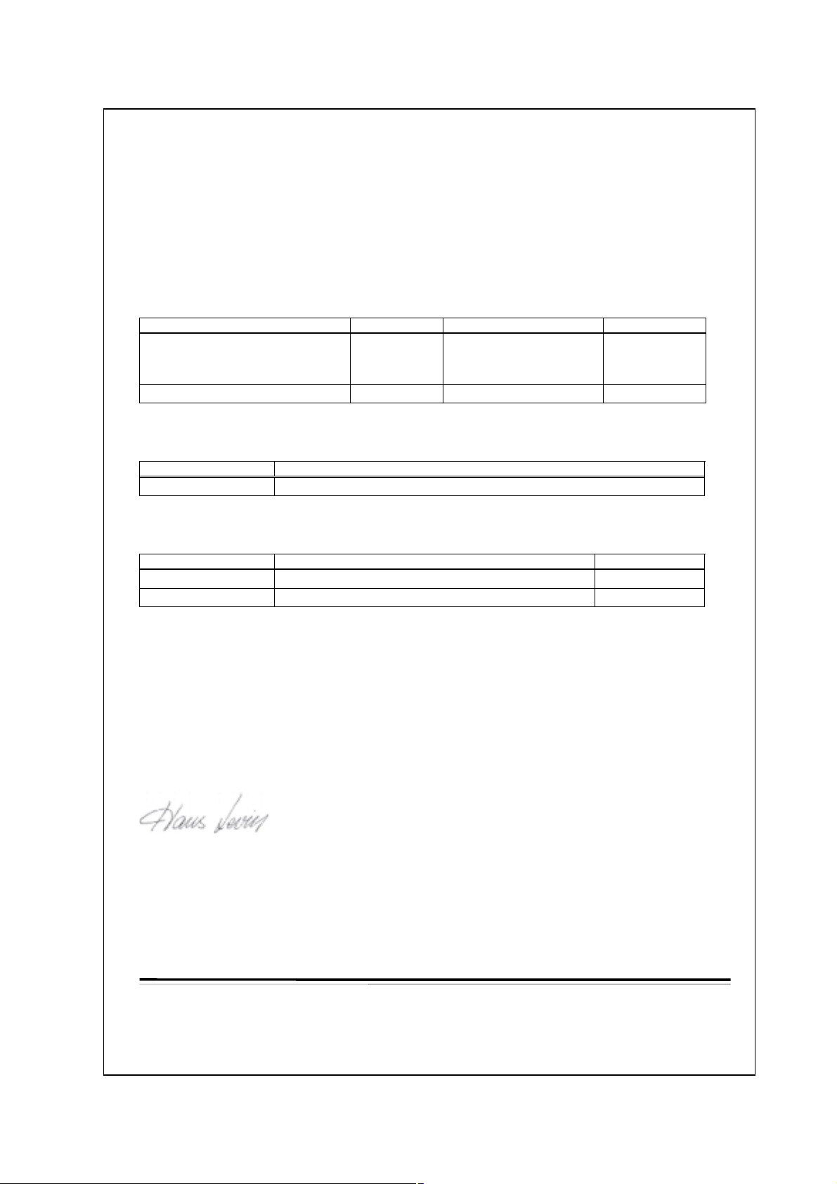
2.1. Declaration of Conformity
e
Westermo Teleindustri AB
Declaration of conformity
The manufacturer Westermo Teleindustri AB
SE-640 40 Stora Sundby, Sweden
herewith declares that the product(s)
Type of product Model Art no Installation manual
DIN-rail Fieldbus adapter FD-10 P
FD-10 A
FD-10 N
DIN-rail Fieldbus converter FD-40 3630-1400 6630-2242
is in conformity with the following EC directive(s).
No Title
89/336/EEG Electromagnetic Compatibility (EMC-directive)
3630-1100
3630-1101
3630-1102
6630-2212
References of standards applied for this EC declaration of conformity.
No Title Issue
EN 61000-6-2 Immunity for industrial environments 2 (2001)
EN 61000-6-4 Emission standard for industrial environments 1 (2001)
Hans Levin
Technical Manager
26th May 2003
Postadress/Postal address Tel. Telefax Postgiro Bankgiro Corp. identity number Registered office
S-640 40 Stora Sundby 016-61200 016-61180 52 72 79-4 5671-5550 556385-6367 Eskilstuna
Sweden Int+46 1661200 Int+46 1661180
Org.nr/ S‰t
Page 6
6 6630-2212
3. Introduction
The FD-10 is a PROFIBUS DP slave unit that is able to transfer PROFIBUS DP data via
leased lines,dialup modems or radio systems.The FD-10 is used to interface different
PROFIBUS DP networks.
All Westermo Fieldbus Adapters use the same protocol to communicate with each other
via serial interface.
3.1 Device types
There are three different types of FD-10 devices described in this manual:
• FD-10 P Point to point and Addressed, serial transfer slave
• FD-10 A Addressed,serial transfer master
• FD-10 N Network, serial sending
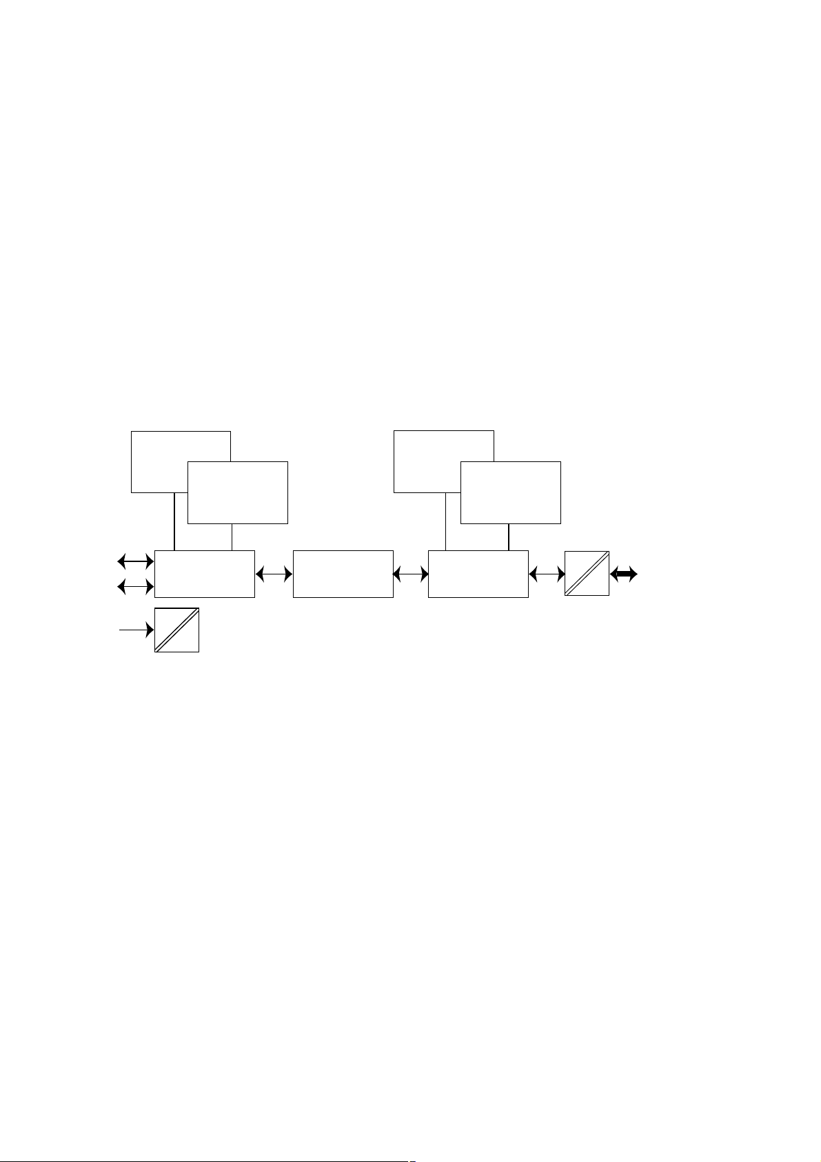
All device types are based on the same hardware architecture, schematically shown
below.
3.2 When are FD-10 devices useful?
Where a PROFIBUS DP net require connection to one or some PROFIBUS DP units
which are so located,that they:
• can’t be included in the net due to the distance,or
• reduce PROFIBUS DP data rate below the rated required for the system,or
• disturbance in PROFIBUS DP line (transmission line)
FD-10 will,together with the transfer units (modem), act as a interconnecting line
between two or many PROFIBUS DP nets.The interconnection line protocol handle
retransmission due to disturbances (e.g.due to the use of radio network or moving
trolleys),without any limitations at the PROFIBUS DP net.From the PROFIBUS DP
master point of view the whole system will be seen as a single PROFIBUS DP net,while
the master has all PROFIBUS I/O data handling with FD-10.
In data
PROFIBUS DP
In buffer
15k
Serial transfer
PROFIBUS DP
Master control
Interface
Serial transfer
control
Out data
PROFIBUS DP
Out buffer
15k
Serial T ransfer
RS-232
RS-485
Power
DC
DC
PROFIBUS DP
Page 7
76630-2212
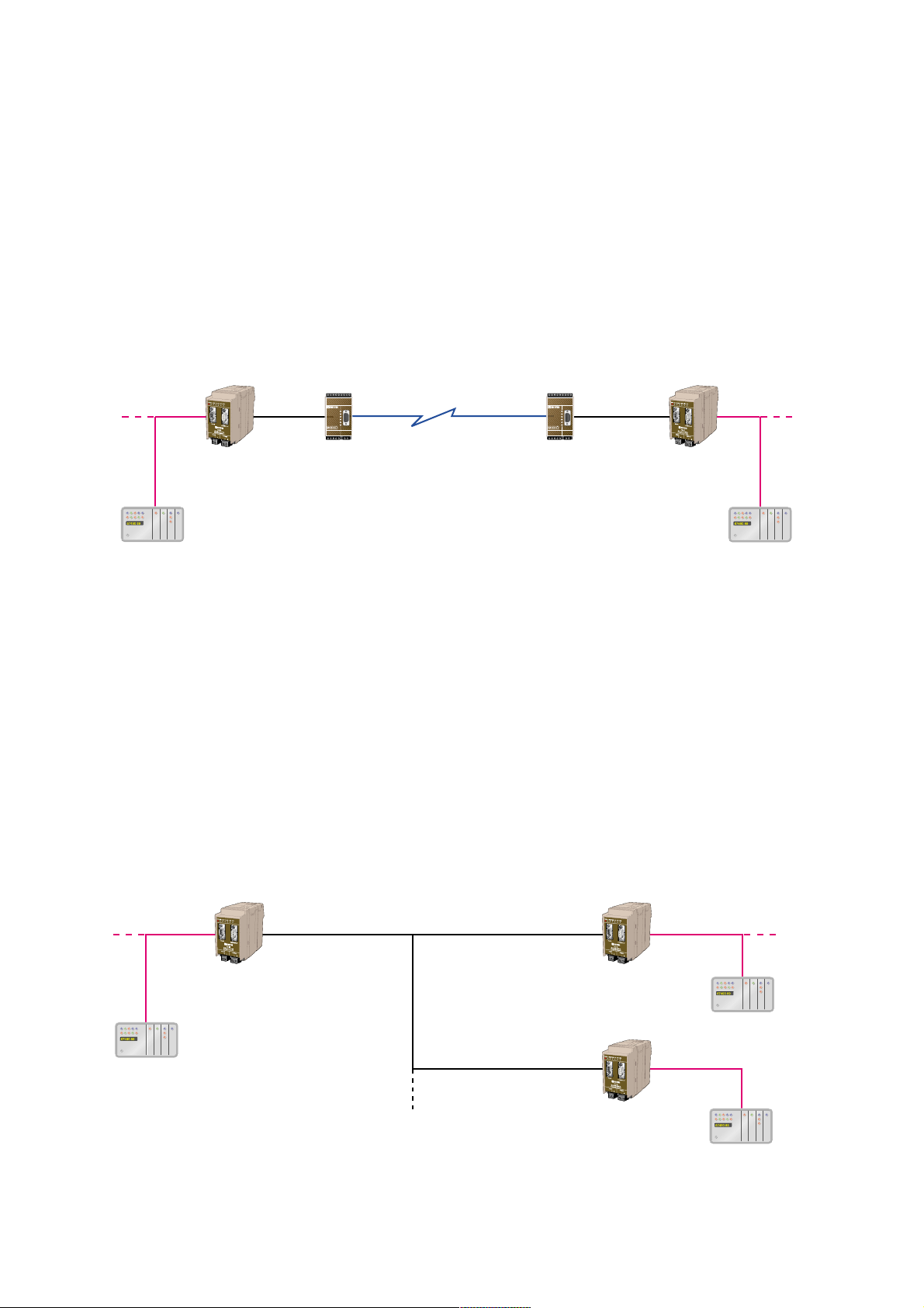
3.3 Field of application
Between Fieldbus adapters is PROFIBUS DP I/O data transferred over a transmission
line, divided in following type of applications:
• Point to point transfer
Continuous transfer of defined PROFIBUS I/O data modules between two FD-10’s.
This application is ideal when a high speed update of PROFIBUS DP data is required
and where no additional measures at installation is desired.
This application is realised by two FD-10 P (point to point mode) with an interconnecting line and modems,if required.
• Master controlled transfer (Addressed)
One transfer of defined PROFIBUS I/O data modules between two FD-10’s, on demand
from a PROFIBUS DP master. One FD-10 act as serial transfer master and can transfer
I/O data between various FD-10’s,selected by serial transfer address.This application is
ideal when a PROFIBUS DP master need connection to two,or more,independent
remote PROFIBUS DP systems.Radio system or RS-485 is typically used as transfer line.
Required additional measures,as serial transfer addressing.
This application is realised by one FD-10 A and one or many FD-10 P (addressed serial
transfer slave mode) with an interconnecting line and modems,if required.
FD-10 P
PROFIBUS DP
PROFIBUS DP
FD-10 P
Modem
(e.g PSTN*, Radio)
PROFIBUS DP
master
PROFIBUS DP
master
Modem
(e.g PSTN*, Radio)
FD-10 A FD-10 P
PROFIBUS DP
master
PROFIBUS DP
master
PROFIBUS DP
master
Serial
master
Serial
slave
Serial
slave
FD-10 P
PROFIBUS DP
PROFIBUS DP
PROFIBUS DP
* PSTN = Public Switch Telephone Transfer
123456789123456789
R+ R-T+ T- T+ T- R+ R-
CHANNEL 3
PWR
RD
TD
DCD2
DCD3
DCD4
CHANNEL 2 POWER
R+ R- T+ T12345
12-36V DC
- +
123456789123456789
R+ R-T+ T- T+ T- R+ R-
CHANNEL 3
PWR
RD
TD
DCD2
DCD3
DCD4
CHANNEL 2 POWER
R+ R- T+ T12345
12-36V DC
- +
Page 8

8 6630-2212
• Master controlled sending (Network)
Send defined PROFIBUS I/O data module once, from a FD-10 to an other.Sending data
on demand (event) from a PROFIBUS DP master.One of the included FD-10’s can send
I/O data to any other FD-10,selected by serial transfer address.This application is ideal
when data transfer between a number of PROFIBUS DP master systems is required.
Radio system or RS-485 is typically used as transfer line.Required additional measures,
as serial transfer addressing.
This application is realised by two or many FD-10 N with an interconnecting line and
modems,if required.
FD-10 N
PROFIBUS DP
master
PROFIBUS DP
PROFIBUS DP PROFIBUS DP
Modem
(e.g PSTN, Radio)
FD-10 N
PROFIBUS DP
master
Modem
(e.g PSTN, Radio)
FD-10 N
PROFIBUS DP
master
Modem
(e.g PSTN, Radio)
Page 9

96630-2212
4. Specifications
4.1 Interfaces
Power
Rated voltage 12–48 VDC
Operating voltage 9.6–57.6 VDC
Rated current 250 mA @ 12 V, 120 mA @ 24 V,60 mA @ 48 V
Rated frequency DC
Polarity Reverse polarity protected
Connection Screw terminal
Connector size 0.2–2.5 mm
2
(AWG 24–12)
Fuse To be externally fused
PROFIBUS DP
Electrical specification RS-485 / EN 50 170
Data rate 9.6, 19.2, 45.45, 93.75,187.5, 500,1 500, 3 000,6 000
and 12 000 kbit/s
Connection 9-position D-sub (female)
Termination External
Circuit type TNV-1
RS-485
Electrical specification RS-485/V.11
Data rate 1 200,2 400, 4 800,9 600, 14 400,19 200 and 38 400 bit/s
Connection 2-position screw terminal
Connector size 0.2 – 2.5 mm
2
(AWG 24-12)
Circuit type TNV-1
RS-232
Electrical specification RS-232/V.24
Data rate 1 200,2 400, 4 800,9 600, 14 400,19 200 and 38 400 bit/s
Connection 9-position D-sub,DTE
Circuit type SELV
Page 10

10 6630-2212
4.2 Insulation between interfaces
Power to all other 1.0 kV RMS @ 50Hz and 60 s duration
PROFIBUS DP to all other 1.0 kV RMS @ 50Hz and 60 s duration
Please note that there is no galvanic isolation between the RS-232 and the RS-485 ports so
they should not be connected simultaneously.
Internal
electronics
Power
PROFIBUS DP
RS-485
RS-232
NOTE:
Connect only one of RS-232
or RS-485 simultaneously
4.3 Climatic environment
Temperature, operating +5 to +55°C (optional industrial –25 to +70°C)
Temperature,
storage and transportation –25 to +70°C
Relative humidity,operating 5 to 95% (non-condensing)
Relative humidity,
storage and transportation 5 to 95% (condensation allowed outside packaging)
4.4 Mechanics
Dimension (W x H x D) 55 x 100 x 132 mm
Weight 0.3 kg
Mounting 35 mm DIN-rail
Degree of protection IP 20 (IEC 529)
Page 11

116630-2212
5. Maintenance
No maintenance is required, as long as the unit is used as intended within the specified
conditions.
6. Installation
6.1 Mounting /Removal
Before mounting or removing the unit:
Prevent damage to internal electronics from electrostatic discharges (ESD)
by discharging your body to a grounding point (e.g. use of wrist strap).
Prevent access to hazardous voltages by disconnecting the unit from AC/DC
mains supply and all other electrical connections.
Mounting
This unit should be mounted on 35 mm DIN-rail which is
horizontally mounted on a wall or cabinet backplate.
This unit uses convection cooling. To avoid obstructing the air
flow around the unit, use the following spacing rules.
Minimum spacing 25 mm (1.0 inch) above/below and 10 mm
(0.4 inches) left/right the unit.
Snap on mounting, see figure.
Removal
Press down the black support at the back of the unit
using a screwdriver, see figure.
Min
10 mm
25 mm
25 mm
!
CLICK!
Page 12

12 6630-2212
6.2 Connections
RS-232
PROFIBUS DP
RS-485
Power
Page 13

136630-2212
2-pos screw terminal Direction Description
No.1 – 0 V DC (–)
No.2 + +12 to +48 VDC (+)
6.2.2 Power
9-pos D-sub Direction Description
No.1 ––
No.2 ––
No.3 In/Out RxD/TxD-P
No.4 Out CNTR-P
No.5 – DGND
No.6 Out VP
No.7 ––
No.8 In/Out RxD/TxD-N
No.9 – DGND
6.2.3 PROFIBUS DP
9-pos D-sub Direction Description
No.1 ––
No.2 In Receive Data (RD)
No.3 Out Transmit Data (TD)
No.4 Out Data Terminal Ready (DTR)
No.5 – Signal ground (SG)
No.6 ––
No.7 Out Request To Send (RTS)
No.8 In Clear To Send (CTS)
No.9 ––
6.2.4 RS-232 (DTE)
1
2
2-pos screw terminal Direction Description
No.1 In/out T ransmit/Receiv e T/R+ (T+)
No.2 In/out T ransmit/Receiv e T/R– (T–)
6.2.5 RS-485
1
2
5
4
3
2
1
9
8
7
6
1
2
3
4
5
6
7
8
9
Female
Male
Page 14

14 6630-2212
6.3 Indicators
6.3.1 LED indicators
6.4 Configuration
Most of the FD-10 settings have to be carried out by Westermo FD-Tool, a PC based
configuration software,either on-line or off-line. Only RS-232 or RS-485 transfer settings
will be set by DIP switches.
6.4.1 DIP switch settings
DIP-switches are accessible under the lid on top of the unit.
Warning! Prevent damage to internal electronics from electrostatic discharges
(ESD)
by discharging your body to a grounding point (e.g. use of wrist
strap),before the lid on top of the modem is removed.
Warning! Do not open connected equipment.
Prevent access to hazardous voltages by disconnecting the unit from
AC/DC mains supply and all other electrical connections.
NOTE The change of DIP switch settings are valid only after a power on.
PWR LED on In service
LED off Out of service
BA LED on PROFIBUS DP active
LED off PROFIBUS DP inactive
CONF LED on Configuration mode
LED off Normal operation mode
TD LED on Transmit serial (RS-232/485) data
LED off –
RD LED on Receive serial (RS-232/485) data
LED off –
RTS LED on Request To Send (RTS) set
LED off –
CTS LED on Clear To Send (CTS) received active
LED off –
!
!
Page 15

156630-2212
Switch block 1
Serial transfer setting
Factory setting
S2:1-8
ON
1234
No RS-485 termination
ON
1234
RS-485 terminated by
120 Ω, with fail-safe
ON
1234
RS-232 selected as serial
transfer port, data control
ON
1234
RS-232 selected as serial
transfer port, RTS/CTS control
ON
1234
S1
RS-232 selected as serial
transfer port, data control.
No RS-485 termination
ON
1234
RS-485 selected as serial
transfer port
Note 1: Configuration by FD-Tool require factory setting (all S1 switches off).
Note 2: Switch 2 is not used.
S1:1-4
Page 16

16 6630-2212
6.4.2 On-line configuration by FD-Tool
This part will only describe the usage of FD-Tool to perform an on-line configuration.
For FD-Tool installation and general FD-Tool handling, see “FD-Tool installation manual”
on theCD,FD-Tool.
The FD-10 goes into configuration mode, a connection with FD-Tool,immediately after a
power on.The serial interface is set as follows, and should not be changed.
RS-232 9 600 bit/s no parity 8 data bits 1 stop bit data control
Initiate an on-line configuration
• Start the FD-Tool.
• Connect a DTE-DTE serial cable (zero-modem) to the serial port of the PC and the
RS-232 port of the FD-10.
• Initiate communication between the FD-Tool and the FD-10 by selecting Connect >
RS-232.The FD-Tool will attempt to get communication until a successful connection
or a manual cancel.
• Power the connected FD-10.The CONF LED of FD-10 will be active and remain so as
long as the FD-10 is in configuration mode. After some seconds, the connection will
established and the Status (to left in lower border of FD-Tool window) will be changed
from Disconnected to Connected.If the CONF LED will be inactive (after about
3 seconds),the initiation of on-line configuration is failed. If failed,check the serial
cable and that all S2 switches are set to off.Power on the device again.
• The FD-Tool shows the device type of this FD-10,present configuration, or the default
configuration whether the FD-10 is used for the first time.
Modify configuration
Configurations are defined per device type,see “Functional description”,chapter 7.
FD-10 P Point to point and Addressed, serial transfer slave
FD-10 A Addressed,serial transfer master
FD-10 N Network,serial sending
Load configuration to FD-10
• The present configuration,shown by FD-Tool, will be loaded to the FD-10 by selecting
File > Configuration > Load to device.
• This loaded configuration will be running in normal operation after a new power on
and when the CONF LED has been set to inactive.
Page 17

176630-2212
6.4.3 Off-line configuration by FD-Tool
This part will only describe the usage of FD-Tool to perform an off-line configuration.
For FD-Tool installation and general FD-Tool handling, see “FD-Tool installation manual.”
Initiate a new off-line configuration
• Start the FD-Tool.
• Select the device type by selecting File > Configuration > New (default / device)
and Select Group in Device Selection window. The selected group has to be the same
as the FD-10 device,for which the configuration will be used.
• FD-Tool will show the device type of this FD-10 for which all configuration parameters
have to be set.
Modify configuration
Configurations are defined per device type,see “Functional description”,chapter 7.
FD-10 P Point to point and Addressed, serial transfer slave
FD-10 A Addressed,serial transfer master
FD-10 N Network,serial sending
Load configuration to FD-10
• See “On-line configuration by FD-Tool”,chapter 6.4.2.
6.4.4 Save, load and modify configuration files by FD-Tool
Save configuration to disk
• The present configuration can be saved to disk as a file, to be used for future configurations of the same device type,by selecting File > Configuration > Save to disk
• An arbitrary file name can be used, saved as a *.cnf file.
Load and modify a disk stored configuration
• Load configuration from disk by selecting Configuration > Load from disk
and open the wanted configuration file (*.cnf).
• FD-Tool shows the device type of this FD-10 with the present configuration.
Page 18

18 6630-2212
Point to point Addressed Network
Device type FD-10 P FD-10 A FD-10 N
GSD-file FD-10.GSD FD-10.GSD FD-10.GSD
Device type Slave Slave Slave
Address range 0 to 126 0 to 126 0 to 126
Number Up to 8 Up to 8 2
of modules
Input data Up to 65 word/ Up to 65 word 16 word
130 byte
Output data Up to 65 word/ Up to 65 word 16 word
130 byte
Data control – One word for One word for
programming serial transfer serial transfer
control control
7. Functional description
Technical data
PROFIBUS DP data
Device
Serial transfer
Transfer type Slave Master Master
Transfer check 16 bit CRC 16 bit CRC 16 bit CRC
Transfer mode Point to Addressed Addressed Addressed
point transfer transfer sending
Serial address – 0 to 254 – 0 to 63
Connection Stat_Diag, Stat_Diag, Receive timeout, Receive
control number of timeout 1 500 ms timeout,
faild frames without 0 to 65 535 ms
1 to 255 frames
1 to 255 s
Page 19

196630-2212
7.1 Point to point and Addressed, serial transfer slave, FD-10 P
Point to point transfer
Continuous transfer of defined PROFIBUS I/O data modules from this FD-10 to an
other FD-10.
All by FD-Tool defined PROFIBUS I/O modules will be mirrored between the two
FD-10’s.Input modules of FD-10 at one side will be sent to output modules of FD-10
at the other side, and vice versa. However,note that there will be a time delay which
depends on the serial transfer time.
FD-10 continuously transfer I/O data,or try to initiate continuously transfer in the
initially stage, when the unit is in normal operation mode and the PROFIBUS DP is active,
LED CONF inactive and BA active.
Master controlled transfer (Addressed)
Wait for a received serial transfer frame including this unit’s serial transfer address.
After a correct received frame, an I/O data frame will be sent back once .
All by FD-Tool defined PROFIBUS I/O modules will be mirrored between this FD-10
and the FD-10 at the other side. Input modules of FD-10 will be sent to output modules
of FD-10 at the other side, and vice versa. Note that command and status data (including
this unit’s serial transfer address) will not be included in PROFIBUS I/O data of this
FD-10.
FD-10 can receive frames when the unit is in normal operation mode and the PROFIBUS
DP is active,LED CONF inactive and BA active.
Page 20

20 6630-2212
7.1.1 Basic configuration
Serial transfer > Transfer mode
Point – point Select Transfer slave point to point mode,with serial con-
nection to one Fieldbus Adapter. FD-10 will initiate and
begin continuous transfer of data with the other Fieldbus
Adapter.
Addressed slave Select Transfer slave addressed mode, with serial connec-
tion to one Fieldbus Adapter acting as transfer master.
FD-10 will wait for received data (including serial
address) from the Fieldbus Adapter master and send back
data once.
Address 0–254 Set this FD-10 Transfer slave address.Only needed when
Addressed slave has been selected.
Serial transfer > Serial interface
Select the desired parameters of the Serial interface.
PROFIBUS-DP > PROFIBUS DP parameters
PROFIBUS DP Address Set this FD-10 PROFIBUS DP address.
Number of I/O Modules Set the number of I/O modules used by this FD-10.
Module 1 and up to selected “Number of I/O Modules”
will be used by FD-10.
I/O module 1–4 > I/O module 1
Data type Select data type for I/O module 1.
Module type Select module type for I/O module 1.
Data length Set data length of I/O module 1.Note that data length is
related to selected data type,byte or word.Byte has a
length of 8 bit and word 16 bits.
Identifier [hex] Show the resulting identifier in hex.
The same content for all I/O modules,1 to 8. Module 1 and up to selected “Number of
I/O Modules” will be used by FD-10.
7.1.1.1 Expert configuration
Serial transfer > Expert parameters
Delay to send first byte Set the delay time before switching from send to receive,
in frame [ms] or vice versa.Default is 0. Used when serial transfer line
requires a turning time.
Max time between bytes Set the maximum allowed time between bytes in a serial
in frame [ms] frame. Default is 100. Useful when a frame will be divided
by transferring units (modem) which can cause a gap in
parts of the frame. Shall be less than “Min random delay
at initiation”.
Page 21

216630-2212
Min/max random delay Create a random delay until sending the initial frame at
at initiation [ms] point to point mode, to avoid collisions after start up or
at disturbed communication.Default is min 200 and max
500.For radio communications these times normally
need to be increased,min 500 and max 800 is recommended.
Fixed frame length Fixed 25 byte frame length.Should not be used.
20 data bytes Only when used together with old system.
Fixed frame length Fixed 37 byte frame length.Should not be used.
32 data bytes Only when used together with old system.
Variable frame length Should be selected for all Westermo Fieldbus Adapters.
1..249 data bytes
PROFIBUS-DP > Expert parameters
Enable/Disable Stat Diag When set to enable, the setting of the PROFIBUS DP
diagnostic information Stat_Diag (static diagnostics)
flag is enabled.Disable may be used when the PROFIBUS
DP master don’t handle Stat_Diag.Default is Enable.
Failed frames until set Only for Point to point transfer.
Stat Diag Set maximum number of consecutive sent frames without
any correct acknowledge.When exceeded will the
Stat_Diag flag be set.Default is 3. Can be increased if
transmission line is disturbed and that is acceptable.
Timeout until set Only for Addressed transfer.
Stat Diag Set maximum time in seconds since last received frame,
or time since device set in normal operation (power on),
without any new correct received frame. When time is
exceeded will the Stat_Diag flag be set.Default is 3. Can
be increased if it is long time between transfer of data
with this device and/or the transmission line is disturbed.
ID number Show the ID number of FD-10.Can’t be changed.
7.1.2 PROFIBUS DP I/O data
Ordinary PROFIBUS DP input and output data are used by FD-10.No additional
programming of the PROFIBUS DP master is needed for I/O data transfer.
Page 22

22 6630-2212
7.2 Addressed,serial transfer master,FD-10 A
Transfer defined PROFIBUS I/O data modules between two FD-10’s,each time on
demand by a PROFIBUS DP master.FD-10 A is the serial transfer master that transfer
I/O data between various FD-10’s,selected by serial transfer address.This serial address-
ing enable access to up to 255 independent remote PROFIBUS DP nets by only one
serial transmission line (e.g. radio system or RS-485).
By FD-Tool defined PROFIBUS I/O modules will be mirrored between FD-10 A and the
serial addressed FD-10 P at the other side.Input modules of FD-10 will be sent to output modules of FD-10 at the other side, and vice versa. Note that one data word command output and one data word status input has to be included in PROFIBUS I/O data
of FD-10 A.The command control the serial transfer and the status return information
about the transfer.
FD-10 can transfer frames when the unit is in normal operation mode and the
PROFIBUS DP is active,LED CONF inactive and BA active.
7.2.1 Basic configuration
Serial transfer > Serial interface
Select the desired parameters of the Serial interface.
PROFIBUS-DP > PROFIBUS DP parameters
PROFIBUS DP Address Set this FD-10 PROFIBUS DP address.
Number of I/O Modules Set the number of I/O modules used by this FD-10.
Module 1 and up to selected “Number of I/O Modules”
will be used by FD-10.
I/O module 1–4 > I/O module 1
Data type Select data type for I/O module 1.
Module type Select module type for I/O module 1.
Data length Set data length of I/O module 1.Note that data length is
related to selected data type,byte or word.Byte has a
length of 8 bit and word 16 bits.
Identifier [hex] Show the resulting identifier in hex.
The same content for all I/O modules,1 to 8. Module 1 and up to selected
“Number of I/O Modules” will be used by FD-10.
Page 23

236630-2212
7.2.1.1 Expert configuration
Serial transfer > Expert parameters
Max time between bytes Set the maximum allowed time between bytes in a serial
in frame [ms] frame. Default is 100. Useful when a frame will be divided
by transferring units (modem) which can cause a gap in
parts of the frame.
Fixed frame length Fixed 25 byte frame length.Should not be used.
20 data bytes Only when used together with old system.
Fixed frame length Fixed 37 byte frame length.Should not be used.
32 data bytes Only when used together with old system.
Variable frame length Should be selected for all Westermo Fieldbus Adapters.
1..249 data bytes
PROFIBUS-DP > Expert parameters
ID number Show the ID number of FD-10.Can’t be changed.
CPU type Hardware information.For service purpose only.
Can’t be changed.
7.2.2 PROFIBUS DP I/O data
Ordinary PROFIBUS DP I/O data are used by FD-10 A, including one data word in and
one out for the serial transfer control. Additional programming of the PROFIBUS DP
master to control I/O data transfer is needed,as defined below.
7.2.2.1 Output data word
Data transmitted from PROFIBUS DP master to FD-10 A.The first word is the serial
transfer command word and the remaining 2 to 65 words are ordinary output data
sent to addressed remote Fieldbus Adapter.
Out word 1 high byte (bit 15..8) is the serial transfer command byte,
with following content:
EN ENable FD-10 (bit15).
This bit must always be set high (1) for normal operation. When set, FD-10
indicates data set ready by the EN bit being set in the Input status word.EN
bit set to low (0) disable FD-10.
SDO Send actual Data Once , toggle bit (bit 14).
When this toggle bit change state, all out words are taken from DP output
data words and transmitted directly over the serial transfer interface of FD-10.
Word 15 High byte 8 7 Low byte 0
1 EN SDO – CNF RES – – – Transfer slave address, in range 0–254
2 Out data word 1, high byte Out data word 1, low byte
…… …
…… …
65 Out data word 64, high byte Out data word 64, low byte
Page 24

24 6630-2212
CNF CoNFiguration mode (bit 12).
For testing purpose only.
This bit is set low (0) during the normal operating mode of the FD-10. This bit
is set high (1) in order to switch the FD-10 over from normal operating mode
to configuration mode via PROFIBUS DP.
RES RESet read back status,toggle bit (bit 11).
When this toggle bit change state, it will reset read back status of ACK, TO
and all data input words.
Out word 1 low byte (bit 7..0) is the serial transfer address,with following content:
Transfer slave address of the Fieldbus Adapter to which this frame shall be
sent.Serial transfer slave address,in range 0 to 254.
Out word 2 to 65 is the output data,with following content:
Word 2 High: Output byte 1 Low: Output byte 2
Word 3 High: Output byte 3 Low: Output byte 4
......... ........ ......
Word 65 High:Output byte 127 Low: Output byte 128.
7.2.2.2 Input data word
Data is transmitted from the FD-10 A to the PROFIBUS DP master.The first word is the
added status word and the remaining 2 to 65 words are ordinary input data received
from the output word addressed remote Fieldbus Adapter.
Input word 1 high byte (bit 15..8) is the serial transfer status byte, with following content:
ST Status of serial transfer command FD-10 (bit15).
Set high (1) when the received command has been accepted by the FD-10.Set
low (0) if the received command has not been accepted.
DV Data Valid (bit 13).
For testing purpose only.
Acknowledgement of the command CNF.
ACK ACKnowledgement of serial transfer (bit 11).
Set high (1) when serial transfer sent output data to a remote FD-10 has
resulted in a received frame with input data from the remote FD-10.
TO Time Out received serial transfer (bit 10).
Set high (1) when the last serial transfer of output data to a remote FD-10 has
not resulted in any received frame within 1500 ms.
In word 1 low byte (bit 7..0) is not used.
In word 2 to 65 is the input data,with following content:
Word 15 High byte 8 7 Low byte 0
1 ST – DV – ACK TO – – – – – – – – – –
2 In data word 1, high byte In data word 1, low byte
…… …
…… …
65 In data word 64, high byte In data word 64, low byte
Page 25

256630-2212
Word 2 High:Input byte 1 Low:Input byte 2
Word 3 High: Input byte 3 Low: Input byte 4
......... ........ ......
Word 65 High:Input byte 127 Low: Input byte 128.
7.2.2.3 PROFIBUS DP communication
Required PROFIBUS DP communication sequence,from a PROFIBUS DP master unit to
FD-10 A,to get access and data exchange with remote Fieldbus Adapters.
Preparing for data exchange:
1. Enable normal operation access with FD-10 by command EN
Out word 1,bit 15 set high (1).
2. Verify accepted EN command by checking status ST.
In word 1,bit 15 shall be high (1).
Data exchange with a remote Fieldbus Adapter:
1. Set the Transfer slave address.
Out word 1,low byte to current serial transfer address.
2. Set Out data (up to 64 words) to this Transfer slave.
Out word 2 ...65.
3. Reset last received Input data and status by the command RES.
Out word 1,change state of toggle bit 11.
4. Transmit output data over serial transfer line by the command SDO.
Out word 1,change state of toggle bit 14.
5. Verify correct sent and received data by checking status ACK.
In word 1,bit 11 shall be high (1).
• Or,incorrect sent and received data,has not been received
within 1500 ms by checking status TO.
In word 1,bit 10 is set to high (1) in case of time out.
6. If correct received data will ACK be high (1) and TO low (0).
Read In data (up to 64 word) from addressed Fieldbus Adapter.
In word 2 ...65.
Page 26

7.3 Network,serial sending, FD-10 N
Send PROFIBUS in data from one FD-10 to an other FD-10 to be set as PROFIBUS out
data,on demand (event) by the PROFIBUS DP master in the sending PROFIBUS DP net.
One of the included FD-10’s can send I/O data to any other FD-10,selected by serial
transfer address.Note that the first data word,command output and one data word status input has to be included in PROFIBUS I/O data of FD-10.
Arbitrary FD-10 can send a frame to an other FD-10 at any time.This serial addressing
enable access to up to 64 independent remote PROFIBUS DP nets by only one serial
transmission line (e.g. radio system or RS-485).To reduce collisions on the transmission
line, the frequency or time between events resulting in sending has to be limited.
The degree of limitation depend on the number of FD-10’s and data rate of the serial
transfer.
FD-10 can send frames when the unit is in normal operation mode and the PROFIBUS
DP is active,LED CONF inactive and BA active.
7.3.1 Basic configuration
Serial transfer > Transfer mode
Network Address 0–64 Set this Transfer address of this FD-10.
Serial transfer > Serial interface
Select the desired parameters of the Serial interface.
PROFIBUS-DP > PROFIBUS DP parameters
PROFIBUS DP Address Set this FD-10 PROFIBUS DP address.
7.3.1.1 Expert configuration
Serial transfer > Expert parameters
Acknowledge timeout [ms] Set the maximum allowed time from sending a serial
transfer frame until received acknowledge.
The status TO will be set high (1) when this time has
been exceeded without any received acknowledge.
Default is 500.
Max time between bytes in Set the maximum allowed time between bytes in a serial
frame [ms] frame. Default is 100.Useful when a frame will be divided
by transferring units which can cause a gap in parts of the
frame.
PROFIBUS-DP > Expert parameters
ID number Show the ID number of FD-10.Can’t be changed.
I/O module 1–2 > I/O module 1
Identifier [hex] Show the 16 word input Identifier in hex.
Can’t be changed.
26 6630-2212
Page 27

276630-2212
I/O module 1–2 > I/O module 2
Identifier [hex] Show the 16 word output Identifier in hex.
Can’t be changed.
7.3.2 PROFIBUS DP I/O data
Ordinary 16 word PROFIBUS DP I/O data are used by FD-10 N,including one data word
in and one out for the serial transfer control. Additional programming of the PROFIBUS
DP master to control I/O data transfer is needed,as defined below.
7.3.2.1 Output data word
Data transmitted from PROFIBUS DP master to FD-10 N. The first word is the serial
transfer command word and the remaining 2 to 15 words are ordinary output data
sent to addressed remote Fieldbus Adapter.
Output word 1 high byte (bit 15..8) is the serial transfer command byte,
with following content:
EN ENable FD-10 (bit15).
This bit must always be set high (1) for normal operation.
When set the FD-10 indicates data set ready by the EN bit being set in the
Input status word.EN bit set to low (0) disable FD-10.
SDO Send actual Data Once , toggle bit (bit 14).
When this toggle bit change state, the data words are taken from the DP data
words and transmitted directly over the serial transfer interface of FD-10.
GTL Get TeLegram,toggle bit (bit 13).
When this toggle bit change state, the received serial transfer frame will be set
in the PROFIBUS DP input data.
CNF CoNFiguration mode (bit 12).
For testing purposes only.
This bit is set low (0) during normal operating mode of FD-10.
This bit is set high (1) in order to switch the FD-10 over from
normal operating mode to configuration mode.
RES RESet read back status,toggle bit (bit 11).
When this toggle bit change state, it will reset read back status ACK,NAK and
TO also in all data in words.
Word 15 High byte 8 7 Low byte 0
1 EN SDO GTL CNF RES – – – Transfer slave address in range 0–63
2 Out data word 1
…… …
…… …
16 Out data word 15
Page 28

28 6630-2212
Output word 1 low byte (bit 7..0) is the serial transfer address,with following content:
Transfer slave address of the Fieldbus Adapter to which this frame will be sent.
Serial transfer slave address,is in the range 0 to 64.
Output word 2 to 16 is the output data,with following content:
Word 2 Output data word 1
Word 3 Output data word 2
......... ........
Word 16 Output data word 15.
7.3.2.2 Input data word
Data is transmitted from the FD-10 N to the PROFIBUS DP master.The first word is the
added status word and the remaining 2 to 15 words are ordinary input data received
from the input word transfer slave addressed Fieldbus Adapter.
Input word 1 high byte (bit 15..8) is the serial transfer status byte, with following content:
ST STatus of serial transfer command FD-10 (bit15).
Set to high (1) when the received command has been accepted by the FD-10.
Set to low (0) if the received command has not been accepted.
DEX Data EXist (bit 14).
Set to high (1) when correct data is located in PROFIBUS DP
input data.
DV Data Valid toggle bit (bit 13).
This toggle bit change state, when the received serial transfer
frame data has been set in the PROFIBUS DP input data.
NAK No AcKnowledge (bit 12).
Set to high (1) when last transmitted serial transfer frame to a remote
FD-10 resulted in a received no acknowledge (NAK).
ACK ACKnowledge of serial transfer (bit 11).
Set to high (1) when last transmitted serial transfer frame to a remote
FD-10 resulted in a received acknowledge (ACK).
TO Time Out of serial transfer (bit 10).
Set to high (1) when last transmitted serial transfer frame to a remote
FD-10 has not resulted in any received ACK or NAK
within “Max time to acknowledge frame”.
Input word 1 low byte is the serial transfer address,with following content:
Transfer slave address of the Fieldbus Adapter from which this received
frame has been transmitted,only valid when DEX is
high (1).Serial transfer slave address,in the range 0 to 64.
Word 15 High byte 8 7 Low byte 0
1 ST DEX DV NAK ACK TO – – Transfer slave address in range 0–63
2 In word 1
……
……
16 In word 15
Page 29

296630-2212
Input word 2 to 16 is the input data,with following content:
Word 2 Input word 1
Word 3 Input word 2
......... ........
Word 16 Input word 15.
7.3.2.3 PROFIBUS DP communication
This describes the required PROFIBUS DP communication sequence from a PROFIBUS
DP master to an FD-10 N,to get access and data exchange with a remote FD-10 N.
Preparing for data exchange:
1. Enable normal operation access with FD-10 by command EN
Out word 1,bit 15 set high (1).
2. Verify accepted EN command by checking status ST
In word 1,bit 15 shall be high (1).
Send PROFIBUS DP data from local FD-10 N to remote FD-10 N:
1. Set the Transfer slave address.
Out word 1,low byte.
2. Set Out data to this Transfer slave.
Out word 2 ...16.
3. Reset Input word status by the command RES.
Out word 1,change state of toggle bit 11.
Transmit output data over serial transfer line by the command SDO.
Out word 1,change state of toggle bit 14.
4. Verify correct transmitted serial transfer frame by checking status ACK.
In word 1,bit 11 shall be high (1).
• Or incorrect transmitted,resulting in no acknowledge by checking status NAK.
In word 1,bit 12 is set to high (1) in case of no acknowledge.
• Or,incorrect transmitted,resulting in exceeding “Max time to acknowledge frame”
by checking status TO.
In word 1,bit 10 is set to high (1) in case of time out.
Receive PROFIBUS DP data from remote FD-10 N via local FD-10 N:
1. Wait for received frame by checking status DEX.
In word 1,bit 14 shall be high (1).
2. Set the received serial transfer frame in the PROFIBUS DP input data by the command GTL.
Out word 1,change state of toggle bit 13.
3. Wait until serial transfer frame data has been set in the PROFIBUS DP input data,by
checking whether the status bit DV has changed.
In word 1,toggle bit 13 shall change state.
4. Read the Transfer slave address of the Fieldbus Adapter from which this received
frame has been transmitted.
In word 1,low byte.
5. Read input data of PROFIBUS DP.
In word 2 ...16.
Page 30

30 6630-2212
OWN COMMENTS
.....................................................................................................................................................................................................................
.....................................................................................................................................................................................................................
.....................................................................................................................................................................................................................
.....................................................................................................................................................................................................................
.....................................................................................................................................................................................................................
.....................................................................................................................................................................................................................
.....................................................................................................................................................................................................................
.....................................................................................................................................................................................................................
.....................................................................................................................................................................................................................
.....................................................................................................................................................................................................................
.....................................................................................................................................................................................................................
.....................................................................................................................................................................................................................
.....................................................................................................................................................................................................................
.....................................................................................................................................................................................................................
.....................................................................................................................................................................................................................
Page 31

Page 32

T03-0261 • 6630-2212 03.05 Mälartryck AB, Eskilstuna, Sweden
Application examples
Westermo Teleindustri AB • SE-640 40 Stora Sundby,Sweden
Phone +46 16 42 80 00 Fax +46 16 42 80 01
E-mail:info@westermo.se
W estermo W eb site: www.westermo .com
Westermo Teleindustri AB have distributors in several
countries, contact us for further information.
Westermo Data Communications Ltd
Unit 14 Talisman Business Centre • Duncan Road
Park Gate, Southampton • SO31 7GA
Phone:+44(0)1489 580 585 • Fax.:+44(0)1489 580586
E-Mail:sales@westermo.co.uk
Westermo Data Communications GmbH
Goethestraße 67,68753 Waghäusel
Tel.: +49(0)7254-95400-0 • Fax.:+49(0)7254-95400-9
E-Mail:info@westermo.de
Westermo Data Communications S.A.R.L.
9 Chemin de Chilly 91160 CHAMPLAN
Tél :+33 1 69 10 21 00 • Fax :+33 1 69 10 21 01
E-mail :infos@westermo.fr
Subsidiaries
Modem
(e.g PSTN*, Radio,
Ethernet, GSM)
Modem
(e.g PSTN*, Radio,
Ethernet, GSM)
123456789123456789
PROFIBUS DP
master
I/O
FD-10 P
PROFIBUS DP
PROFIBUS DP
FD-10 P
PROFIBUS DP
master
I/O
Leased Line
PSTN*, Radio,
Ethernet, GSM
* PSTN = Public Switch Telephone Transfer
R+ R- T+ T- T+ T- R+ R-
CHANNEL 3
PWR
RD
TD
DCD2
DCD3
DCD4
CHANNEL 2 POWER
12-36V DC
R+ R- T+ T12345
- +
123456789123456789
R+ R- T+ T- T+ T- R+ R-
CHANNEL 3
PWR
RD
TD
DCD2
DCD3
DCD4
CHANNEL 2 POWER
12-36V DC
R+ R- T+ T12345
- +
 Loading...