

Page 1
User Guide
6609-2281
ED-200
SERIES
Westermo Teleindustri AB
©
ED-200
DIN-rail Serial router
ED-210
DIN-rail PSTN router
www.westermo.com
Page 2

2
6609-2281
Legal information
The contents of this document are provided “as is”. Except as required by applicable
law, no warranties of any kind, either express or implied, including, but not limited to,
the implied warranties of merchantability and fitness for a particular purpose, are made
in relation to the accuracy and reliability or contents of this document. Westermo
reserves the right to revise this document or withdraw it at any time without prior
notice.
Under no circumstances shall Westermo be responsible for any loss of data or income
or any special, incidental, and consequential or indirect damages howsoever caused.
More information about Westermo can be found at the following Internet address:
http://www.westermo.com
Page 3

3
6609-2281
Safety
!
!
Before installation:
Read this manual completely and gather all information on the unit. Make sure
that you understand it fully. Check that your application does not exceed the safe
operating specifications for this unit.
This unit should only be installed by qualified personnel.
This unit should be built-in to an apparatus cabinet, or similar, where access is
restricted to service personnel only.
The power supply wiring must be sufficiently fused, and if necessary it must be
possible to disconnect manually from the power supply. Ensure compliance to
national installation regulations.
This unit uses convection cooling. To avoid obstructing the airflow around the unit,
follow the spacing recommendations (see Cooling section).
Before mounting, using or removing this unit:
Prevent access to hazardous voltage by disconnecting the unit from all electrical
connections.
Warning! Do not open connected unit. Hazardous voltage may occur within this
unit when connected to TNV circuits.
Care recommendations
Follow the care recommendations below to maintain full operation of unit and to fulfil
the warranty obligations.
This unit must not be operating with removed covers or lids.
Do not attempt to disassemble the unit. There are no user serviceable parts inside.
Do not drop, knock or shake the unit, rough handling above the specification may cause
damage to internal circuit boards.
Do not use harsh chemicals, cleaning solvents or strong detergents to clean the unit.
Do not paint the unit. Paint can clog the unit and prevent proper operation.
Do not expose the unit to any kind of liquids (rain, beverages, etc). The unit is not water-
proof. Keep the unit within the specified humidity levels.
Do not use or store the unit in dusty, dirty areas, connectors as well as other mechanical
part may be damaged.
If the unit is not working properly, contact the place of purchase, nearest Westermo
distributor office or Westermo Tech support.
Warning! This unit may have hot surfaces when used at maximum rated ambient
temperature.
Maintenance
No maintenance is required, as long as the unit is used as intended within the specified
conditions.
Page 4

4
6609-2281
Agency approvals and standards compliance
Type Approval / Compliance
EMC EN 61000-6-2, Immunity industrial environments
EN 55024, Immunity IT equipment
EN 61000-6-4, Emission industrial environments
FCC part 15 Class A
EN 50121-4, Railway signalling and telecommunications apparatus
IEC 62236-4, Railway signalling and telecommunications apparatus
Safety EN 60950-1, IT equipment
PSTN (ED-210) ETSI TS103 021-1, ETSI TS103 021-2, ETSI TS103 021-3
FCC Part 15.105 Notice:
This equipment has been tested and found to comply with the limits for a
Class A digital device, pursuant to Part 15 of the FCC Rules. These limits
are designed to provide reasonable protection against harmful interference
in a residential installation. This equipment generates, uses and can radiate
radio frequency energy and, if not installed and used in accordance with
the instructions, may cause harmful interference to radio communications.
However, there is no guarantee that interference will not occur in a particular installation. If this equipment does cause harmful interference to radio
or television reception, which can be determined by turning the equipment
off and on, the user is encouraged to try to correct the interference by
one or more of the following measures:
… Reorient or relocate the receiving antenna
… Increase the separation between the equipment and receiver
… Connect the equipment into an outlet on a circuit different from that to
which the receiver is connected
… Consult the dealer or an experienced radio/TV technician for help.
Page 5

5
6609-2281
Declaration of Conformity
Westermo T eleindustri AB
Declaration of conformity
Org.nr/
Postadress/Postal address
Tel.
Telefax
Postgiro
Bankgiro Corp. identity number Registered office
S-640 40 Stora Sundby 016-428000 016-428001 52 72 79-4 5671-5550 556361-2604 Eskilstuna
Sweden Int+46 16428000 In t+46 16428001
The manufacturer Westermo Teleindustri AB
SE-640 40 Stora Sundby, Sweden
Herewith declares that the product(s)
Type of produc t Model Art no
DIN-rail Serial router ED-200 3609-5001
DIN-rail PSTN router ED-210 3609-5010
is in conformity with the following EC directive(s).
No Short name
2004/108/EC
Electromagnetic Compatibility (EMC)
2006/95/EC
Low Voltage Directive - LVD
1999/5/EC
RTTE Radio and Telecommunications Terminal Equipment
References of standards applied for this EC declaration of conformity.
No Title Issue
EN 61000-6-2 Immunity for industrial environments 2005
EN 61000-6-1 Immunity for residential, commercial and lightindustrial
environments
2007
EN 55024 Information technology equipment – Immunity 1998
+A1:2001
+A2:2003
EN 61000-6-4 EN 61000-6-4 2007
EN 60950-1 Safety of information technology equipment 2006 +A11:2009
The last two digits of the year in which the CE marking was affixed: 11
Herewith declares that product(s) listed above is in conformity with
No
Title
Issue
FCC part 15 Radio frequency devices
Pierre Öberg
Technical Manager
7th April 2011
Page 6

6
6609-2281
Type tests and environmental conditions
Electromagnetic Compatibility
Phenomena Test Description Test levels
ESD EN 61000-4-2 Enclosure contact ± 6 kV
RF field AM modulated IEC 61000-4-3 Enclosure 10 V/m 80% AM (1 kHz), 80 – 1 000 MHz
RF field 900 MHz ENV 50204 Enclosure 20 V/m pulse modulated 200 Hz, 900 ± 5 MHz
Fast transient EN 61000-4-4 Signal ports ± 2 kV
Surge EN 61000-4-5 Signal ports unbalanced ± 2 kV line to earth, ± 2 kV line to line
RF conducted EN 61000-4-6 Signal ports 10 V 80% AM (1 kHz), 0.15 – 80 MHz
Power frequency
magnetic field
Pulse magnetic field EN 61000-4-9 Enclosure 300 A/m, 6.4 / 16 µs pulse
Voltage dips and
interruption
Mains freq. 50 Hz EN 61000-4-16 Signal ports 100 V 50 Hz line to earth
Mains freq. 50 Hz SS 436 15 03 Signal ports 250 V 50 Hz line to line
Voltage dips and inter-
ruption
Radiated emission EN 55022 Enclosure Class A
Conducted emission EN 55022 AC power ports Class A
Dielectric strength EN 60950 Signal port to other
Environmental
Temperature Operating -25 to +65ºC
Humidity Operating 5 to 95% relative humidity
Altitude Operating 2 000 m / 70 kPa
Service life Operating 10 year
Vibration IEC 60068-2-6 Operating 7.5 mm, 5 – 8 Hz
Shock IEC 60068-2-27 Operating 15 g, 11 ms
Packaging
Enclosure UL 94 PC / ABS Flammability class V-1
Dimension W x H x D 55 x 100 x 132 mm
Weight 0.3 kg
Degree of protection IEC 529 Enclosure IP 20
Cooling Convection
Mounting Horizontal on 35 mm DIN-rail
EN 61000-4-8 Enclosure 100 A/m, 50 Hz, 16.7 Hz & 0 Hz
EN 61000-4-11 AC power ports 10 & 5 000 ms, interruption
EN 61000-4-29 DC power ports 10 & 100 ms, interruption
FCC part 15 Class A
FCC part 15 AC power ports Class A
EN 55022 DC power ports Class A
Enclosure air ± 8 kV
Power ports ± 2 kV
Signal ports balanced ± 2 kV line to earth, ± 1 kV line to line
Power ports ± 2 kV line to earth, ± 2 kV line to line
Power ports 10 V 80% AM (1 kHz), 0.15 – 80 MHz
10 & 500 ms, 30% reduction
100 & 1 000 ms, 60% reduction
10 ms, 30% reduction
10 ms, 60% reduction
+20% above & –20% below rated voltage
isolated ports
Power port to other
isolated ports
Storage & Transport -25 to +70ºC
Storage & Transport 5 to 95% relative humidity
2 kVrms 50 Hz 1 min
3 kVrms 50 Hz 1 min
2 kVrms 50 Hz 1 min (@ rated power <60 V)
2 g, 8 – 500 Hz
Page 7

7
6609-2281
Introduction
The ED-200 and ED-210 are two industrialised DIN Rail mounted Ethernet Routers.
The ED-200 has a serial interface that supports data rates up to 115 kbit/s. The ED-210
has an integrated PSTN modem. The device is easy to set-up using the integrated Web
tool. The dial-up networking functions in Microsoft Windows 9x, ME, NT, 2000, XP or
Vista can be used to make PPP connections to the unit. As well as any other platform
supporting the PPP protocol. Passwords can be used to increase the remote site security.
Once connected to the remote network all IP based protocols such asTCP, FTP, TELNET
and UDP can be used over the router. Ethernet connection to the units is via 100BaseTX
with support for QoS. The router features support for PPP (point to point) routing
protocol as well as NAT (Network Address Translation) and port forwarding/NAPT
(Network Address Port Translation).
Total galvanic isolation ensures that the data communication will not be effected by
ground loops or transfer electrical noise between communications ports. The high EMC
specification, like all other Westermo products ensures reliability of operation in the
harshest of site conditions.
Description
This manual specifies the ED-200 router series, the following products are included:
… ED-200 Serial router for connection in point-to-point applications or connection
to an external modem like ISDN, GSM etc.
… ED-210 PSTN router, a router for connection to a PSTN line. It can be used as
a dial in or dial out router or a point-to-point over leased line.
Configuration
The units can easily be configured via the onboard Web based configuration tool. Local
IP addresses can also be configured by using the Westernmo IP Config tool, from the IP
Config tool it is then possible to browse into the unit for further configuration.
In the ED-200 there is the option to use RS-422 for the PPP connection, termination of
the RS-422 interface is made using DIP-switches under the lid.
Page 8

8
6609-2281
Getting started
Help About
Scan for switches
Close
Default IP:
Device list:
IP Adress
Subnet Mask
MAC Adress SW Ver Type Status
192. 168. 2. 60
192.168.2.200 255.255.255.0 00-07-7C-80-4A-6C 9.74 ED-200
Mask:
255. 255. 255. 0
IP configuration
Access switch via web?
CancelOK
IP configuration
IP Address
When delivered, the default IP address of the ED-200 and ED-210 is 192.168.2.200.
Default gateway 192.168.2.200
If the default address of the unit is valid in the connected network it is possible to access
the unit directly from a web browser.
Change local IP address
The local address of ED-200/ED-210 can be configured using the IP Configuration tool,
then it is possible to browse into the unit for further configuration. The IP Configuration
program is available on the CD or for download from the WESTERMO web page:
http://www.westermo.com, (choose Downloads/Software/Ethernet/ED-200, ED-210
Name: setup.exe
Install the software and start the application from a PC on the network connected to the
same network as the ED-200/ED-210. Make sure that the Default IP of the configuration
software (see figure below) is in the same subnet as your PC.
Note! If you are not sure about the subnet – consult your network administrator.
Note! IP Config version must be 9.8.4 or higher.
Note! If you are not
sure about the settings
– consult your network
administrator.
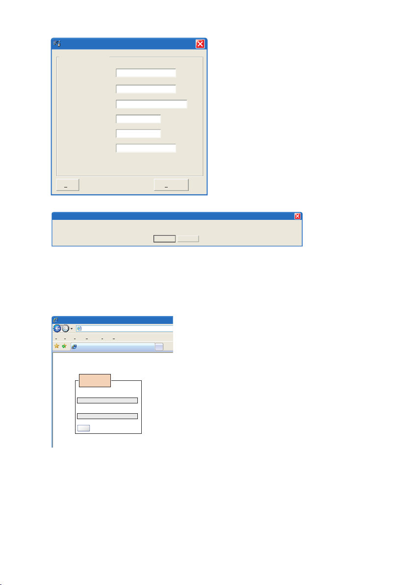
By clicking the “Scan for switches” button the IP Configuration tool will detect the switches/routers in
the network. The software will list all Westermo managed switches or routers connected to the network. Information as in the figure 1 will appear for each detected unit connected to the same network
as your PC.
If you only want to change the IP address and the subnet mask, this can be done
within the IP config tool.
By clicking the listed ED-200/ED-210 that you wish be re-configured you will be
asked if you would like to access via web figure 2. Click the abort button,
enter the preferred IP address, Subnet mask and IP gateway address and click the
Set button to confirm the settings in the unit (see figure 3).
Figure 1
Figure 2
Page 9
9
6609-2281
Click the Close button to get back to main view.
Selected Device
192
ED-200 configuration
IP adress:
IP gateway adress:
IP gateway adress:
Subnet mask:
MAC adress:
Host name:
Location:
168 2 200
192 168 2 200
255
Westermo
location
00 07 7C 80 4A 6C
255 255 0
Set Close
You have set new parameters on the switch. The switch must be restarted in order for the new parameters to take effect (except IP address change). Type cancel to return to
selected dialog or OK if you still want to quit.
CancelOK
IP configuration
Westermo - location - Provided by Westermo UK
http://192.168.2.200/conf/p.cgi Google
File Edit View Favorites Tools Help
Home Print Pa ge Tools
Westermo - location
Feeds (J)
Feeds (J)
Username:
Password:
Login
Login
You will then be asked if you would like to quit.
Click the OK button, figure 4, and you will be
back to the main view of the IP Configuration
program (see figure 1).
Figure 3
Click the Scan for switches button again and the settings you configured will appear in the list.
Now you can access the ED-200/ED-210 via the browser for further configuration by clicking the
unit with an IP address that fits your subnet. Figure 2 will appear and when you click the OK button
and a web browser will be opened and redirected to the ED-200./ED-210 unit log in page
(see figure 5).
Log in via Web
You will be prompted with a Login screen where
the default settings for Username and Password are:
Username: admin
Password: westermo
The unit can be easily configured via the on-board Web
based configuration tool, The network interface, serial
interface, PSTN, security and switch properties can now be
configured and stored. The Web tool have also an extended
integrated help function describing all configuration possibilities.
Note! Max 10 characters can be used in the login.
Note! For login, modem init and PPP authentication ASCII characters from 33 to 126 is valid except
for ASCII 34=”, ASCII 35=#, ASCII 39=’’, ASCII 40=( and ASCII 92=\.
Figure 5
Figure 4
Page 10
10
6609-2281
Diagnostic information
Restore Factory default settings
Under the lid there is a reset push button.
This will clear your customized settings and
restore the factory default settings.
Note! Do not disconnect power during the
factory reset process.
The process takes 90 second to complete if
the default address of the unit is valid on the connected network it is possible to access
the unit directly from a browser.
Simple Network Management Protocol (SNMP)
ED-200 and ED-210 supports Simple Network Management Protocol version 2c
(SNMPv2c). SNMP is an Internet standard protocol (IP) developed to manage IP nodes
(servers, workstations, routers, switches and hubs etc.) on an Ethernet network.
SNMP enables network administrators and controls engineers to manage network
performance, find and solve network problems, and plan for network growth.
The Lynx MIB’s are divided into groups allowing the SNMP manager to poll the SNMP
agents for information. The parts of the following MIB groups are implemented and can
be found on CD.
… General MIB … MIB-2
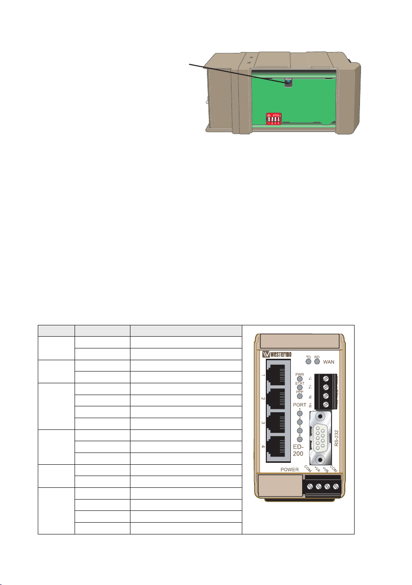
Location of Interface ports, LED’s and DIP-switches
LED indicators
LED Status Description
RD Flashing Receiving data from WAN port
OFF –
TD Flashing Transmitting data to WAN port
OFF –
PWR ON-green Start up ready
ON-yellow Booting
Flashing green Connected with IPconfig tool.
OFF No power
STAT ON-green Start up ready
ON-yellow Indicating active alarm
OFF –
PPP ON PPP-link established
OFF –
Port 1–4 ON-green Link active
Flashing-green Traffic on link
ON-yellow Indicating alarm
OFF –
Page 11

11
6609-2281
Interface specifications ED-200
Power
Rated voltage 12 to 48 VDC
Operating voltage 10 to 60 VDC
Rated current ED-200 360 mA @ 12 VDC
Rated frequency DC
Inrush current, I2t ED-200 0,51 A2s
Startup current* ED-200 1 A
Polarity Reverse polarity protected
Redundant power input Yes
Isolation to Ethernet, RS-232, RS-422
Connection Detachable screw terminal
Connector size 0.2 – 2.5 mm2 (AWG 24 – 12)
Shielded cable Not required
* External supply current capability for proper startup
RS-422
Electrical specification EIA RS-422 4-wire twisted pair
Data rate 300 bit/s - 115.2 kbit/s
Data format 8 data bits, none parity, 1 stop bit
Protocol PPP
Transmission range ≤ 1200 m, depending on data rate and cable type (EIA RS-422)
Settings 120 Ω termination and failsafe biasing 680 Ω
Protection Installation Fault Tolerant (up to ±60 V)
Isolation to Power and Ethernet
Galvanic connection to RS-232
Connection Detachable screw terminal
Connector size 0.2 – 2.5 mm2 (AWG 24 – 12)
Shielded cable Not required
ED-200 180 mA @ 24 VDC
ED-200 100 mA @ 48 VDC
RS-232
Electrical specification EIA RS-232
Data rate 300 bit/s - 115.2 kbit/s
Data format 8 data bits, none parity, 1 stop bits
Protocol PPP
Transmission range 15 m
Isolation to Power and Ethernet
Galvanic connection to RS-422
Connection 9-pin D-sub male (DTE)
Shielded cable Not required
Ethernet TX
Electrical specification IEEE std 802.3. 2000 Edition
Data rate 10 Mbit/s, 100 Mbit/s, manual or auto. IEEE 802.3 2000 edition.
Duplex Full or half, manual or auto
Transmission range 100 m
Isolation to Power, RS-232 and RS-422
Connection RJ-45
Shielded cable Shielded cable is required if unit is used in harsh environment
Number of ports 4 ports marked as 1, 2, 3, 4
Page 12

12
6609-2281
ED-200 Connections
Ethernet TX
Position Direction* Description
1 In/Out Transmitted/Received data
2 In/Out Transmitted/Received data
3 In/Out Transmitted/Received data
4 – NC
5 – NC
6 In/Out Transmitted/Received data
7 – NC
8 – NC
Power screw terminal
Position Direction* Description Product marking
1 In Common voltage COM
2 In Voltage A +VA
3 In Voltage B +VB
4 In Common voltage COM
RS-232 D-sub**
Position Direction* Description
1 In Data Carrier Detect (DCD)
2 In Received Data (RD)
3 Out Transmitted Data (TD)
4 Out Data Terminal Ready (DTR)
5 – Signal Ground (SG)
6 In Data Set Ready (DSR)
7 Out Request To Send (RTS)
8 In Clear To Send (CTS)
9 In Ring Indicator (RI)
RS-422 screw terminal**
Position Direction* Description Product marking
1 In R+ (EIA RS-422 A’) R+
2 In R– (EIA RS-422 B’) R–
3 Out T+ (EIA RS-422 A) T+
4 Out T– (EIA RS-422 B) T–
* Direction relative this unit
** TShielded cable is required if unit is used in harsh environment.
Page 13

13
6609-2281
Interface specifications ED-210
Power
Rated voltage 12 to 48 VDC
Operating voltage 10 to 60 VDC
Rated current ED-210 370 mA @ 12 VDC
Rated frequency DC
Inrush current, I2t ED-210 1,1 A2s
Startup current* ED-210 1,1 A
Polarity Reverse polarity protected
Redundant power input Yes
Isolation to Ethernet and PSTN
Connection Detachable screw terminal
Connector size 0.2 – 2.5 mm2 (AWG 24 – 12)
Shielded cable Not required
Ethernet TX
Electrical specification IEEE std 802.3. 2000 Edition
Data rate 10 Mbit/s, 100 Mbit/s, manual or auto. IEEE 802.3 2000 edition.
Duplex Full or half, manual or auto
Transmission range 100 m
Isolation to Power, RS-232 and RS-422
Connection RJ-45
Shielded cable Shielded cable is required if unit is used in harsh environment
Number of ports 4 ports marked as 1, 2, 3, 4
PSTN
Electrical specification Public Switched Telephone Network
Data rate 600 bit/s – 33.6 kbit/s
Protocol Bell103, Bell212, V.21, V.22, V.22Bis, V.23C, V.32, V.32Bis, V.34
Protection Installation Fault Tolerant (up to ±60 V)
Connection RJ-11C
Shielded cable Not required
ED-210 190 mA @ 24 VDC
ED-210 110 mA @ 48 VDC
Page 14
14
6609-2281
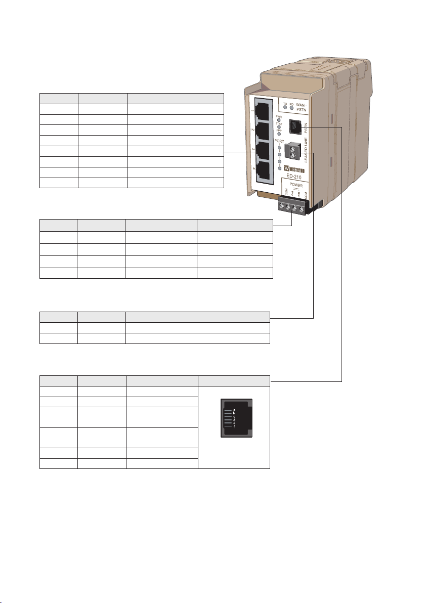
ED-210 Connections
Ethernet TX
Position Direction* Description
1 In/Out Transmitted/Received data
2 In/Out Transmitted/Received data
3 In/Out Transmitted/Received data
4 – NC
5 – NC
6 In/Out Transmitted/Received data
7 – NC
8 – NC
Power screw terminal
Position Direction* Description Product marking
1 In Common voltage COM
2 In Voltage A +VA
3 In Voltage B +VB
4 In Common voltage COM
Leased line connection**
Position Direction* Description
1 In/Out 2-wire Receive/ Transmit
2 In/Out 2-wire Receive/ Transmit
PSTN connection
RJ-11C Direction* Description Product marking
a NC
b NC
c In/Out PSTN Transmit/
Receive
d In/Out PSTN Transmit/
Receive
e NC
f NC
* Direction relative this unit
** Tested leased line speed in harsh environmental is 9600 bit/s.
Page 15
15
6609-2281
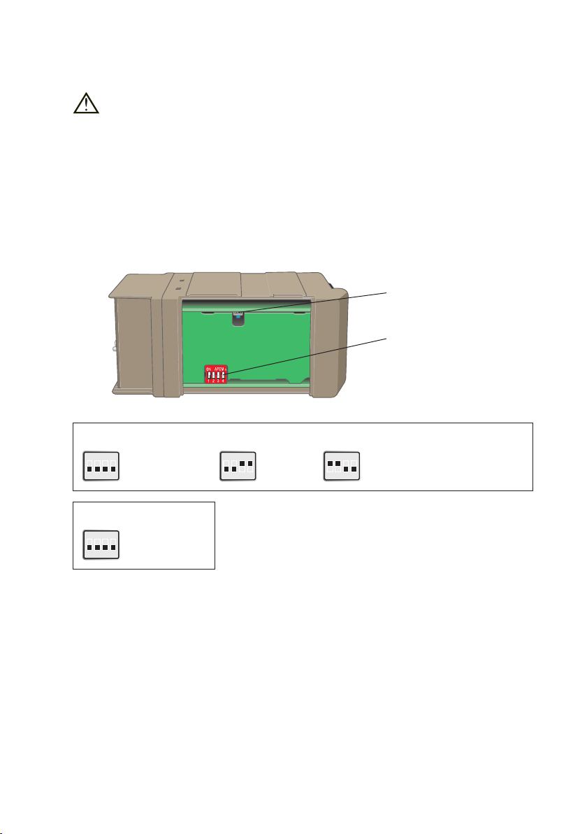
DIP-switch settings for ED-200
Before setting DIP-switches:
Prevent damage to internal electronics from electrostatic discharges (ESD)
by discharging your body to a grounding point (e.g. use of wrist strap).
Reset switch
The reset button can be used to make a make a factory reset of the unit.
All settings will return to factory default.
Note! Do not disconnect power during the factory reset process.
The process takes 90 second to complete.
Reset botton
DIP-switch
RS-422 termination
ON
1 2 3 4
No termination or
failsafe
ON
1 2 3 4
Not used
ON
1 2 3 4
Termination of receiver
with failsafe; R+ and R–
Factory settings
ON
1 2 3 4
Page 16

16
6609-2281
CLICK!
Mounting
This unit should be mounted on 35 mm DIN-rail, which is
horizontally mounted inside an apparatus cabinet, or similar.
Snap on mounting, see figure.
Cooling
This unit uses convection cooling. To avoid
obstructing the airflow around the unit, use the
following spacing rules. Minimum spacing 25 mm
(1.0 inch) above /below and 10 mm (0.4 inches)
left /right the unit. Spacing is recommended for
the use of unit in full operating temperature
range and service life.
* Spacing (left/right) recommended for
full operating temperature range
10 mm *
(0.4 inches)
25 mm
25 mm
Removal
Press down the black support at the back of the unit
using a screwdriver, see figure.
Page 17

17
6609-2281
Application examples
TDW-33 / TD-36
GDW-11 / IDW-90
ED-200
PSTN / GSM / ISDN
Leased Line
ED-200 ED-200TD-36TD-36
ED-210
PSTN
… Remote connection dial in router
The ED-200 has an RS-232 serial interfaces that allows connection of different types
of modem to the router.
… LAN- LAN (on leased line)
The ED-200 can be used to connect two different IP networks together.
The leased line connection can be established by using a PSTN modem with support
for leased line (TD-36) or by direct connection via the RS-422 interface on the
ED-200. If RS-422 is used, the range is limited to 1200 metres according to the RS-422
standard.
… Remote connection dial in router using ED-210
The ED-210 has an integrated PSTN modem with support for V.34. The integrated
modem has the same specification as the Westermo TDW-33 telephone modem.
Page 18

18
6609-2281
… Routing with NAT and port forwarding (NAPT)
NAT
and
NAPT
PSTN
By using NAT (Network Address Translation) it is possible to “hide” all local IP
addresses. Access to all devices is via the IP address of ED-200/ED-210.
Port forwarding makes it possible to access different ports (applications) on a unit
located on the local network eg the HTTP (port 80) or a Telnet session (port 23).
For more information on applications and technical data visit www.westermo.com.
The Web tool also includes an integrated help where all functions and modes are
described in details.
More help can be found inside the web tool and the ”?” button
on each configuration page.
Page 19

Page 20

Westermo Teleindustri AB • SE-640 40 Stora Sundby, Sweden
Phone +46 16 42 80 00 Fax +46 16 42 80 01
E-mail: info@westermo.com
Westermo Web site: www.westermo.com
Sweden
Westermo Data Communications AB
Svalgången 1
SE-724 81 Västerås
Phone: +46 (0)21 548 08 00 • Fax: +46 (0)21 35 18 50
E-Mail: info.sverige@westermo.se
United Kingdom
Westermo Data Communications Ltd
Talisman Business Centre • Duncan Road
Park Gate, Southampton • SO31 7GA
Phone: +44(0)1489 580-585 • Fax.:+44(0)1489 580586
E-Mail: sales@westermo.co.uk
Germany
Westermo Data Communications GmbH
Goethestraße 67, 68753 Waghäusel
Tel.: +49(0)7254-95400-0 • Fax.:+49(0)7254-95400-9
E-Mail: info@westermo.de
France
Westermo Data Communications S.A.R.L.
9 Chemin de Chilly 91160 CHAMPLAN
Tél : +33 1 69 10 21 00 • Fax : +33 1 69 10 21 01
E-mail : infos@westermo.fr
Sales Units
Singapore
Westermo Data Communications Pte Ltd
2 Soon Wing Road #08-05
Soon Wing Industrial Building
Singapore 347893
Phone +65 6743 9801 • Fax +65 6745 0670
E-Mail: sales@westermo.com.sg
North America
Westermo Data Communications
939 N. Plum Grove Road, Suite F
Schaumburg
Chicago
Phone: +1 847 619 6068
Fax: +1 847 619 66 74
E-mail: info@westermo.com
Taiwan
Westermo Data Communications Co
F2, No. 188, Pao-Chiao Rd.
Shing-Tien City
Taipei 23145
Phone:+886 2 8911 1710
E-mail: info@westermo.com
Westermo Teleindustri AB have distributors in several countries, contact us for further information.
REV.B 6609-2281 2011.04 Westermo Teleindustri AB, Sweden – A Beijer Electronics Group Company
 Loading...