

Page 1

PPP Router
INSTALLATION MANUAL
6609-2222
www.westermo.com
ED-20 PPP
©
Westermo Teleindustri AB • 2004 • REV.A
Galvanic
Isolation
Transient
Protection
Balanced
Transmission
CE
Approved
Page 2

2 6609-2222
Contents
1. Description .................................................................................................................................................................. 3
2. Safety .................................................................................................................................................................................. 4
3. Approvals ....................................................................................................................................................................... 4
3.1 Declaration of Conformity ....................................................................................................................... 5
4. Specification ........................................................................................................................................................ 6–7
5. Maintenance .............................................................................................................................................................. 8
6. Installation .......................................................................................................................................................... 8–15
6.1 Mounting/Removal .......................................................................................................................................... 8
6.2 Connections ................................................................................................................................................ 9–11
6.3 Settings ................................................................................................................................................................. 12
6.3.1 Ethernet Router ................................................................................................................................. 12
6.3.1.1 DIP Switch Settings ................................................................................................... 12–13
6.3.2 Configuration ports ......................................................................................................................... 14
6.3.3 LED indicators .................................................................................................................................... 14
6.4 MAC address .................................................................................................................................................... 15
6.5 Installation of ED-Tool for ED-20 .................................................................................................... 15
7. Functional description .................................................................................................................... 16–17
7.1 Application mode ......................................................................................................................................... 16
7.1.1 About PPP .............................................................................................................................................. 16
7.1.2 Network interfaces .......................................................................................................................... 16
7.1.2.1 Ethernet connection ........................................................................................................... 16
7.1.2.2 PPP connection ....................................................................................................................... 16
7.1.2.3 Brouter function ..................................................................................................................... 17
7.1.2.4 Firewall function ..................................................................................................................... 17
7.1.2.5 Proxy ARP function .............................................................................................................. 17
7.2 Configuration mode .................................................................................................................................. 17
8. Configuration .............................................................................................................................................. 18–31
8.1 Configuration by ED-Tool for ED-20 ............................................................................................. 18
8.1.1 ED-Tool for ED-20 commands ................................................................................................ 19
8.1.1.1 General commands ............................................................................................................. 19
8.1.1.2 Serial Interface – Channel 1 specific commands .......................................... 19
8.1.1.3 Modem Settings ............................................................................................................ 20–21
8.1.1.4 Network Settings .................................................................................................................. 22
8.1.1.5 Brouter Settings ..................................................................................................................... 23
8.1.1.6 Firewall Settings ..................................................................................................................... 24
8.2 Configurable parameters .............................................................................................................. 25–31
8.2.1 Serial interface .................................................................................................................................... 25
8.2.2 Modem settings ........................................................................................................................ 25–29
8.2.3 Network Settings .................................................................................................................... 29–30
8.2.4 Brouter settings ........................................................................................................................ 30–31
8.2.5 Firewall Settings ................................................................................................................................ 31
9. Application examples ....................................................................................................................... 32–35
Page 3
36609-2222
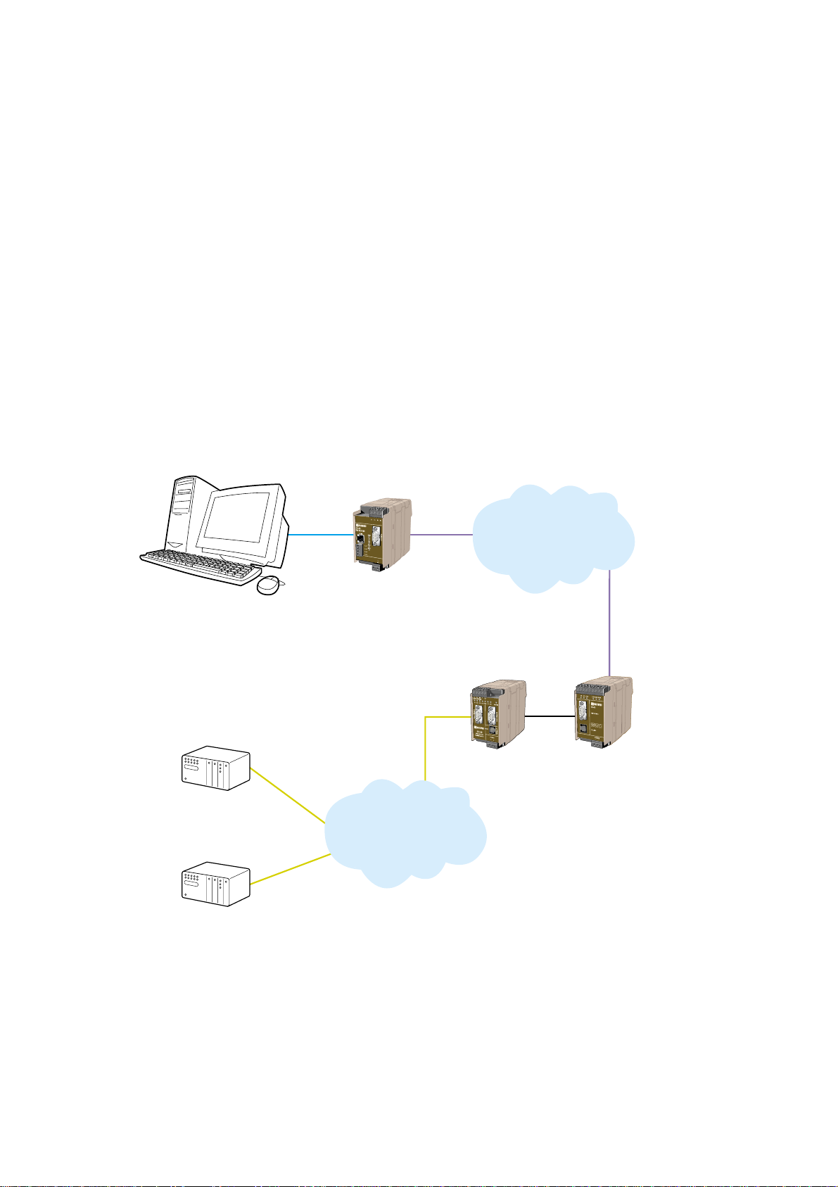
1. Description
The ED-20 is an industrialised DIN Rail mounted, serial to Ethernet Router. The device
will allow access to a remote Ethernet network via a Westermo communication product.
The device is easy to set-up using the ED-Tool for ED-20, via TELNET or serial connection.
Standard PPP dial-up networking tools can be used from Microsoft Windows 9x, ME, NT,
2000 or XP. Any other platform supporting the PPP protocol could equally be used.
Passwords are provided to increase the remote site security. Once connected to the
remote network all TCP/IP, FTP,TELNET and UDP protocol types can be used.
Connection to the ED-20 is via 10Base-T on the Ethernet and RS-232 on the serial side.
The serial port supports speeds up to 115 kbit/s.
Total galvanic isolation ensures that the data communication will not be effected by
ground loops or transfer electrical noise between communications ports.The high EMC
specification, like all other Westermo production ensures reliability of operation in the
harshest of site conditions.
ED-20
TD-33
TD-35
PSTN
TCP/IP
Ethernet
Page 4

4 6609-2222
2. Safety
General:
Before using this unit, read this manual completely and gather all information on
the unit. Make sure that you understand it fully. Check that your application does
not exceed the safe operating specifications for this unit.
Before installation, maintenance or modification work:
Prevent damage to internal electronics from electrostatic discharges (ESD)
by discharging your body to a grounding point (e.g. use of wrist strap).
Prevent access to hazardous voltages by disconnecting the unit from AC/DC
mains supply and all other electrical connections.
Installation:
This unit should only be installed by qualified personnel.
This unit should only be installed in a “restricted access area”, for example
a lockable cabinet where access is restricted to service personnel only.
This unit is intended for permanent connection to the AC/DC mains supply.
The power supply wiring must be sufficiently fused, and if necessary it must be
possible to disconnect manually from the AC/DC mains supply. Ensure compliance
to national installation regulations.
Units with the rated voltage exceeding 42.4 V peak or 60 VDC, are defined as
class I equipment with a protective earthing conductor terminal.
Units with the rated voltage up to 42.4 V peak or 60 VDC, are defined as class III
equipment and shall be separated from hazardous voltage by double or reinforced
insulation.
This unit uses convection cooling.To avoid obstructing the air flow around the
unit, follow the spacing recommendations (see Installation section).
3. Approvals
Conformity with the Directive 89/339/EEC (Electromagnetic compatibility)
has been assessed by application of standards EN 61000-6-2 (industrial immunity)
and EN 61000-6-4 (industrial emission).
!
!
!
Page 5

56609-2222
3.1 Declaration of Conformity
Page 6

6 6609-2222
4. Specification
ED-20
Rated voltage 12 – 48 VDC (polarity independent)
Operating voltage 9.6 – 57.6 VDC
Rated current 300 mA @ 12 VDC
Rated frequency DC
Connection Detachable screw terminal
Connector size 0.2 – 2.5 mm
2
(AWG 24-12)
Power interface
Ethernet TX Interface 10Base-T
Electrical specification IEEE std 802.3. 2000 edition
Data rate 10 Mbit
Duplex Half
Connection RJ-45
Circuit type TNV-1
Transmission range 100 m
RS-232 Interface 1 (CH-1)
Electrical specification RS-232 V.24
Data rate 1200 bit/s – 115.2 kbit/s
Connection 9-pol. D-sub female DCE
Circuit type SELV
RS-232 Interface 2 (CH-2)
Electrical specification RS-232 V.24
Data rate 19.2 kbit/s
Connection 9-pol. D-sub female DCE
Circuit type SELV
RS-422 Interface (CH-1)
Electrical specification RS-422
Data rate 1200 bit/s – 115.2 kbit/s
Connection Detachable screw terminal
Connector size 0.2 mm
2
– 2.5 mm2(AWG 24-12)
Circuit type TNV-1
Page 7

76609-2222
Mechanical
Dimension (W x H x D) 55 x 100 x 128 mm
Weight <0.35 kg
Mounting DIN-rail
Degree of protection IP 20 (IEC 529)
Isolation between interfaces
Power to all other* 4.2 kV DC, 3 kV RMS @ 50 Hz and 60s duration
TX signal Interface to all other 2.1 kV DC, 1.5 kV RMS @ 50 Hz and 60s duration
TX shield Interface to all other 1.5 kV DC, 1 kV RMS @ 50 Hz and 60 s duration
Environmental
Temperature, operating +5 to +50°C
Temperature, storage
and transportation –25 to +70°C
Relative humidity, operating 5 to 95% (non-condensing)
Relative humidity,
storage and transportation 5 to 95% (condensation allowed outside packaging)
Configuration
Configuration of the Router is made with DIP-switches and with ED-tool for ED-20
locally via RS-232 port or remotly via Ethernet.
* Power to network interface, 2.1 kV DC, 1.5 kV RMS @ 50 Hz and 60 s duration.
Page 8

8 6609-2222
5. Maintenance
No maintenance is required, as long as the unit is used as intended within the specified
conditions.
6. Installation
6.1 Mounting / Removal
Before mounting or removing the unit:
Prevent damage to internal electronics from electrostatic discharges (ESD) by discharging your body to a
grounding point (e.g. use of wrist strap).
Prevent access to hazardous voltages by disconnecting
the unit from AC/DC mains supply and all other electrical connections.
Mounting
This unit should be mounted on 35 mm DIN-rail which is
horizontally mounted on a wall or cabinet backplate.
This unit uses convection cooling.To avoid obstructing the
airflow around the unit, use the following spacing rules.
Recommended spacing 25 mm (1.0 inch) above/below and
10 mm (0.4 inches) left/right the unit.
Snap on mounting, see figure
Removal
Press down the black support at the back of the unit
using a screwdriver, see figure.
10 mm *
(0.4 inches)
25 mm
25 mm
* Spacing (left/right) recommended
for full operating temperature range
!
!
K
C
I
L
C
Page 9
96609-2222
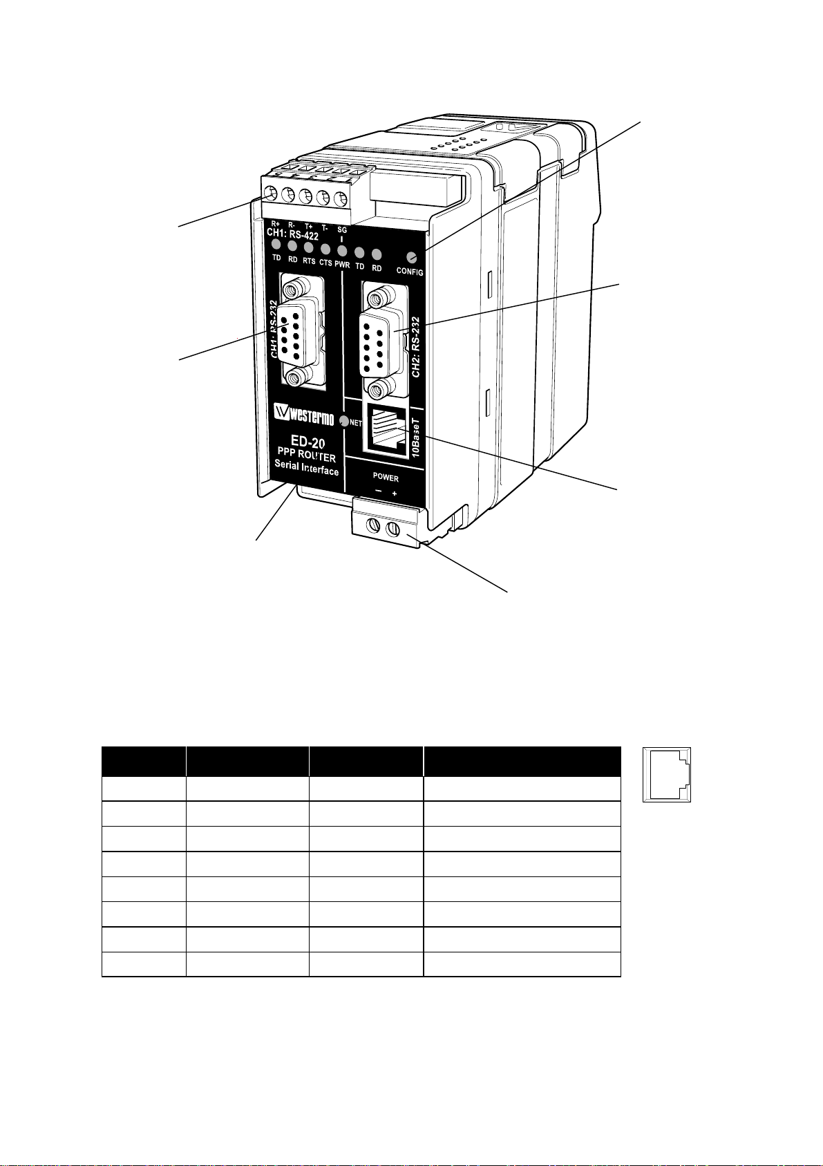
6.2 Connections
Power
LED indicators
LED indicators
Channel 1:
RS-232 connection
Channel 1:
RS-422 connection
Channel 2:
RS-232 connection
Ethernet 10Base-T
connection
8
7
6
5
4
3
2
1
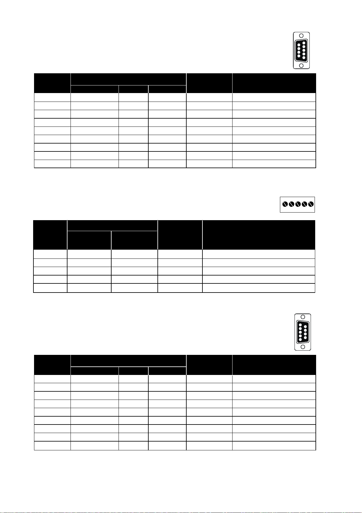
Ethernet 10Base-T Connection (RJ-45 connector)
Media Dependent Interface (MDI)
Contact Signal Name Direction** Description
1 TD+ Out Transmitted Data
2 TD– Out Transmitted Data
3 RD+ In Received Data
4NC
5NC
6 RD– In Received Data
7NC
8NC
** Direction relative ED-20
NC Not connected
CAT 5 cable is recomended.
Unshielded (UTP) or shielded (STP) cables might be used.
Page 10
Pin Signal Name*
Direction** Description
Number Description V.24 RS-232C
1 DCD 109 CF – Data Carrier Detect, NC
2 RD 104 BB Out Received Data
3 TD 103 BA In Transmitted Data
4 DTR 108.2 CD – Data Terminal Ready, NC
5 SG 102 AB In/Out Signal Ground
6 DSR 107 CC – Data Set Ready, NC
7 RTS 105 CA In Request to Send, NU
8 CTS 106 CB Out Clear to Send, NU
9 RI 125 CE – Ring Indicator, NC
Pin Signal Name*
Direction** Description
Number Description V.24 RS-232C
1 DCD 109 CF Out Data Carrier Detect
2 RD 104 BB Out Received Data
3 TD 103 BA In Transmitted Data
4 DTR 108.2 CD In Data Terminal Ready
5 SG 102 AB In/Out Signal Ground
6 DSR 107 CC Out Data Set Ready
7 RTS 105 CA In Request to Send
8 CTS 106 CB Out Clear to Send
9 RI 125 CE – Ring Indicator, NC
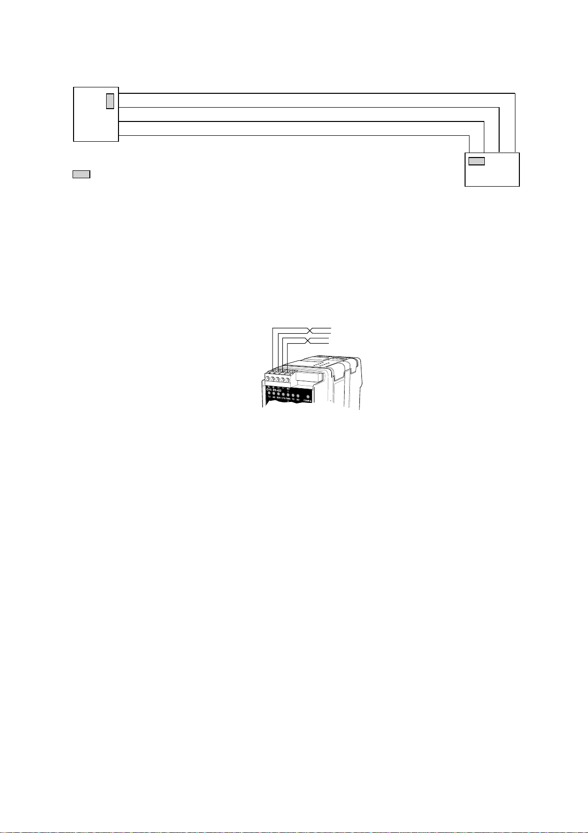
CH1: RS-422 Connections (Upper left screw terminal)
* Numbered right to left (front view). ** Direction relative ED-20.
Twisted pair cable is recommended
10 6609-2222
CH1: RS-232 Connections, DCE
* Functionality might differ from standard ** Direction relative ED-20
NC Not connected
CH2: RS-232 Connections, DCE
* Functionality might differ from standard ** Direction relative ED-20
NC Not connected NU Not used
1
2
3
4
5
6
7
8
9
5
4
3
2
1
9
8
7
6
543
2
1
Terminal
Signal Name*
Number
Marked on According
ED-20 to Standard
Direction** Description
1 SG – – Not connected
2 T– B Out RS-422 4-wire Transmitter
3 T+ A Out RS-422 4-wire Transmitter
4 R– B’ In RS-422 4-wire Receiver
5 R+ A’ In RS-422 4-wire Receiver
Page 11
116609-2222
ED-20
(ED-20)
=Termination
4-wire termination
R+
R–
T+
T–
R– R+ T– T+
RS-422 general advice
4-wire
Twisted pair cable is recommended
Termination recommendations
The RS-422 line must be terminated. The receiver on each side shall be terminated.
RS-422 connection pins can be differently named.For some brands the T+ corresponds
to A, but other brands might use some other naming convention.
If a unit does not work it can help to swap A and B.
Page 12

12 6609-2222
6.3. Settings
6.3.1. Channel 1 serial interface
Settings of the Ethernet Router are made with DIP switches and with ED-Tool for ED-20
(Windows based configuration software).
6.3.1.1. DIP Switch Settings
DIP-switches are accessible under the lid on top of the unit. DIP-switches are used to
set-up the serial port.
Warning!
Prevent damage to internal electronics from electrostatic discharges (ESD) by
discharging your body to a grounding point (e.g. use of wrist strap), before the
lid on top of the unit is removed.
Warning! Do not open connected equipment.
Prevent access to hazardous voltages by disconnecting the unit from AC/DC
mains supply and all other electrical connections.
NOTE! Always reboot the unit after any changes
of the DIP-switches has been made.
!
!
Page 13

136609-2222
Termination and fail safe
(4-wire) Channel 1
Port type
Channel 1
ON
12345678
S1
RS-422
ON
12345678
S1
RS-232
Factory settings
ON
12345678
S2
Not used
ON
12345678
S1
Channel 1
ON
12345678
S1
Termination
and fail safe off
ON
12345678
S1
120 Ω termination
between R+ and R–
Terminal open interpreted
as Mark (1)
IC2
Not used with RS-232
S2: 1–8
S1: 1–8
Page 14

14 6609-2222
6.3.2 Configuration ports
The unit have two configuration ports, locally via the RS-232 port (Channel 2) and
remotely via Ethernet (Telnet port).
6.3.3 LED indicators
Indicators (LED) Power (PWR)
Link (NET)
Serial status,TD, RD, RTS and CTS
Configuration
LED Status Indication of
PWR ON Power OK
OFF No Ethernet link
NET ON Good Ethernet link
Flash* Ethernet data is transmitted or received, traffic indication
CONFIG ON Configuration mode (unit has been reconfigured,
new parameters not valid until a reboot has been made)
OFF Application mode (or during start up of configuration mode)
Serial specific indication of
RS-232 selected RS-422 selected**
TD ON Received data on serial port Received data on serial port
RD ON Transmitted data on serial port Transmitted data on serial port
RTS** OFF Request To Send deactivated Always OFF
ON Request To Send activated
CTS** OFF Clear To Send deactivated Shall always be OFF
ON Clear To Send activated Reconfigure flow control
* Constant flashing at constant rate may indicate a speed mismatch
** Only on channel 1
Page 15

156609-2222
6.4 MAC address
The MAC address of the unit can be found on the product label “00 30 56 F” + last 5
digits on IC2 see figure in section 6.3 Switch settings on page 13. Example: Label on IC2
“SC12 RTOS 0092C2” this will give the unit MAC address “00 30 56 F0 92 C2”
The MAC address can also be find out with the DOS command “ARP –a”. (Perform the
“PING” command with the ED-20 local IP address before the ARP command.)
6.5 Installation of ED-Tool for ED-20
This section describes the installation of ED-Tool for ED-20.
System Requirements:
To install and run the ED-Tool for ED-20 program following requirements are needed.
Minimum:
… 386, 486 or Pentium‚ Processor-based personal computer
… Microsoft‚ Windows‚ 95/98/Me, Windows NT 3.51/4.0‚
or Windows 2000‚ Windows XP, compatible OS
… 16 MB of RAM for Windows 95/98/Me systems
… 24 MB of RAM for Windows NT systems
… 32 MB of RAM for Windows 2000/XP systems
… CD-ROM drive
… 8 MB of space on hard drive
… Serial and/or Ethernet network connections
… Internet Explorer 5.0 or higher
Recommended:
… Pentium processor-based personal computer
… 32 MB of RAM
Installation:
To install ED-Tool for ED-20
… Insert the ED-Tool for ED-20 CD-ROM into the CD-ROM drive
… Locate the ‘setup.exe’ file on the ED-Tool for ED-20 CD-ROM
… Run the ‘setup.exe’ and follow the instructions
Page 16

16 6609-2222
7. Functional description
The ED-20 can be in either configuration mode or in application mode. Normally the
ED-20 is in application mode, where the serial-to-network data transfer is enabled and all
configuration settings are readable.
Change of configuration parameters are done in ED-20 configuration mode. Configurable
parameters are listed in chapter 8.2.
7.1 Application mode
In application mode the ED-20 transfers data between the serial interface (CH1) and the
network interface (10Base-T). At the network interface data is transferred using the
TCP/IP protocol suit. At the serial interface data is transferred using PPP.
7.1.1 About PPP
PPP (the Point to Point Protocol) is a mechanism for creating and running TCP/IP over
a serial link – a direct serial connection or a link made using one of following:
Westermo analogue PSTN-, Leased-line-, ISDN-, GSM-, Fibre- or Short-haul modem.
Other computers can connect via the ED-20 and communicate over the PPP link using
FTP,Telnet,Web, etc. in the same manner as with an Ethernet TCP/IP link. One major
difference between a PPP and an Ethernet connection is of course the speed.A standard
Ethernet connection operates at 10 Mbit/100 Mbit maximum theoretical throughput,
whereas an analogue modem operates at speeds up to 56 kbit.
PPP is strictly a peer to peer protocol; there is no difference between the machine that
dials in and the machine that is dialed into. However, it is still useful to think in terms of
servers and clients.When you dial into a site to establish a PPP connection, you are a
considered the client.The machine to which you connect is considered the server.
Authentication is provided with the protocols PAP or CHAP.
7.1.2 Network interfaces
ED-20 has two network interfaces, Ethernet and PPP, so the unit can forward IP-packets
between these interfaces.
7.1.2.1 Ethernet interface
This interface is a part of the local network and the ‘Local IP Address’* and ‘Subnet Mask’
must be set to the right ‘Network ID’
7.1.2.2 PPP Network interface
The PPP connection can be established over PSTN, Leased Line or private lines.
ED-20 can act as a PPP Server, PPP Client or both.These functions is set on the ‘Modem
settings’ tab in ED-Tool for ED-20. See application example in chapter 9.
* The IP address must be compliant to the attached network. Ask the network administrator when in doubt.
Page 17

176609-2222
Connections can be established in several ways depending on the application:
• Standard PPP dial-up networking tool.
• ‘Connect’ command on CH2: or via TELNET
• Using the ‘Brouter’ function.
7.1.2.3 Brouter function
The Brouter function will establish a dial-up connection when valid outbound IP address
(Defined on the tab ‘Brouter Settings’ in ED-Tool for Ed-20) is sent to the ED-20.
See application example on page 34.
The connection will be open until one of following is true:
• There is no traffic during and the ‘Idle Time’ parameter is set to a value greater
than zero.
e.g. Idle Time is set to 600s and there is no traffic sent to the ED-20
for more than 10 minutes.
• ‘Close’ command on CH2: or via TELNET
Note! It may be wise to use the Firewall function while the Brouter function being used
to reduce the traffic over the PPP link.
7.1.2.4 Firewall function
The Firewall function can be set-up to allow or block certain IP Addresses through the
ED-20. See application example on page 34.
7.1.2.5 Proxy ARP function
The Proxy ARP function can be activated and used to divide an existing network into
several networks and keep the original IP address settings. I.e the networks would appear
to be one single network instead of multiple networks connected to each other.This will
allow the connected equipment to communicate to each other without using gateways
and is a benefit when attaching equipment not supporting gateway functionality.
7.2 Configuration mode
Local or remote configuration is managed by ED-Tool for ED-20.
ED-Tool for ED-20 is a Windows based set-up program which provides easy configuration.
Configuration is possible locally by using serial connection and remote using network
(telnet) connection. Configuration mode will be entered automatically by ED-Tool for
ED-20. ’Config ’ LED will lit when ED-20 is in configuration mode. (The unit is not in
configuration mode until the ‘Write config’ button been pushed.)
The unit will be in configuration mode until a reboot is made.
First time configure: ED-20 is shipped with IP-address 169.254.100.100.
Please make sure that 169.254.100.100 is compliant to your network, before ED-20 is
connected. Otherwise use serial interface to locally set a valid IP address compliant with
the network in use and not chosen arbitrarily, ask your network administrator when in
doubt.
Page 18

18 6609-2222
8. Configuration
Before read, write or reboot can be made, Select type of connection:
• Network
• Serial com port must be selected from menu ‘Tools – Serial COM Port’
8.1 Configuration by ED-Tool for ED-20
This section describes the configuration of the ED-20 with the software ED-Tool
for ED-20.
Program Start:
To start ED-Tool for ED-20
• Locate ED-Tool for ED-20 under Program/Westermo on the Start-Menu.
• Click on the ED-Tool for ED-20 icon
When the ED-Tool for ED-20 has been successful opened the user is presented with an
empty configuration screen.The user can now get an existing configuration by reading
the configuration from an ED-20, create a new file from default values or by opening a
stored configuration file.
After all the parameters are set the user can write the configuration to the ED-20.
Typical configuration procedures:
• Read configuration from an ED-20
• Change some parameters
• Write configuration to the ED-20
• Reboot
• Done
or
• Read configuration from a file
• (Change some parameters)
• Write configuration to the ED-20
• Reboot
• Done
or
• Set parameters
• Write configuration to ED-20
• Reboot
• Done
or
• Set parameters
• Save configuration to a file
• Done
Page 19

196609-2222
8.1.1 ED-Tool for ED-20 commands
This section describes the ED-Tool for ED-20 commands.
The commands are described by there use.
Details about allowed values and default values is described is section 8.2.
8.1.1.1 General commands
1 Selects type of connection, Serial or over the Network.
If ‘Serial’ is selected, use the “Tools menu – Serial COM port” to
select which of COM1:, COM2:, COM3:, or COM4: your serial
cable is connected to.
2 Read Config Reads configuration from the ED-20.
3 Write Config Writes configuration to the ED-20.
Note! ED-20 must be rebooted before any new configuration
is activated.
4 Reboot Reboots the ED-20.
8.1.1.2 Serial Interface – Channel 1 specific commands
Communication
5 Data Rate Selects Data Rate for serial communication, ED-20 – Modem.
6 Flow Control Selects if flow control is used or not.
Note! All interconnecting wires are required between the ED-20
and the attached modem.Flow control must be set to none
when using RS-422.
1
2
3
4
5
6
57600
RTS/CTS
Page 20
20 6609-2222
PSTN
1
2
3
4
5
6
7
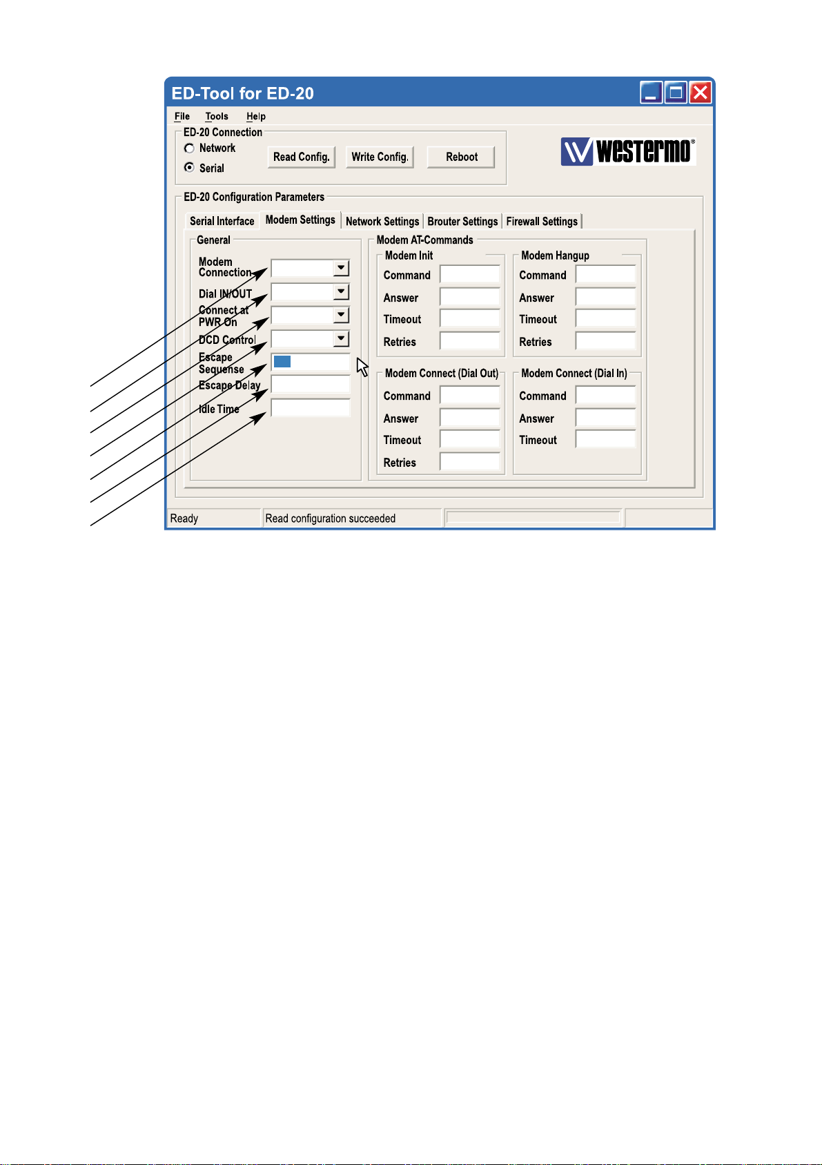
8.1.1.3 Modem Settings
General
1 Modem Select Type of connection, PSTN or LL.
Connection • Use PSTN for dial-up connections, e.g. Phone modem, GSM
modem or ISDN adapter.
• Use LL for fixed connections, e.g. LeasedLine-, Radio-, Fibreor any Short-haul- modem.
2 Dial IN/OUT Select if the ED-20 shall act as a PPP Server, PPP Client or both.
When the unit is set to be a server, it will answer incoming calls.
3 Connect at Select if the ED-20 shall initiate a connection at power on
PWR On with the Modem Connect (Dial Out) command.
4 DCD Control Select if the ED-20 shall disconnect the PPP link at modem DCD
loss.
Note! All interconnecting wires are required between the ED-20
and the attached modem.
5 Escape Set the modem escape sequence wich switches the modem into
Sequence command mode. Not used for Leased Line mode. Usually ‘+++’.
6 Escape Delay Set the delay time in seconds after the escape sequence before
any other command.
7 Idle Time Set the idle time in seconds, after which the PPP server closes the
connection if no data being sent.
DIAL IN/OUT
NO
NO
+++
2
600
AT&F&DOSO
OK
3
1
ATDS=0
CONNECT
60 0
1
ATH
OK
3
1
RING
ATA
Page 21
216609-2222
AT&F&DOSO
OK
3
1
ATH
OK
3
ATDS=0
CONNECT
60 0
1
RING
ATA
1
8
9
10
11
12
13
14
15
16
17
18
19
20
21
22
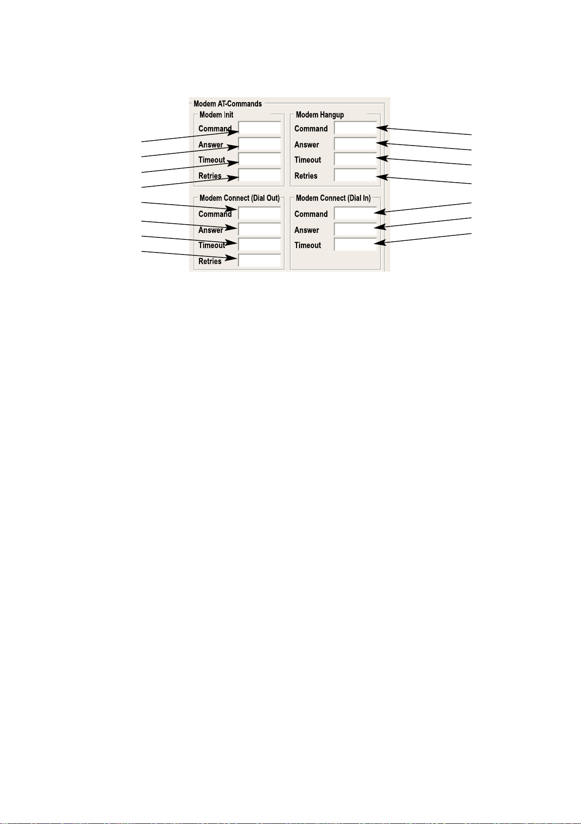
Modem Init
8 Command Set the modem init string.
9 Answer Set the expected answer from the modem on the command
string. Note! Modem result codes must be enabled.
10 Timeout Set the timeout in seconds for how long the ED-20 shall wait
for the answer string.
11 Retries Set the number of retries before the modem init fails.
Modem Hangup
12 Command Set the modem hangup string.
13 Answer Set the expected answer from the modem on the command
string. Note! Modem result codes must be enabled.
14 Timeout Set the timeout in seconds for how long the ED-20 shall wait for
the answer string.
15 Retries Set the number of retries before the modem hangup fails.
Modem Connect (Dial Out)
16 Command Set the modem connect string.
17 Answer Set the expected answer from the modem on the command.
string. Note! Modem result codes must be enabled.
18 Timeout Set the timeout in seconds for how long the ED-20 shall wait for
the answer string.
19 Retries Set the number of retries before the modem connect fails.
Modem Connect (Dial In)
20 Command Set the modem connect string.
21 Answer Set the expected answer from the modem on the command.
22 Timeout Set the timeout in seconds for how long the ED-20 shall wait for
the answer string.
Modem AT-Commands
Refer to the user guide or installation manual to the attached modem.
Page 22

22 6609-2222
1
2
3
4
5
6
7
8
9
8.1.1.4 Network Settings
Login
1 Authentication Select if authentication shall be used or not.
2 Username Set the login username.
This is also used for Telnet sessions (Network configuration).
3 Password Set the login password
This is also used for Telnet sessions (Network configuration).
PPP Network Interface*
4 Local IP Set the Server IP address.
5 Remote Address Set the Client IP address.
6 Subnet Mask Set the Subnet mask.
Ethernet Interface*
7 Local IP Address Set the Local IP address i.e. the address of the ED-20.
8 Subnet Mask Set the Subnet mask.
9 Proxy Arp Set the Proxy ARP funktion Off/On.
* The IP address must be compliant to the attached network.Ask the network administrator when in doubt.
Page 23

236609-2222
1
2
3
4
5
6
8.1.1.5 Brouter Settings
Brouter Mode
1 Off / On Disables or enables the Brouter mode.
See 8.2.4
Brouter Settings
2 IP Address Set the target IP address that shall initiate a connection.
3 Connect Set the Connect message that shall be sent to the attached
Message modem. E.g. ATDnnnnnn
4 Add >> Adds the values IP Address and Connect message to the
brouter entry list
5 Remove ... Remove marked entry from entry list.
6 Brouter Entry List
Displays the Brouter entry’s: IP Address, Connect message.
Up to 32 entry’s can be added.
• To Add an entry: Fill in the field IP Address and the field Connect message, Press add.
• To Edit an entry: Double click the entry that shall be edited, Edit the values in the fields
to the left, Press add.
• To Remove an entry: Click the entry that shall be removed, Press remove.
. . .
Page 24

24 6609-2222
. . .
1
2
3
4
5
8.1.1.6 Firewall Settings
Firewall Mode
1 Off / Pass / Block Disables or enables the Firewall mode and selects if the firewall
shall work in Block or Pass mode. See 8.2.5
Firewall Settings
2 IP Address Set the source and destination IP addresses that shall be allowed
to pass through the ED-20, or set the source or destination IP
addresses that shall be blocked from passing through the ED-20.
3 Add>> Adds the values IP Address and Connect message to the
Firewall entry list.
4 Remove ... Remove marked entry from entry list.
5 Firewall Entry List.
Displays the Firewall entry’s: IP Address.
Up to 32 entry’s can be added.
Page 25

256609-2222
8.2 Configurable parameters
8.2.1 Serial interface
Communication
Data Rate
The data rate can be set from 1 200 bit/s to 115.2 kbit/s.
Allowed values:
1 200, 2 400, 4 800, 7 200, 9 600, 14 400, 16 000, 19 200, 38 400, 56 000, 57 600
and 115 200 bit/s.
Default: 57 600 bit/s.
Flow Control
Flow control can be chosen between NONE or RTS/CTS.
If the RTS/CTS being used then the cable must have all interconnecting wires
between the ED-20 and the modem connected and the modem shall have the flow
control enabled.
Note! When RS-422 is selected for channel 1, set flow control to NONE.
Allowed values: None, RTS/CTS
Default: RTS/CTS.
8.2.2 Modem settings
General
The general settings is used to set the fundamental modes of the ED-20.
Modem Connection
Type of modem connection can be selected between PSTN (Public Switched
Telephone Network) and LL (Leased Line).
PSTN shall be used for dial-up/dial-in connections with PSTN, ISDN or GSM modem.
LL shall be used in fixed connections, e.g. short-haul-, fibre-, LL-modem.
In LL mode the unit will not use any modem AT-commands, Modem escape sequence,
AT-commands and the Brouter function will be disabled.The modem will be handled
as a transparent connection.
Allowed values: LL, PSTN
Default: PSTN.
Communication
General
Page 26

26 6609-2222
Dial IN/OUT
Select the operating mode of the ED-20.
-Dial IN,
The unit will act as an PPP Server and only accept incoming calls.
Modem Connect (Dial OUT) and the Brouter function will be disabled.
-Dial IN/OUT,
The unit will act both as an PPP Server and an PPP Client.
When an incoming call is detected then the PPP Client is disabled.
–Dial OUT,
The unit will act as an PPP Client and not accept incoming calls.
Modem Connect (Dial IN) and the function Connect at PWR on will be disabled.
Allowed values: Dial IN, Dial IN/OUT, Dial OUT
Default: Dial IN/OUT
Connect at PWR on
Selects if the ED-20 shall establish a connection at Power on or not.
In PSTN mode the ED-20 will dial up using the command string defined in Modem
Connect (Dial OUT) and when the modem link is ready, Establish the PPP link.
In LL Mode the ED-20 will establish the PPP link.
This function is disabled in Dial IN mode.
Allowed values: NO,YES
Default: NO
DCD Control
When the signal DCD is lost the ED-20 will close the PPP link and when PSTN mode
is selected the AT commands for Modem hangup and Modem init will be sent to the
modem.
This function requires a special cable.
Allowed values: NO,YES
Default: NO
TD-XX
With 9-pos. female
DCE connection
9-pos. female 9-pos. female 25-pos. female 9-pos. female
ED-20
With 9-pos. female
DCE connection
2
3
8
7
4
5
1
3
2
7
8
6
5
4
TD-XX
With 25-pos. female
DCE connection
ED-20
With 9-pos. female
DCE connection
3
2
5
4
20
20
7
8
3
2
7
8
6
5
4
Escape Sequence
When communication is established with another modem it is still possible to reach
the command mode by sending an escape sequence to the modem.
Note! Refer to the user guide or installation manual to the attached modem.
Default: +++
Page 27

276609-2222
Escape Delay
Define the delay time in seconds after the escape sequence been sent until the next
AT-command will be sent.
Allowed values, 1 to 9999
If this value is set to zero, the unit will do nothing but wait!
Default: 2 (seconds)
Idle Time
If no data is being sent over the PPP link the ED-20 will close the connection.
Define the time in seconds.
Allowed values, 0, 1 to 9999
Default: 0 (function disabled)
Modem AT-Commands
Commands used in PSTN mode for controlling the behaviour of the attached
modem.
Note! Refer to the user guide or installation manual to the attached modem.
Modem Init
Command
Init string that will be sent to the modem.
Default:AT&F&D0S0=0&K3+MS=V34;&W
Answer
Expected answer from the modem on the sent command.
Allowed string length: 25 characters.
Default: OK
Timeout
Define the time in seconds between the sent command and the expected answer
before the command have failed.
Allowed values: 0 to 9999
Default: 3
Retries
Define the number of retries in case if a failed command.
Allowed values: 0 to 9999
Default: 1
Modem Hangup
Command
Hangup string that will be sent to the modem.
Allowed string length: 25 characters.
Default:ATH
Modem AT-Commands
Modem Init
Modem Hangup
Page 28

28 6609-2222
Answer
Expected answer from the modem on the sent command.
Default: OK
Timeout
Define the time in seconds between the sent command and the expected answer
before the command have failed.
Allowed values: 0 to 9999
Default: 3
Retries
Define the number of retries in case if a failed command.
Allowed values: 0 to 9999
Default: 1
Modem Connect (Dial Out)
Command
Dial out string that will be sent to the modem.
Allowed string length: 25 characters
Default:ATDS=0 (dials the stored number in location 0, stored with AT&Z command)
Answer
Expected answer from the modem on the sent command.
Default: CONNECT
Timeout
Define the time in seconds between the sent command and the expected answer
before the command have failed.
Allowed values: 0 to 9999
Default: 60
Retries
Define the number of retries in case if a failed command.
Allowed values: 0 to 9999
Default: 1
Modem Connect (Dial In)
Command
Dial in string that will be sent from the modem on an incoming call.
Allowed string length: 25 characters
Default: RING
Answer
Command that will answer the incoming call.
Default:ATA
Modem Connect (Dial Out)
Modem Connect (Dial In)
Page 29

296609-2222
Timeout
Define the time in seconds, For how long time the ED-20 will accept incoming calls
from power-up. Normally not used, leave as is.
Allowed values: 0-9999
Default: 0
8.2.3 Network Settings
Login
The login username and password is used on the dial-in connection and when the
ED-20 is configured with ED-Tool for ED-20 over a network connection.
Authentication
Select if authentication shall be used over the PPP link or not.
Authentication can be used with either the PAP (Password Authentication Protocol)
or CHAP protocols (Challenge Handshake Authentication Protocol)
If a invalid Username or password is entered the ED-20 will disconnect the PPP link
and cause the modem to disconnect.
Allowed values: NONE, PAP, CHAP
Default: NONE
Username
Allowed string length: 1 – 19 characters.
Allowed characters: ‘0’ to ‘9’, ‘a’ to ‘z’ lower case.
Default: ed20
Password
Allowed string length: 1 – 19 characters.
Allowed characters: ‘0’ to ‘9’, ‘a’ to ‘z’ lower case.
Default: ed20
PPP Network Interface
These values is used when the ED-20 is in Server mode.
The server will provide the IP addresses for the PPP link.
Note! When connecting to a private remote network via the ED-20 using Windows
network connection wizard, Always Obtain an IP address automatically
Local IP*
When the ED-20 is in server mode, this will be the Servers IP address on the PPP
link
Note! The Network ID must be different than the Network ID on the remote net-
work and the Network ID locally.
Allowed values: Should be in decimal dotted notation in one off the following ranges:
1.0.0.0 126.0.0.0
128.1.0.0 191.255.0.0
192.0.1.0 223.255.255.0
Default: 169.254.200.100
Login
PPP Network Interface
* The IP address must be compliant to the attached network.Ask the network administrator when in doubt.
Page 30

30 6609-2222
Remote address*
When the ED-20 is in server mode, this will be the Clients IP address on the PPP link
Allowed values: Should be in decimal dotted notation And have the same
Network ID as Local IP and different then Local IP
Default: 169.254.200.101
Subnet Mask*
Set a valid subnet mask in decimal dotted notation.
Default: 255.255.255.0
Ethernet Interface
Local IP Address*
This is the address of the router and this address shall be used as default gateway in
the units that will use the ED-20 as a gateway.
Set the local IP address in the rage of the Network ID.
Note! The Network ID must be different than the Network ID on the PPP link
and the Network ID on the other network.
Allowed values: Should be in decimal dotted notation in one off the following ranges:
1.0.0.0 126.0.0.0
128.1.0.0 191.255.0.0
192.0.1.0 223.255.255.0
Default: 169.254.100.100
Subnet Mask*
Set a valid subnet mask in decimal dotted notation.
Default: 255.255.255.0
Prox Arp
Enable or disable the Proxy ARP function with the radio buttons.
Default: OFF
8.2.4 Brouter settings
The brouter function will initiate outgoing connections.
This function is only available in PSTN + Dial Out mode
(Refer to section 8.2.2 – General – Modem settings and Dial IN/OUT.)
When a IP packet sent to the ED-20 have a IP Address that match a IP Address in the
entry list, the ED-20 will send the connect message to the attached modem.This will
result in an connection to another location and establishment of a PPP link.
Note! Since the ED-20 and the attached modems need some time to establish a modem
connection and a PPP link, The IP packets sent before the PPP link is ready may be
lost depending of the application used.
* The IP address must be compliant to the attached network.Ask the network administrator when in doubt.
Ethernet Interface
Page 31

316609-2222
Brouter Mode
Enable or disable the brouter function with the radio buttons.
Note! The brouter function can only be enabled when the ED-20 is allowed to act
as a PPP client. (Refer to section 8.2.2 – General – Dial IN/OUT.)
Default: Off
Brouter Settings
IP Address
Allowed values: Should be in decimal dotted notation and in another Network ID
than the Local IP Address of the ED-20.
(Refer to section 8.2.3 – Ethernet Interface – Local IP Address)
Connect Message
This message will establish the modem connection.
Allowed values: Is decided by the attached modem.
Note! Refer to the user guide or installation manual to the attached modem.
8.2.5 Firewall settings
The firewall function will allow the network administrator to control the network access
and limit the traffic on the PPP link. It’s possible to accomplish this in two modes.
- Pass,Will only allow traffic where the source and destination IP address is present in
the entry list.
- Block,Will block traffic where either source or destination is present in the entry list.
See application exampes on page 34.
Firewall Mode
Disables or enables the Firewall mode with the radio buttons.
And selects if the firewall shall work in Block or Pass mode.
Default: Off
Firewall Settings
IP Address
Allowed values: Should be in decimal dotted notation.
Brouter Mode
Brouter Settings
Firewall Mode
Firewall Settings
Page 32
32 6609-2222
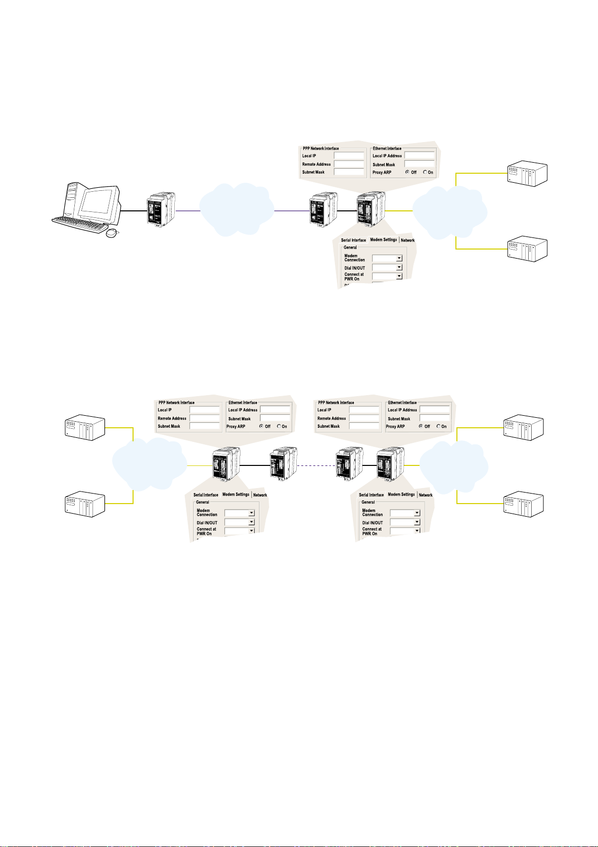
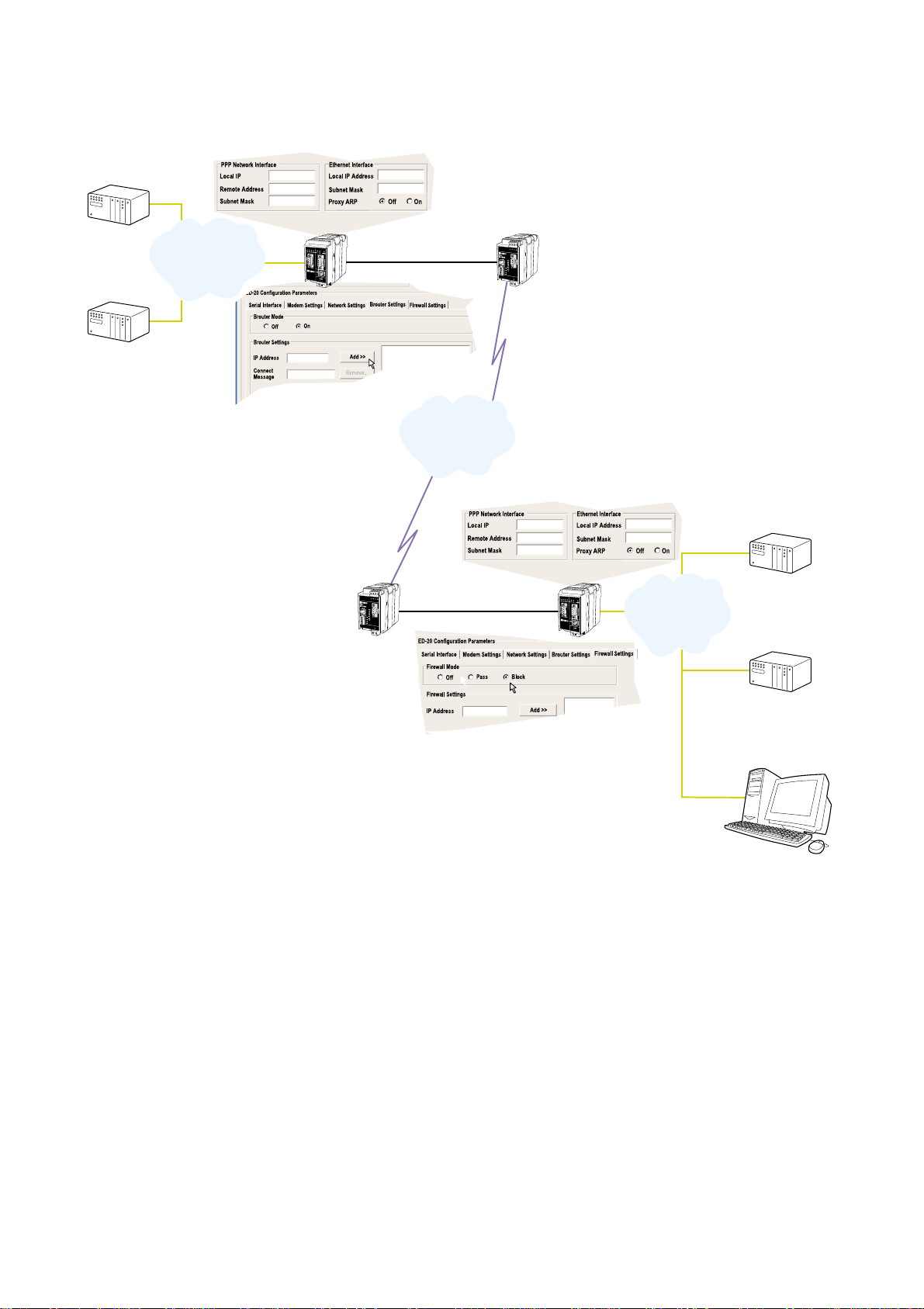
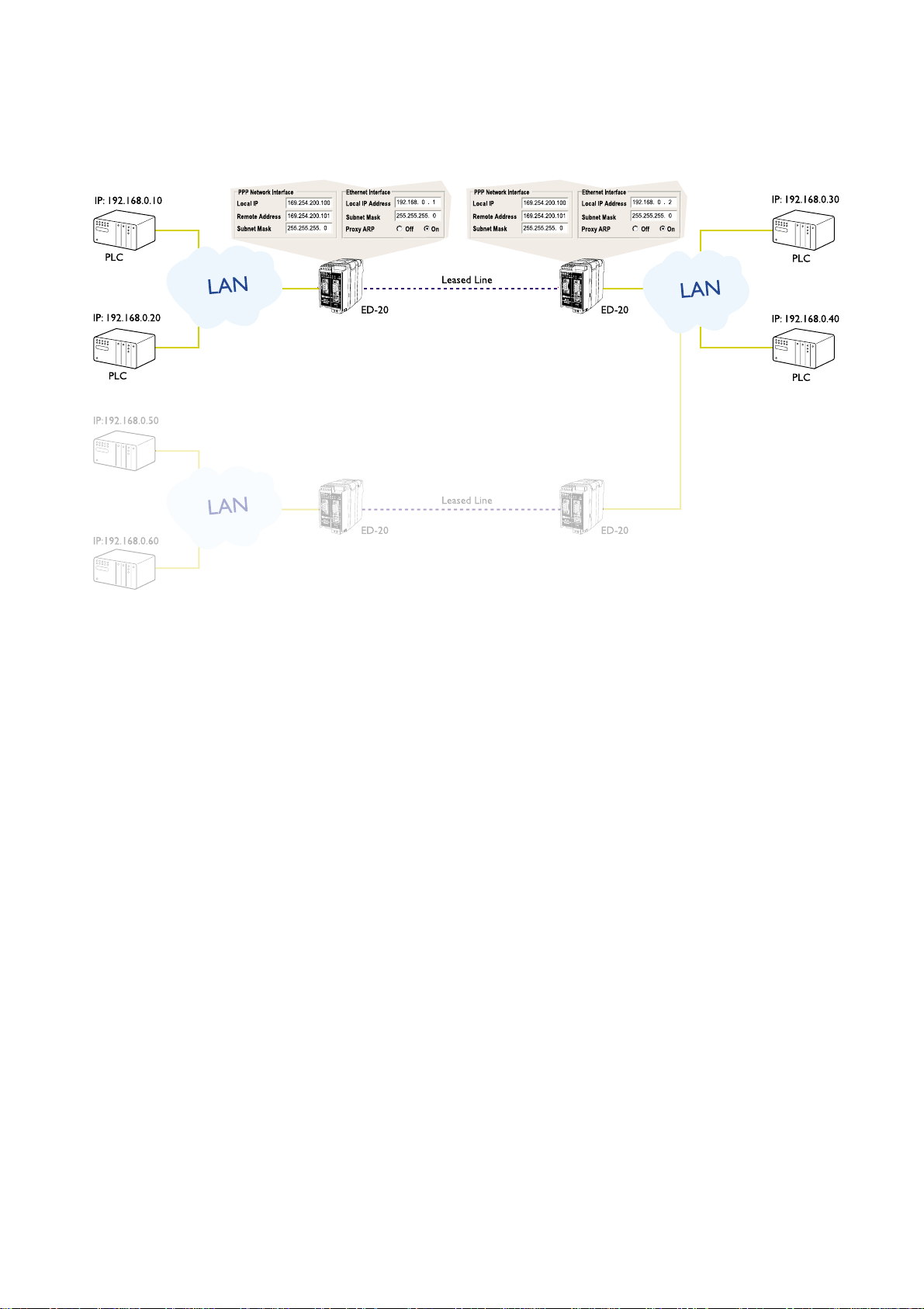
9. Application examples
Example of application with IP address settings.
Remote connection – LAN (Dial In)
LAN – LAN (Leased Line)
169.254.200.100
169.254.200.101
255.255.255. 0
169.254.100.100
255.255.255. 0
DIAL IN
PSTN
NO
NO
PSTN
LAN
PLC
PLC
ED-20
TD-33
Remote connection
TD-33
IP: 169.254.100.101
GW: 169.254.100.100
IP: 169.254.100.102
GW: 169.254.100.100
169.254.200.100
169.254.200.101
255.255.255. 0
169.254.100.100
255.255.255. 0
169.254.200.100
169.254.200.101
255.255.255. 0
169.254.100.100
255.255.255. 0
+++
DIAL IN/OUT
L.L
NO
NO
2
+++
DIAL IN/OUT
L.L
YES
NO
2
LAN
LAN
PLC
PLC
PLC
PLC
ED-20
TD-34
Leased Line
E
D
2
0
P
P
P
R
O
U
T
E
R
S
e
r
i
a
l
I
n
t
e
r
f
a
c
e
ED-20
E
D
2
0
P
P
P
R
O
U
T
E
R
S
e
r
i
a
l
I
n
t
e
r
f
a
c
e
TD-34
IP: 179.254.100.101
GW: 179.254.100.100
IP: 179.254.100.102
GW: 179.254.100.100
IP: 169.254.100.101
GW: 169.254.100.100
IP: 169.254.100.102
GW: 169.254.100.100
Page 33
336609-2222
LAN – LAN (PSTN, GSM)
+++
DIAL IN/OUT
PSTN
NO
NO
2
600
+++
DIAL IN/OUT
PSTN
NO
NO
2
600
PSTN
LAN
PLC
PLC
PLC
PLC
ED-20
GD-01
ED-20
TD-33/V.90
ID-90/V.90
1
2
3
4
9
8
7
6
5
LAN
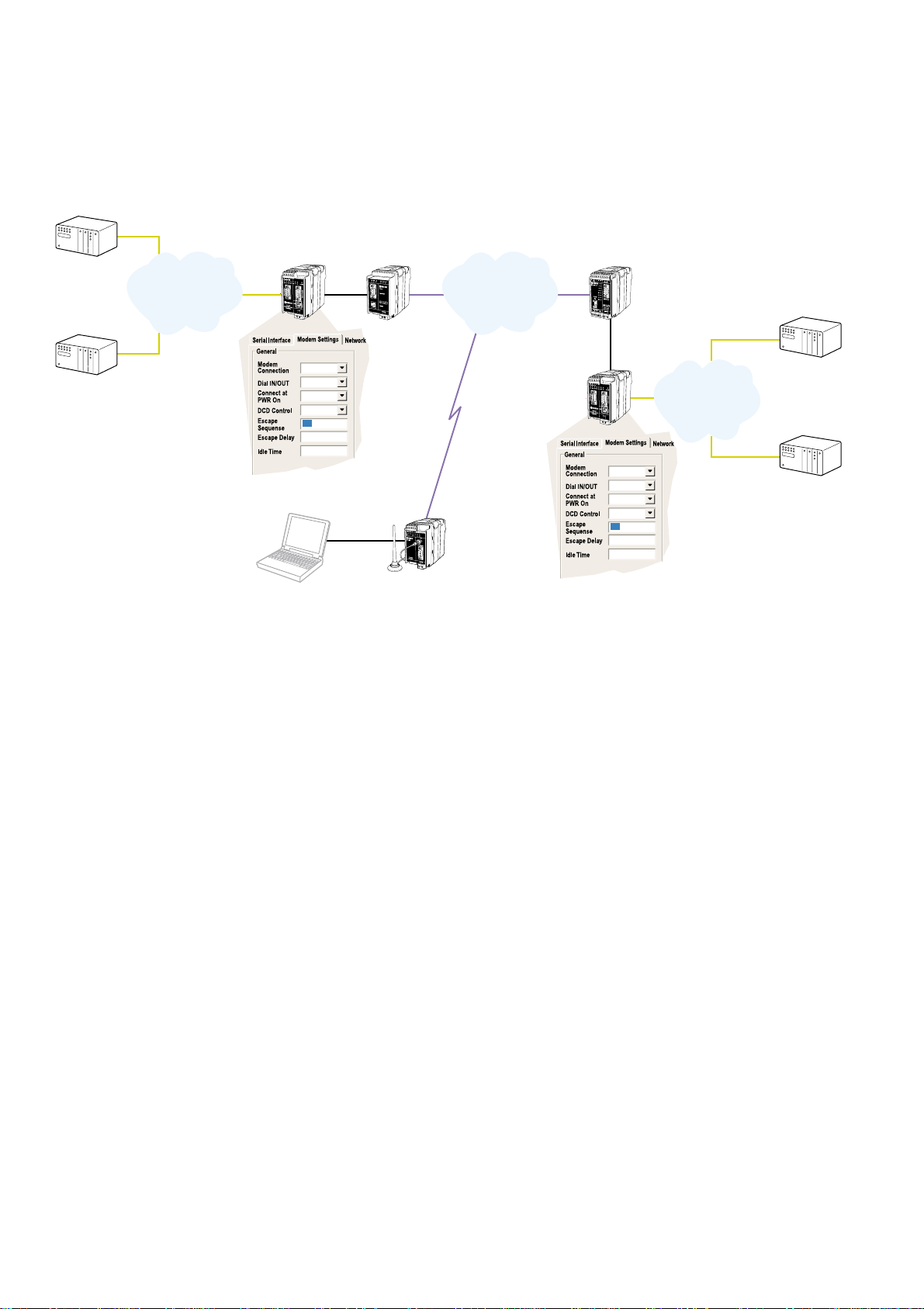
Page 34
34 6609-2222
LAN – LAN (PSTN, Brouter, Firewall)
169.254.100.101
ATDnnnnnn
PLC
TD-34
PLC
PLC
ED-20
TD-34
IP: 179.254.100.101
GW: 179.254.100.100
IP: 179.254.100.102
GW: 179.254.100.100
IP: 169.254.100.101
GW: 169.254.100.100
ED-20
169.254.100.135
. . .
PSTN
169.254.100.101 ATDnnnnnn
LAN
PLC
IP: 169.254.100.102
GW: 169.254.100.100
IP: 169.254.100.135
LAN
169.254.200.100
169.254.200.101
255.255.255. 0
179.254.100.100
255.255.255. 0
169.254.200.100
169.254.200.101
255.255.255. 0
179.254.100.100
255.255.255. 0
E
D
2
0
P
P
P
R
O
U
T
E
R
S
e
r
i
a
l
I
n
t
e
r
f
a
c
e
E
D
2
0
P
P
P
R
O
U
T
E
R
S
e
r
i
a
l
I
n
t
e
r
f
a
c
e
Page 35
356609-2222
LAN – LAN (LL, Brouter, Firewall)
Page 36

T04-0194 • 6609-2222 04.05 Mälartryck AB, Eskilstuna, Sweden
Westermo Teleindustri AB • SE-640 40 Stora Sundby, Sweden
Phone +46 16 42 80 00 Fax +46 16 42 80 01
E-mail: info@westermo.se
Westermo Web site: www.westermo.com
Westermo Teleindustri AB have distributors in several
countries, contact us for further information.
Westermo Data Communications Ltd
Unit 14 Talisman Business Centre • Duncan Road
Park Gate, Southampton • SO31 7GA
Phone: +44(0)1489 580 585 • Fax.:+44(0)1489 580586
E-Mail: sales@westermo.co.uk
Westermo Data Communications GmbH
Goethestraße 67, 68753 Waghäusel
Tel.: +49(0)7254-95400-0 • Fax.:+49(0)7254-95400-9
E-Mail: info@westermo.de
Westermo Data Communications S.A.R.L.
9 Chemin de Chilly 91160 CHAMPLAN
Tél : +33 1 69 10 21 00 • Fax : +33 1 69 10 21 01
E-mail : infos@westermo.fr
Subsidiaries
 Loading...