

Page 1

Industrial Ethernet adapter
– Serial Server (TCP)
INSTALLATION MANUAL
6609-2211
www.westermo.com
ED-10
TCP
©
Westermo Teleindustri AB • 2001 • REV. B
Galvanic
Isolation
Transient
Protection
Balanced
Transmission
CE
Approved
Page 2

Page 3

36609-2211
Contents
1. Introduction
.......................................................................................................................................................................... 4–5
2. Safety ............................................................................................................................................................................................................ 5
3. Specification ......................................................................................................................................................................... 6–7
4. Maintenance ................................................................................................................................................................................ 5
5. Installation ....................................................................................................................................................................................... 8
5.1 Mounting / Removal
............................................................................................................................... 8
5.2 Connections
............................................................................................................................................ 9–10
5.2.1 RS-422/485 general advice
............................................................................... 11–12
5.3 Configuration
............................................................................................................................................... 13
5.3.1 DIP switch settings
...................................................................................................... 13–14
5.3.2 LED's
............................................................................................................................................................ 15
6. Functional description ......................................................................................................................... 17–18
7. Configuration ........................................................................................................................................................................ 19
7.1 Configuration by ED-Tool
............................................................................................. 19–21
7.2 Configuration by terminal
............................................................................................ 22–24
7.2.1. Local configuration
.............................................................................................................. 24
7.2.2. Remote configuration
...................................................................................................... 24
7.3 Configurable parameters
............................................................................................... 25–26
7.3.1. Serial interface
........................................................................................................................... 27
7.3.2. Packing algorithm
.................................................................................................................. 28
7.3.3. Network interface
................................................................................................................. 29
7.3.4. Mode
.......................................................................................................................................................... 30
7.3.5. MAC address
................................................................................................................................. 30
7. Application examples ....................................................................................................................................... 31
Page 4
4 6609-2211
1. Introduction
The ED-10 TCP is an Industrial Ethernet Adapter acting as a serial server. The type of
serial interface is selectable between RS-232 and RS-422/485. The Ethernet interface is
10BASE-T and TCP/IP Protocols are implemented for network communication.
The ED-10 TCP provides a remote serial interface for a computer connected through a
TCP/IP network.
To complete the connection to the ED-10 TCP additional software need to be used in
the computer. Different solutions are possible, e.g.:
1. Telnet to the ED-10 TCP.
All keystrokes are transferred to the remote serial interface.
Any characters received at
the remote serial interface
are transferred to the
computer screen.
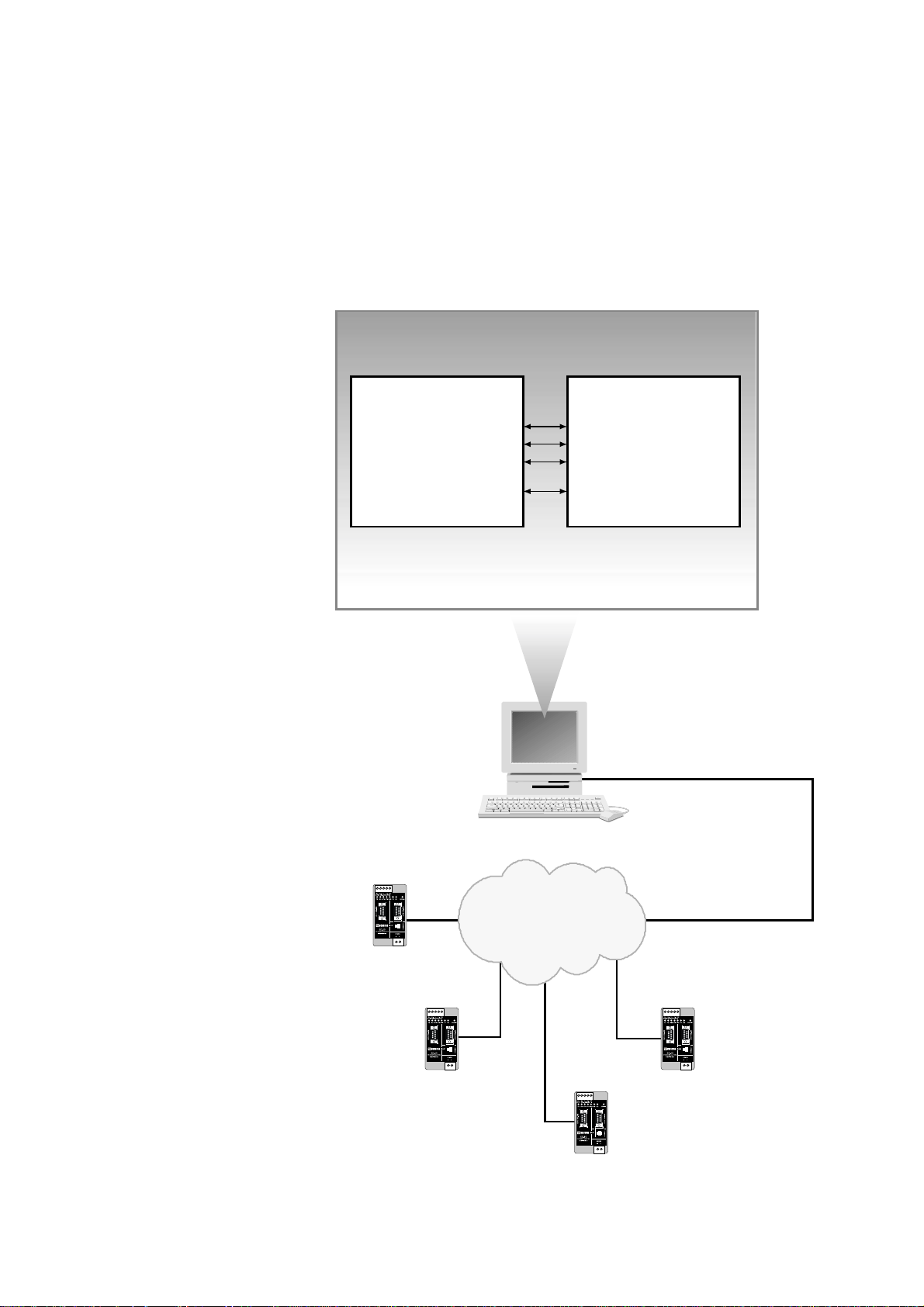
2. A COM port redirector
software can be used to
create up to 256 virtual
COM ports.
This software will redirect
data, originally sent to a
local COM port, to the remote serial interface of the ED-10 TCP. No change of computer application software is then necessary.
3. Customer written software can be used to
directly access the network interface (socket
compliant) of the ED-10 TCP.
A sample written in C++ can be found on
the CD ”\Software\Sample\sample.zip”
Network interface
Application software
Solution 2
Data to / from COM3
Data to / from COM4
Data to / from COM5
Data to / from COM256
COM port
redirector software
543
2
1
Network
ED-10 TCP
COM3
543
2
1
ED-10 TCP
COM4
543
2
1
ED-10 TCP
COM256
543
2
1
ED-10 TCP
COM5
ED-10 TCP Virtual COM ports connection
Page 5

56609-2211
The ED-10 TCP is ideal for use in the industrial environment.
It is housed in the Westermo DIN rail box and has a wide range power input, isolated
interfaces and enhanced surge/transient protection.
The ED-10 TCP is approved for Industrial EMC Immunity and Emission .
The ED-10 TCP uses the TCP/IP Internet Protocol Suit (TCP/IP) to transfer data over
the network.
TCP/IP is a set of protocols that enables communication across local and wide area networks and includes protocols such as TCP, UDP, IP , ARP, RARP, ICMP. Although not
all these protocols are needed for a network data transfer.
The ED-10 TCP uses TCP for remote configuration (configuration mode) and for the
serial server application.
The ED-10 TCP can be configured both remotely over the TCP/IP network and locally
via the RS-232 interface, making the unit very flexible.
Local or remote configuration is achieved either by using the ED-Tool Windows‚ software or by using a terminal programme (e.g. HyperTerminal for local configuration or
Telnet for remote configuration).
A DIP switch setting also allows the unit to be reset to factory default, if required.
2. Safety
General:
Before using this unit,read the manual completely and comply with information
on the unit,and make sure that you understand it fully.Check that your application does not exceed the safe operating specifications for this unit.
Before installation,maintenance or modification work:
Prevent damage to internal electronics from electrostatic discharges (ESD) by discharging your body to a grounding point (e.g.use of wrist strap).
Installation:
This unit is constructed for professional system use.It should be located in a
restricted access area,such as locked cabinet which can only be accessed by service personnel.
Sound installation practice, as defined by applicable local codes or regulations,shall
be followed in every instance in which such practice is applicable.
This unit is defined as class III equipment and shall be separated from hazardous
voltage by double or reinforced insulation.
All interfaces must only be connected to SELV or TNV-1 circuits.
!
!
!
Page 6

6 6609-2211
3. Specification
Network Interface 10BASE-T. IEEE std 802.3, 2000 Edition.
Data rate 10 Mbit/s, half duplex.
Mechanical RJ-45 Modular Jack (ISO/IEC 8877:1992),
Unshielded or shielded (UTP/STP).
Serial Interface 1 RS-232 or RS-422/485
Data rate 300–115 200 bit/s Full, half duplex or simplex.
Data format 7–8 Data Bits, Odd, Even or None Parity Bit,
1–2 Stop Bits (2 stop bits when no parity only)
Control signals* RTS, CTS, DSR, DCD, DTR
Termination** Termination and fail safe, on or off
Mechanical RS-232: 9-pin female D-sub.
RS-422/485: Screw Terminal.
Serial Interface 2 RS-232 (used for local configuration only)
Data rate 19 200 Bit/s
Data format 8 Data Bits, No Parity Bit, 1 Stop Bit
Mechanical 9-pin female D-sub.
Power Interface
Rated voltage 10–60 V DC, polarity independent / 12–30 V AC.
Rated current 350 mA, max @ 10 V DC input.
Rated frequency 48–62 Hz
Mechanical Screw Terminal.
Isolation*** Functional and safety
Power Interface to
all other Interfaces 4.2 kV DC, 3 kV RMS @ 50 Hz.
Network Interface
to serial interface 2.1 kV DC, 1.5 kV RMS @ 50 Hz.
Enhanced Transient/Surge Protection
Power Interface ±4 kV, EN 61 000-4-5:1995 Class 4
Network Interface ±2 kV, EN 61 000-4-5:1995 Class 3
Serial Interface** ±2 kV, EN 61 000-4-5:1995 Class 3
Serial Interface* ±0.5 kV, EN 61 000-4-5:1995 Class 1
Application
Latency (minimum) Serial to Network: 4 ms
Network to Serial: 10 ms
Throughput (maximum) 115 kbit/s (1.44 MB data)
Network protocols TCP, IP, ARP, ICMP (Ping), Telnet
* RS-232 only.
** RS-422/485 only.
*** Test voltage applied for 60 sec.
Page 7

76609-2211
Configuration Remotely over Network or locally at serial interface.
Windows based PC-programme or simple terminal
programme.
Indicators (LED) TD, RD, CTS, RTS, PWR, TD, RD, CONFIG, NET
Environment 5–50°C
5–95% REL non condensing
Dimension 55x100x128 mm (WxHxD)
Weight 0.35 kg
Mounting On 35 mm DIN-rail
Approvals CE
Page 8
8 6609-2211
4. Maintenance
No maintenance is required,as long as the unit is used within the specified conditions.
5. Installation
5.1 Mounting / Removal
Before mounting or removing the unit:
Prevent damage to internal electronics from electrostatic discharges (ESD)
by discharging your body to a grounding point (e.g. use of wrist strap).
Prevent access to hazardous voltages by disconnecting the unit from AC/DC
mains supply and all other electrical connections.
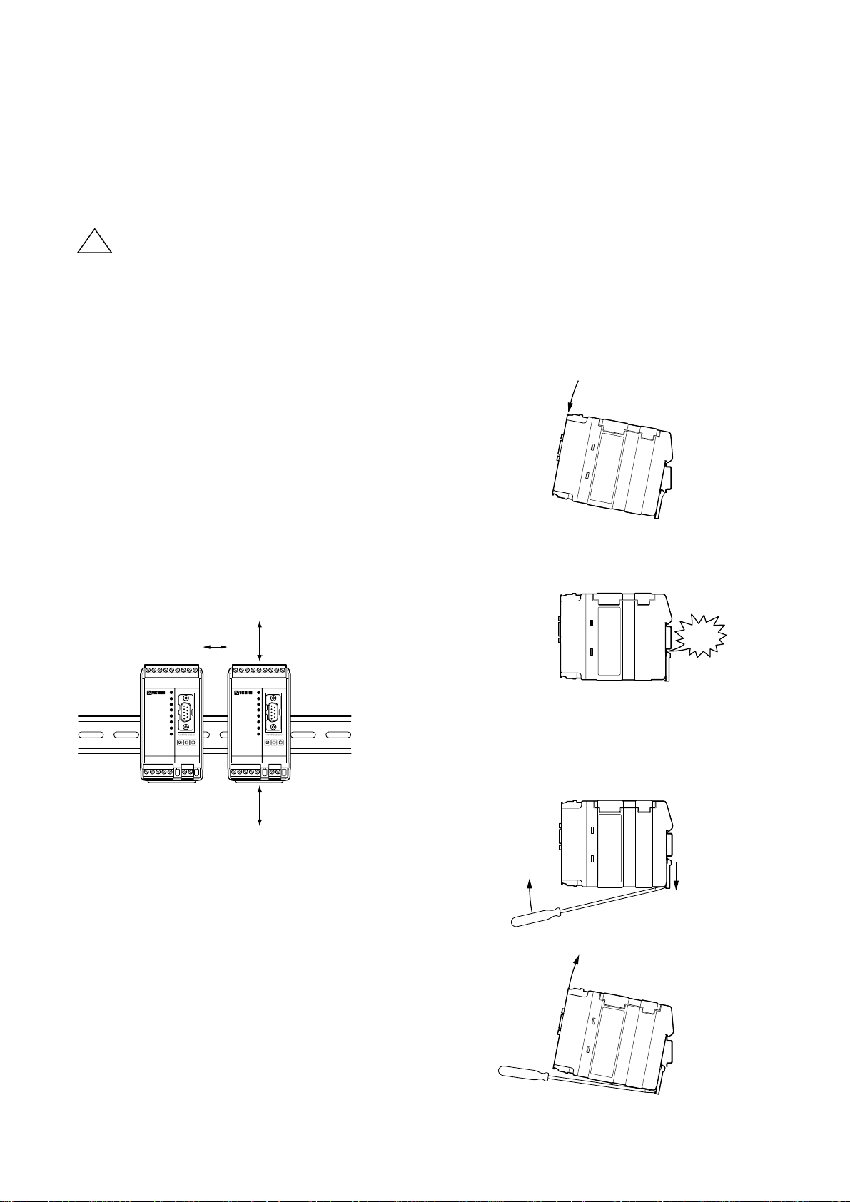
Mounting
This unit should be mounted on 35 mm DIN-rail which is
horizontally mounted on a wall or cabinet backplate.
This unit uses convection cooling. To avoid obstructions to
the airflow around the unit,use the following spacing rules.
Recommended spacing 25 mm (1.0 inch) above/below and
10 mm (0.4 inches) left/right the unit.
Snap on mounting (figure)
Removal
Press down the black support at the back of the unit
using a screwdriver, see figure.
25 mm
Min
10 mm
25 mm
!
CLICK!
Page 9

96609-2211
CH1:RS-422/485
Screw terminal
CH1:RS-232 D-sub
Power screw terminal
CH2: RS-232 D-sub
configuration only
Network
RJ-45 connection
5.2 Connections
CH1 is used for the serial/network conversion.
Type of interface (RS-232 or RS-422/485) connected
must also be set at DIP switch S1. (Ref. section 4.2)
CH2 is used for local configuration.
CH1 and CH2 are not galvanic isolated.
Please use a RS-232 isolator (e.g.Westermo MD-52) if earth voltage differences are
suspected. An isolator,on permanently connected CH2, is required to maintain the
enhanced transient/surge protection.
Page 10

Pin Signal Name*
Number Description V.24 RS-232C
Direction** Description
1 DCD 109 CF Out TCP connection established
2 RD 104 BB Out Received Data
3 TD 103 BA In Transmitted Data
4 DTR 108.2 CD In DTR, close TCP connection
5 SG 102 AB In/out Signal Ground
6 DSR 107 CC Out DSR, ED-10 TCP ready
7 RTS 105 CA In Request to Send
8 CTS*** 106 CB Out Clear to Send
9 RI 125 CE – Ring Indicator, not connected
10 6609-2211
1
2
3
4
5
6
7
8
9
* Functionality might differ from standard, see chapter 6.3
** Direction relative ED-10 TCP.
*** Follows DSR (CTS will be deactivated as required by flow control)
RS-232 cable must not exceed 15 m
CH1: RS-422/485 Connections (Upper left screw terminal)
543
2
1
Terminal
Signal Name*
Number
Marked on According
ED-10 TCP to Standard
Direction** Description
1SG ––Not connected
2T– B Out/In RS-422/485 4-wire Transmitter /
RS-485 2-wire T– and R–
3 T+ A Out/In RS-422/485 4-wire Transmitter /
RS-485 2-wire T+ and R+
4R– B’ In RS-422/485 4-wire Receiver
5R+ A’ In RS-422/485 4-wire Receiver
* Numbered right to left (front view).
** Direction relative ED-10 TCP.
Twisted pair cable is recommended
CH1: RS-232 Connections (D-sub connector), DCE
Page 11

116609-2211
2-wire termination
4-wire termination
5.2.1 RS-422/485 general advice
=Termination
ED-10
Slave unit Slave unit Slave unit
ED-10
Slave unit Slave unit Slave unit
Max 0.3 metre
=Termination
T+
T–
ABABAB
R+
R–
T+
T–
R– R+ R+T– T– B’ A’ B AT+T+ R–
Termination recommendations
The RS-422/485 line must be terminated. The receiver of master and receiver of final bus
slave shall be terminated.
RS-422/485 connection pins can be differently named.For some brands the T+ corresponds to A, but other brands might use some other naming convention.
If a unit does not work it can help to swap A and B.
543
2
1
4-wire
543
2
1
2-wire
Twisted pair cable is recommended
Page 12

12 6609-2211
CH2: RS-232 Connections (D-sub connector), DCE
CH1 and CH2 are not galvanic isolated.
Please use a RS-232 isolator (e.g. MD-52) if earth voltage differences are suspected. An isolator on
permanently connected CH2, is required to maintain the enhanced transient/surge protection of CH1.
5
4
3
2
1
9
8
7
6
Pin Signal Name*
Number Description V.24 RS-232C
Direction** Description
1 DCD 109 CF – Data Carrier Detect, not connected
2 RD 104 BB Out Received Data
3 TD 103 BA In Transmitted Data
4 DTR 108.2 CD – Data Terminal Ready, not connected
5 SG 102 AB In/out Signal Ground
6 DSR 107 CC – Data Set Ready, not connected
7 RTS 105 CA In Request to Send, not used
8 CTS 106 CB Out Clear to Send, not used
9 RI 125 CE – Ring Indicator, not connected
* Functionality might differ from standard, see chapter 7.3
** Direction relative ED-10 TCP.
RS-232 cable must not exceed 15 m
Ethernet 10Base-T Connection (RJ-45 connector),
straight function MDI (no crossover)
Contact Signal Name Direction* Description
1 TD+ Out Transmitted Data
2TD– Out Transmitted Data
3 RD+ In Received Data
4 Not connected
5 Not connected
6RD– In Received Data
7 Not connected
8 Not connected
* Direction relative ED-10 TCP.
CAT 5 cable is recommended.
Unshielded (UTP) or shielded (STP) connector might be used.
8
7
6
5
4
3
2
1
Page 13

136609-2211
5.3 Configuration
5.3.1 DIP switch settings
DIP-switches used to configure the modem are accessable under the lid
on top/front of the unit.
Warning!
Prevent damage to internal electronics from electrostatic discharges (ESD)
by discharging your body to a grounding point (e.g. use of wrist strap),
before the lid on top of the modem is removed.
Warning! Do not open connected equipment.
Prevent access to hazardous voltages by disconnecting the unit from AC/DC
mains supply and all others electrical connections.
NOTE! When configuration via DIP-switches, the
settings of DIP-switches configure the unit
only after a power reset. A setting
configured by any other method
during normal operation,override
the DIP-switch setting. However,
at power up, the DIP-switch settings have precedence over the
setting configured by any other
method.
!
!
Page 14

Termination and fail safe
(4-wire) Channel 1
14 6609-2211
Restore default settings
Channel 2
ON
12345678
S2
Normally in this position
ON
12345678
S2
Restore default settings.
Procedure:
Set and reboot, then
reset and reboot.
Port type
Channel 1
ON
12345678
S1
RS-422/485
ON
12345678
S1
RS-232
2- or 4-wire
Channel 1
ON
12345678
S1
4-wire, RS-422
ON
12345678
S1
2-wire, RS-485
Factory settings
ON
12345678
S2
Channel 2
ON
12345678
S1
Channel 1
ON
12345678
S1
Termination
and fail safe off
ON
12345678
S1
100 Ω termination
between R+ and R–
Terminal open interpreted
as Mark (1)
Termination and fail safe
(2-wire) Channel 1
ON
12345678
S1
Termination
and fail safe off
ON
12345678
S1
100 Ω termination
between T+ and T–
Terminal open interpreted
as Mark (1)
1
2
3
4
5
S1:1-8
Channel 1
S2:1-8
Channel 2
IC 2
Not used with RS-232
Not used with RS-232
Not used with RS-232
Page 15

156609-2211
5.3.2 LED's
CH1: TD Transmitted Data (incoming serial data):
LED off • RS-232 TD = 1, Mark (< –3V) / RS-422/485 = 1, Mark (R+ < R–) /
Not connected.
LED on • RS-232 TD = 0, Space (> 3V) / RS-422/485 = 0, Space (R+ > R).
CH1: RD Received Data (outgoing serial data):
LED off • RS-232 RD = 1, Mark (< –3V) / RS-422/485 = 1, Mark (T+ < T–).
LED on • RS-232 RD = 0, Space (> 3V) / RS-422/485 = 0, Space (T+ > T–).
CH1: RTS Request To Send:
LED off • RS-232 RTS = Off (< –3V)
LED on • RS-232 RTS = On (> 3V)
CH1: CTS Clear To Send:
LED off • RS-232 CTS = Off (< –3V) / RS-422/485 transmitting.
LED on • RS-232 CTS = On (> 3V) / RS-422/485 receiving.
PWR Power:
LED off • No internal power (external power not connected).
LED on • Power OK.
CH2: TD Transmitted Data (incoming serial data):
LED off • RS-232 TD = 1, Mark (< –3V).
LED on • RS-232 TD = 0, Space (> 3V).
CH2: RD Received Data (outgoing serial data):
LED off • RS-232 RD = 1, Mark (< –3V).
LED on • RS-232 RD = 0, Space (> 3V).
CONFIG ED-10 TCP working mode:
LED on • Configuration mode.
LED off • Application mode (or during start up of config. mode).
NET Indication of network status:
LED off • Link Test failed (no network).
LED on • Link Test passed.
LED flashing • Data on Network (traffic).
Page 16

16 6609-2211
5.4 Installation of ED-Tool
This section describes the installation of ED-Tool.
System Requirements:
To install and run the ED-Tool program following requirements are needed.
Minimum:
• 386, 486 or Pentium‚ Processor-based personal computer
• Microsoft‚ Windows‚ 95/98/Me, Windows NT 3.51/4.0‚
or Windows 2000‚ Windows XP, compatible OS.
• 16 MB of RAM for Windows 95/98/Me systems
• 24 MB of RAM for Windows NT systems
• 32 MB of RAM for Windows 2000/XP systems
• CD-ROM drive
• 8 MB of space on hard drive
• Serial and/or Ethernet network connections
• Internet Explorer 5.0 or higher
Recommended:
• Pentium processor-based personal computer
• 32 MB of RAM
Installation:
Remove any previous versions of ED-Tool before installation.
To install ED-Tool
• Insert the ED-Tool CD-ROM into the CD-ROM drive
• Locate the ‘setup.exe’ file on the ED-Tool CD-ROM.
• Run the ‘setup.exe’ and follow the instructions.
Page 17

176609-2211
6. Functional description
The ED-10 TCP can be in either configuration (config) mode or in application (app) mode.
Normally the ED-10 TCP is in app mode, where the serial server is enabled and all configuration settings are readable.
Change of configuration parameters are done in ED-10 TCP config mode.
Configurable parameters are listed in chapter 7.3.
Application mode
In application mode the ED-10 TCP act as a serial server. After reboot it awaits a remote
client to make a TCP connection. When the connection is established all data received at
the network interface will be immediately transmitted at the serial interface CH1. Data
received from the serial interface CH1 is buffered into a data frame according to the
packing algorithm. Each frame is then transmitted at the network interface to the remote
client. Please note that the TCP protocol allows network packets to be split or clumped
together, hence override the packing algorithm. The default packing algorithm shall normally remain unchanged.
When a TCP connection is closed the ED-10 TCP can be set to optionally (mode 2)
transmit a TCP RST message to the client.
The TCP connection is closed by the remote client, any network error or by CH1 DTR
(if DTR control, mode 1, is activated).
In DTR control mode no connections will be established as long as DTR is de-activated.
ED-10 TCP can be configured to accept one specific or all remote client IP addresses.
If all remote clients are accepted an established connection will be closed by a new con-
nection request. This will allow a redundant SCADA controller to "overtake" an already
established connection.
Hardware topology
Page 18

18 6609-2211
The ED-10 TCP network performance can be optimized for minimum delays or minimum
network loading. By default it is optimized for minimum delays, which is the recommended setting under normal conditions. But for transfer of large amount of continuous data at
high serial data rate it is recommended to use mode 4 which is optimized for maximum
throughput and minimum network loading.
Server status information is always available, locally at serial CH2 or remotely by a telnet
connection to port 23.
The packing algorithm can be configured to transmit data immediately or buffer data until
a transmit requirement is fulfilled. The transmit requirement depend on received data at
serial interface CH1 and can be:
1. An end of frame character is received.
2. An end of frame delay has elapsed since last received character.
3. A maximum number of bytes have been received.
The serial server and remote clients are identified by IP address and protocol number.
Configuration mode
Local or remote configuration is managed by either a terminal programme or by ED-Tool.
ED-Tool is a Windows based setup programme, which provides easy configuration.
Configuration is also possible by using terminal programmes (e.g. HyperTerminal for local
configuration or Telnet for remote configuration). A hardware switch ensures restore of
default settings.
Config mode will be entered; automatically by ED-Tool, manually by terminal programme
or when power is switched on with restore default setting switch set.
First time configure: ED-10 TCP is shipped with IP-address 10.0.0.10.
Please make sure that 10.0.0.10 is compliant to your network, before ED-10 TCP
is connected. Otherwise use serial interface to locally set a valid IP address.
A valid IP address must be compliant with the network in use and not chosen arbitrarily,
ask your network administrator when in doubt.
Page 19

196609-2211
7. Configuration
7.1 Configuration by ED-Tool
ED-Tool is intended to be used with a number of products.
This section describes ED-Tool program start and configuration of the ED-10 TCP using
the ED-Tool program.
Before read, write or reboot can be made, Select type of connection.
• Network
• Serial com port must be selected from menu ’Tools – Serial – Port’
• When reading configuration from attached unit the type specific (ED-10 TCP)
property tab will automatically selected and the field ’Type’ in the Staus bar shows the
identity (ED-10 TCP) of the attached unit.
• When writing configuration to attached unit the valid type specific (ED-10 TCP)
property tab shall be selected and none of the parameter fields shall be left empty.
Page 20

20 6609-2211
Program Start:
To star t ED-Tool
• Locate ED-Tool under Program on the Windows Start Menu.
• Click on the ED-Tool icon
• Or locate the ED-Tool icon on the desktop
After the ED-Tool has been successful opened the user is presented with an empty
configuration screen. The user can now get an existing configuration by reading the
configuration from an ED-10 TCP or by opening a configuration file stored on the
system.Or the user can set all configuration parameters by hand.
To configure an ED-10 TCP the user must set all parameters.After the parameters are
set the user can write the configuration to the ED-10 TCP.
Typical configuration procedures:
• Read configuration from an ED-10 TCP
• Change some parameters
• Write configuration to the ED-10 TCP
• Reboot
• Done
or
• Read configuration from a file
• (Change some parameters)
• Write configuration to the ED-10 TCP
• Reboot
• Done
or
• Select the ED-10 TCP property tab
• Set parameters
• Write configuration to the ED-10 TCP
• Reboot
• Done
or
• Select the ED-10 TCP property tab
• Set parameters
• Save configuration to a file
• Done
Page 21

216609-2211
ED-Tool commands
This section describes the ED-Tool commands to be used together with the product
ED-10 TCP.
The commands can be executed by a click on a button or by a menu option.
The commands are described by there use.
Reads configuration parameters from attached ED-10 TCP.
Writes configuration parameters to attached ED-10 TCP.
ED-10 TCP must be re-booted before any new configuration is activated.
Re-boots ED-10 TCP.
ED-10 TCP property tab including type specific (ED-10 TCP) parameters
General parameters.
Exits ED-Tool.
1
2
3
4
5
. . .
. . .
. . .
. . .
1
2
4
3
5
6
6
Page 22

22 6609-2211
7.2 Configuration by terminal
ED-10 TCP internal commands must be used to configure by terminal program.
TYPE command
Configuration parameter values can be read by using the 'type' command. E.g. 'type
chip.set↵', will list the chip.set file.
The 'type' command will list configuration parameters and their values, regardless of the
ED-10 TCP operating mode.
The parameters/values are stored in two pairs of configuration files; chip.set,-ini,
factory.set, -ini. See chapter 6.3.
Values used at reboot are stored in the chip.set, -ini files.
Please note, the configuration files also contain parameters that can not be changed.
COPY and REBOOT commands
The 'copy' and 'reboot' commands are used to change ED-10 TCP working mode. The
contents in ED-10 TCP internal file 'autoexec.bat' decides the mode ED-10 TCP will
enter after a reboot.
The 'copy' command is used to copy the ED-10 TCP internal files 'app.bat' or 'config.bat'
to 'autoexec.bat', e.g. 'copy config.bat autoexec.bat↵'.
Reboot is achieved by either the 'reboot' command or by switching the power off and on.
EXIT command
To change configuration parameter values the ED-10 TCP must be in config mode.
When in config mode a value change is requested by a [parameter] [value] pair input,
e.g. 'datarate 19 200↵'.
When all requested changes have been input the 'exit' command must be used to store
the changes into the configuration files. The 'exit' command also copies app.bat to
autoexec.bat ensuring application mode is entered when ED-10 TCP is rebooted.
Page 23

EXAMPLE 1
Example of how to force the ED-10 TCP into config. mode, change some parameters
and then reboot into application mode with the changed parameters:
Text in terminal window Explanation
'ED-10 TCP APPLICATION MODE'
.
.
.
copy config.bat autoexec.bat↵
reboot↵
ED-10 TCP reboots into config mode.
'ED-10 TCP CONFIGURATION MODE'
>datarate 19200↵
Request a data rate of 19 200 bit/s
ok
>localip 192.168.12.12↵
Request local IP address to be
192.168.12.12
ok
>localport 9000↵
Request 9000 as local protocol port
ok
>exit↵
Establish the requested changes.
Updates configuration files and
ensures application mode after a
reboot.
........
Copied app.bat to autoexec.bat
Parameters successfully altered!
reboot to start ED-10 TCP Application
(Type 'reboot' or power off/on).
ok
>reboot↵
Reboot the ED-10 TCP.
'ED-10 TCP APPLICATION MODE'
.
.
.
236609-2211
Page 24

24 6609-2211
7.2.1 Local configuration
Remove any device connected to serial interface CH1 and connect to ED-10 TCP serial
interface CH2: RS-232 at 19 200 bit/s, no parity, 1 stop bit and no flow control.
7.2.2 Remote configuration
Start Telnet and connect to the ED-10 TCP, using the valid IP-address, (default ‘10.0.0.10’)
username, (default ‘ed10’) and password (default ‘ed10’) as setup at initial configuration.
The Telnet connection will be broken at reboot. A repeated login is required after each
reboot.
EXAMPLE 2
Below follows an example of how to list the current configuration (the type command
can be executed regardless of ED-10 TCP working mode). Parameters that can be
altered, their allowed values and in which file they appear can be found in chapter 6.3
Configurable parameters.
Text in terminal window Explanation
type chip.set↵
.
.
.
REMOTEIP= 168.192.12.12
REMOTEPORT= 9000
.
.
.
type chip.ini↵
.
.
.
[IP]
ADDRESS=168.192.12.10
NETMASK=255.255.255.0
GATEWAY=168.192.12.1
.
.
.
Page 25

256609-2211
7.3 Configurable parameters
Configurable parameters are summarised in the following tables. A more detailed
description follows. Parameter names and valus are case sensitive.
Serial interface
Parameter
Data rate in bits
per second, bit/s
Number of data
bits
None, even or
odd parity
Number of stop
bits
Flow control
ON or OFF.
Parameter
name accepted
DATARATE
dataRate, datarate
baude, BAUDE,
bps
DATABITS
dataBits, databits
PARITY
parity
STOPBITS
stopBits, stopbits
FLOWCONTROL
flowControl
flowcontrol
Allowed values
300–115 200
7 or 8
0, 1 or 2
no, none, odd, even
1 or 2
0 or 1, NO, no,
NONE, none
HW, hw
Apperance
in .ini files
Apperance in .set
files
DATARATE
DATABITS
PARITY
STOPBITS
FLOWCONTROL
Remarks
0=none, 1=odd
2=even
Two stop bits only
when no parity is
selected.
0=NO, 1=HW
Parameter
End of Frame
Character ASCII
value
End of Frame
Delay in ms
Maximum number of bytes in
Frame
Send End of
Frame Character
Parameter
name accepted
EOFCHARACTER
eofChar, eofchar
eofcharacter
EOFDELAY
eofDelay, eofdelay
MAXBYTEFRAME
maxByteFrame
maxbyteframe
EOFCHARSEND
eofCharSend
eofcharsend
Allowed values
0–256
0–2 550
1–1 500
0 or 1
Apperance
in .ini files
Apperance in .set
files
EOFCHARACTER
EOFDELAY
MAXBYTEFRAME
EOFCHARSEND
Remarks
256 = No EoF
Character. (EoF character not used).
0 = No EoF Delay
(EoF Delay not used).
This parameter might
be override by TCP
0 will remove the EoF
Character before data
is sent over network.
Packing algorithm
Page 26

26 6609-2211
Parameter
Local IP Address
Gateway
IP Address
Subnet Mask
Local Protocol
Port
Remote
IP Address
Remote
Protcol Port
Telnet User
Name
Telnet Password
Mode
Parameter
name accepted
ADDRESS
localIPStr,
LOCALIP
localip, localIP
GATEWAY
gatewayIPStr
gateway
NETMASK
subnetMaskStr
netmask
LOCALPORT
localPort,
localport
REMOTEIP
remoteIPStr
remoteIP,
remoteip
REMOTEPORT
remotePort
remoteport
USER, user
telnetUser
PASSWORD
password
telnetPassword
MODE, mode
Allowed values
1.0.0.0 - 126.0.0.0
128.1.0.0 -
191.255.0.0
192.0.1.0 -
223.255.255.0
224.0.0.0 -
255.255.255.254
Dotted decimal
notation
1 - 20, 22, 24 - 79
81 - 65535
Above IP addresses
and broadcast addr.
1 - 65535
Any name up to 19
characters long
(no spaces)
Any word up to 19
characters long
(no spaces)
0, 1, 2, 3, 4
Apperance
in .ini files
[IP]
ADDRESS
[IP]
GATEWAY
[IP]
NETMASK
[TELNET]
USER0
USER1
[TELNET]
PASSWORD0
PASSWORD1
Apperance in .set
files
LOCALPORT
REMOTEIP
REMOTEPORT
MODE
Remarks
IP addr. in dotted
decimal notation
The protocol port used
in application mode.
User name for remote
configuration.
Password for remote
configuration
0=> Default.
1=> DTR Control
2=> RST at TCP-close
4=> Min. network
loading.
Network interface
Port Type (only by switches)
The port type is manually selected, between RS-232 or RS-422/485, by DIP-switches.
The RS-232 port is physically a 9 pin D-sub connector and RS-422/485 is a screw
terminal block.
Port type RS-422/485 uses a transceiver supporting both RS-422 and RS-485.
2- or 4-wire (half or full duplex) is manually selected by DIP-switches.
The transceiver is automatically switched between transmit and receive mode by
incoming network data packets.
Default port type is RS-232.
255.255.255.255
= All IP accepted.
Ignored, not used
The protocol port used
in application mode.
21, 23, 80
Dotted decimal
notation
Page 27

276609-2211
7.3.1. Serial interface
Data Rate
The data rate can be set from 300 bit/s to 115.2 kbit/s.
Default is 19 200 bit/s.
Data Bits
Seven (7) or eight (8) data bits can be selected.
Default is eight data bits.
Parity
No, odd or even parity can be selected.
Default is no parity.
Stop Bits
Two (2) stop bits can be set if no parity is selected.
Default is one (1) stop bit.
Flow Control
Flow control can be chosen between none or hardware. Hardware flow control is managed by the CTS and RTS signal. CTS is switched off (<-3 V) when the ED-10 TCP serial
receive buffer is near full. The buffer size is 10 kB. Serial data from ED-10 TCP will be
transmitted if the RTS is on (>3 V).
Flow control is ignored for port type RS-422/485.
Default, flow control is switched off (none) and the CTS will follow DSR.
Termination and Failsafe (Only by switches)
Termination and fail-safe is used for port type RS-422/485 and can be manually switched
on or off. Switch pair S1:7,8 is used in 2-wire mode. In 4-wire mode switch pairs S1:5,6
are used.
Default is termination and failsafe switched off, i.e. all switch pairs off.
Page 28

28 6609-2211
7.3.2. Packing algorithm
End of frame character, EoF Char
ASCII code of character indicating end of frame (0-255). The serial data buffered will be
sent over network when this character 0 - 255 is detected (e.g. 13 for Carriage return).
256 will deactivate this function.
Allowed values are 0 – 256.
Default is 256, i.e. deactivated.
End of Frame Delay
The time, after last received character, ED-10 TCP delays until the buffered data frame
is sent over network. Allowed values are 0-2550 ms, 1–9 in 1 ms step and 10–2550 in
10 ms step. The value will be rounded to the nearest lower step (e.g. 128 => 120 ms,
132 =>130 ms).
The value zero (0) deactivates this function, i.e. wait until other criteria is true.
Default value is 20 ms.
If EoF delay is used with low data rates, it should be set to at least one character time.
Note.
Latency has to be added to calculate total delay of data.
Maximum number of bytes/characters in frame
The maximum number of bytes that will be buffered in the data frame. When the data
frame is full the data will be transmitted over network.
Allowed values are 1–1500 bytes. Values above 255 are approximate.
Default is 1000 bytes.
TCP might override this setting.
Transmit end of frame character
Include end of frame character in Network data packet. Allowed alternatives are yes
or no. Default is yes.
Page 29

296609-2211
7.3.3. Network interface
Local IP address*
Local IP address is used as the first part of local end point identity, in both application
and configuration mode. Do not use Network ID or Broadcast address.
Default is 10.0.0.10.
Local Protocol Port*
The protocol port is the second part of a end point identity. This local TCP port is used
only in application mode. The remote client (computer) must address this local port to
establish a TCP connection.
Allowed values are 1–20, 22, 24–79, 81 - 65535 (>1024 recommended). Port 23 shall
be used for configuration and status information. Port 21 and 80 can not be used.
Please observe that ports 1–1024 are “well-known ports”, hence commonly used by
other programs (e.g. FTP, Telnet, NETBIOS, mail etc). “well-known ports” should
normally not be used by ED-10 TCP. All ”well-known” ports can be found at
http://www.iana.org/assignments/port-numbers
Default is 9000.
Remote IP address*
Required IP address of remote client (computer). The ED-10 TCP will only accept connections (clients) with the Remote IP address. Remote IP address 255.255.255.255 will
force the ED-10 TCP to accept any (all) connections.
An established connection will be closed by a new connection request, if the Remote IP
address is set to 255.255.255.255.
If the Remote IP not are equal to 255.255.255.255 an established connection will remain
established and any new connection requests will be refused.
Default is 255.255.255.255.
Remote Protocol Port
The remote protocol port is not used, hence ignored.
Netmask*
The Netmask is used for Subnet addressing.
Default is 255.255.255.0.
* The IP address must be compliant to the attached network. Ask the network administrator when
in doubt.
Page 30

30 6609-2211
Gateway IP address*
The Gateway IP address is used for indirect delivery of network packets when the
Remote IP address is not a part of the Network of Local IP address. When the remote
client address is at a different network the packet is sent to the gateway IP address,
which must belong to a router (gateway).
The router will then forward the network packet to its destination (remote client
address). The Local IP address and the Netmask define the network extent.
The Gateway IP address must be on the same net as the local IP, otherwise 0.0.0.0 is
used.
Default is 10.0.0.10.
Telnet user name
User name for remote configuration and status information over network (telnet login).
Default is ed10.
Telnet password
Password for remote configuration and status information over network (telnet login).
Default is ed10.
7.3.4. Mode
The ED-10 TCP can be set into four different modes; Default (0), DTR Control (1), RST
at TCP close (2) and Min. network loading (4).
By default the serial DTR control signal is ignored. But in mode 1 (DTR control) the
ED-10 TCP will await activation of DTR (control signal at CH1: RS-232) before it accept
remote clients and establish a connection. An established connection will further be
closed by de-activation of DTR.
In mode 2 a RST (reset) message is transmitted at the network interface when a connection is closed. By default there is no RST added to the normal close handshaking.
Mode 4 is only recommended for transfer of large amount of continuous data at high
serial data rate. This mode 4 is optimized for maximum throughput and minimum network loading.
By default the ED-10 TCP network performance is optimized for minimum delays.
7.3.5. MAC address
The MAC address of the unit can be found on the product label “00 30 56 F” + last 5
digits on IC2 see figure in section 4.2 Switch settings on page 11. Example: Label on IC2
“SC12 RTOS 0092C2” this will give the unit MAC address “00 30 56 F0 92 C2”
The MAC address can also be find out with the DOS command “ARP –a”.
(Perform the “PING” command with the ED-10 local IP address before the ARP
command.)
* The IP address must be compliant to the attached network. Ask the network administrator when
in doubt.
Page 31

316609-2211
8. Application examples
This application can be achieved using one of the methods described in section 1.
For solution 1 Telnet can be found in Microsoft Windows. Connect to the ED-10
TCP Local IP and Local Port.
For solution 2 You will find an example of a COM port redirector software on the
enclosed CD – “\Software\Tactical software\Software”.
This is a 30 days free evaluation copy.
To purchase a full licence please contact Westermo.
For setup of the redirector software “Serial/IP” read the QuickStart
and the UserGuide that can be found in the directory
“\Software\Tactical software\Manual” on the enclosed CD.
For solution 3 The software must be written to directly access the network inter-
face (socket compliant) of the ED-10 TCP.
A sample written in C++ can be found on the CD
“\Software\Sample\sample.zip”
PC with solution 1, 2 or 3
Switch
Switch
Switch
LAN
ED-10
TCP
RS-232/422/485
Serial Device
Serial Device
ED-10
TCP
RS-232/422/485 RS-232/422/485
ED-10
TCP
Serial Device
LAN
Page 32

T03-0390 • 6609-2211 03.07 Mälartryck AB, Eskilstuna, Sweden
Westermo Teleindustri AB • SE-640 40 Stora Sundby, Sweden
Phone +46 16 42 80 00 Fax +46 16 42 80 01
E-mail:info@westermo.se
W estermo W eb site: www.w estermo.com
Westermo Teleindustri AB have distributors in several
countries, contact us for further information.
Westermo Data Communications Ltd
Unit 14 Talisman Business Centre • Duncan Road
Park Gate, Southampton • SO31 7GA
Phone:+44(0)1489 580 585 • Fax.:+44(0)1489 580586
E-Mail:sales@westermo.co .uk
Westermo Data Communications GmbH
Goethestraße 67,68753 Waghäusel
Tel.: +49(0)7254-95400-0 • Fax.:+49(0)7254-95400-9
E-Mail:info@westermo.de
Westermo Data Communications S.A.R.L.
9 Chemin de Chilly 91160 CHAMPLAN
Tél :+33 1 69 10 21 00 • Fax : +33 1 69 10 21 01
E-mail :infos@westermo.fr
Subsidiaries
 Loading...