

Page 1

Industrial Ethernet adapter
INSTALLATION MANUAL
6609-2202
www.westermo.se
ED-10
©
Westermo Teleindustri AB • 2001 • REV. A
Galvanic
Isolation
Transient
Protection
Balanced
Transmission
CE
Approved
Page 2

Page 3

36609-2202
Contents
1. Introduction
.......................................................................................................................................................................... 4–5
2. Safety ............................................................................................................................................................................................................ 5
3. Specification ......................................................................................................................................................................... 6–7
4. Installation ....................................................................................................................................................................................... 8
4.1 Connections
............................................................................................................................................ 8–10
4.2 DIP switch settings
.............................................................................................................................. 11
4.3 LED indicators
............................................................................................................................................ 12
4.4 Installation of ED-Tool
.................................................................................................................. 13
5. Functional description ......................................................................................................................... 14–15
6. Configuration ........................................................................................................................................................................ 16
6.1 Configuration by ED-Tool
............................................................................................. 16–22
6.2 Configuration by terminal
............................................................................................ 22–24
6.3 Delayed configuration
......................................................................................................... 25–26
6.4 Configurable parameters
............................................................................................... 27–31
7. Application examples ............................................................................................................................ 32–34
Page 4

4 6609-2202
1. Introduction
The ED-10 is an Industrial Ethernet Adapter with a serial interface. The type of serial
interface is selectable between RS-232 and RS-422/485. The Ethernet interface is
10BaseT and TCP/IP Internet Protocols are used for network communication.
Two ED-10 units can be used to provide a serial point to point link over a TCP/IP network. Each ED-10 passes data from its serial interface to the other unit's serial interface.
This enables long distance serial connections over pre-existing networks.
It is also possible to communicate one to many (e.g. master/slaves), by using a broad-
cast address.
If the customer writes it’s own PC application software, the network interface of ED-10
can be directly accesed.
A software example can be downloaded from the Westermo web site
(www.westermo.se). This example demonstrates how a PC sends network data directly
to the ED-10. Source code, in C, is included.
ED-10 point to point connection
ED-10 one to many connection
ED-10 directly accessed by a PC-application
543
2
1
543
2
1
Serial
Device
Serial
Device
ED-10
Network
ED-10
543
2
1
543
2
1
Serial
Master
Collision Domain
Serial
Slave
Serial
Slave
ED-10
ED-10
Network
Network
543
2
1
ED-10
543
2
1
ED-10
Serial
Slave
543
2
1
ED-10
Serial device
Page 5

56609-2202
The ED-10 is ideal for use in the industrial environment. It is housed in the Westermo
DIN rail box and has a wide range power input, isolated interfaces and transient protection.
The ED-10 is approved for Industrial EMC Immunity (EN50082-2) and EMC Emission
(EN50081-1). All relevant requirements of the Low Voltage Directive are fulfilled.
The ED-10 uses the TCP/IP Internet Protocol Suit (TCP/IP) to transfer data over the
network.
TCP/IP is a set of protocols that enables communication across local and wide area
networks and includes protocols such as TCP, UDP, IP , ARP, RARP, ICMP. Although
not all these protocols are needed for a network data transfer.
The ED-10 uses TCP for remote configuration (configuration mode) and UDP for
transmitting the serial data over network, i.e. UDP is used in application mode.
UDP uses packet delivery of data, meanwhile TCP uses stream transport.
The ED-10 can be configured both remotely over the TCP/IP network and locally via the
RS-232 interface, making the unit very flexible.
Local or remote configuration is achieved either by using the ED-Tool Windows‚ software or by using a terminal programme (e.g. HyperTerminal for local configuration or
Telnet for remote configuration).
A DIP switch setting also allows the unit to be reset to factory default, if required.
2. Safety
Serial interface CH1 is not isolated from CH2. They must only be connected to SELV
circuits.
The Network interface must only be connected to TNV or SELV circuits.
See EN 60950:1996 for definitions.
Sound installation practice, as defined by applicable local codes or regulations, shall be
followed in every instance in which such practice is applicable.
Page 6

6 6609-2202
3. Specification
Network Interface 10BASE-T. IEEE std 802.3, 2000 Edition.
Data rate 10 Mbit/sec, half duplex.
Mechanical RJ-45 Modular Jack (ISO/IEC 8877:1992),
Unshielded or shielded (UTP/STP).
Serial Interface 1 (CH 1) RS-232 or RS-422/485
Data rate 300–115 200 bit/s Full, half duplex or simplex.
Data format 7–8 Data Bits, Odd, Even or None Parity Bit,
1–2 Stop Bits (2 stop bits when no parity only)
Control signals* RTS, CTS, DSR
Termination** Termination and fail safe, on or off
Mechanical RS-232: 9-pin female D-sub.
RS-422/485: Screw Terminal.
Serial Interface 2 (CH 2) RS-232 (used for local configuration only)
Data rate 19 200 Bit/sec
Data format 8 Data Bits, No Parity Bit, 1 Stop Bit
Mechanical 9-pin female D-sub.
Power Interface
Rated voltage 12–49 V AC / 10–74 V DC polarity independent.
Rated current 350 mA
Rated frequency 50–60 Hz
Mechanical Screw Terminal.
Isolation Functional and safety
Power Interface to 4.2 kV DC, 3 kV RMS @ 50–60 Hz. EN 60950:1996
all other Interfaces***
Network Interface 2.1 kV DC, 1.5 kV RMS @ 50–60 Hz. Applied for 60 sec
to serial interface as specified in 5.3.2 of EN 60950:1996.
Transient Protection
Power Interface ±4 kV, EN 61 000-4-5:1995 Class 4
Network Interface ±2 kV, EN 61 000-4-5:1995 Class 3
Serial Interface** ±2 kV, EN 61 000-4-5:1995 Class 3
Serial Interface* ±0.5 kV, EN 61 000-4-5:1995 Class 1
Application Serial/Network conversion
Latency (minimum) Serial to Network: 2 ms
Network to Serial: 8 ms
Throughput (maximum) 57.6 kbit/s (1.44 Mbyte data)
Network protocols UDP, IP, ARP
* RS-232 only.
** RS-422/485 only.
*** Power to network interface, 1.5 kV RMS @ 50–60 Hz functional isolation.
Page 7

76609-2202
Configuration Remotely over Network or locally at serial interface.
Windows based PC-programme or simple terminal
programme. Delayed configure possible.
Indicators (LED) TD, RD, CTS, RTS, PWR, TD, RD, CONFIG, NET
Environment 5–50°C
5–95% REL non condensing
Dimension 55x100x128 mm (WxHxD)
Weight 0.35 kg
Mounting On 35 mm DIN-rail
Approvals CE
Page 8

8 6609-2202
4. Installation
Power connection is made at
lower right screw terminal.
Connect PLC, computer etc
to serial interface CH1. Use
RS-232 or RS-422/485.
Serial interface CH2: RS-232
shall be used for configuration
only.
4.1. Connections
CH1 is used for the serial/network conversion.
Type of interface (RS-232 or RS422/485) connected
must also be set at DIP switch S1.
CH1: RS-232 Connections (D-sub connector), DCE
543
2
1
1
2
3
4
5
6
7
8
9
Pin Signal Name*
Number Description V.24 RS-232C
Direction** Description
1 DCD*** 109 CF Out Data Carrier Detect
2 RD 104 BB Out Received Data
3 TD 103 BA In Transmitted Data
4 DTR 108.2 CD In Data Terminal Ready
5 SG 102 AB In/out Signal Ground
6 DSR 107 CC Out Data Set Ready, ED-10 ready
7 RTS 105 CA In Request to Send
8 CTS*** 106 CB Out Clear to Send
9 RI 125 CE – Ring Indicator, not connected
* Functionality might differ from standard, see chapter 6.4
** Direction relative ED3-10.
*** Follows DSR (CTS will be deactivated as required by flow control)
RS-232 cable must not exceed 15 m
CH1: RS-422/485
Screw terminal
CH1: RS-232
9-pin D-sub
CH2: RS-232
9-pin D-sub
configuration only
Network
RJ-45 connection
Power
screw terminal
Page 9
96609-2202
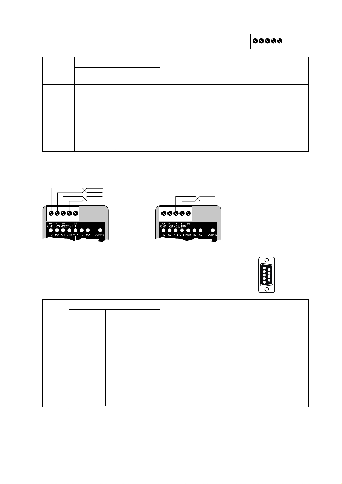
CH1: RS-422/485 Connections (Upper left screw terminal)
543
2
1
Terminal
Signal Name*
Number
Marked According
on ED-10 to Standard
Direction** Description
1 SG – – Not connected
2 T– B Out/In RS422/485 4-wire Transmitter /
RS485 2-wire T– and R–
3 T+ A Out/In RS422/485 4-wire Transmitter /
RS485 2-wire T+ and R+
4 R– B’ In RS422/485 4-wire Receiver
5 R+ A’ In RS422/485 4-wire Receiver
* Numbered right to left (front view).
** Direction relative ED-10.
Twisted pair cable is recommended
CH2: RS-232 Connections (D-sub connector), DCE
5
4
3
2
1
9
8
7
6
Pin Signal Name*
Number Description V.24 RS-232C
Direction** Description
1 DCD 109 CF – Data Carrier Detect, not connected
2 RD 104 BB Out Received Data
3 TD 103 BA In Transmitted Data
4 DTR 108.2 CD – Data Terminal Ready, not connected
5 SG 102 AB In/out Signal Ground
6 DSR 107 CC – Data Set Ready, not connected
7 RTS 105 CA In Request to Send, not used
8 CTS 106 CB Out Clear to Send, not used
9 RI 125 CE – Ring Indicator, not connected
* Functionality might differ from standard, see chapter 6.4
** Direction relative ED-10.
RS-232 cable must not exceed 15 m
543
2
1
4-wire
543
2
1
2-wire
Page 10

10 6609-2202
Ethernet 10Base-T Connection (RJ-45 connector),
straight function (no crossover)
Contact Signal Name Direction1 Description
1 TD+ Out Transmitted Data
2 TD- Out Transmitted Data
3 RD+ In Received Data
4 Not connected
5 Not connected
6 RD- In Received Data
7 Not connected
8 Not connected
* Direction relative ED-10.
CAT 5 cable is recommended.
Unshielded (UTP) or shielded (STP) connector might be used.
1
2
34
5678
Page 11
116609-2202
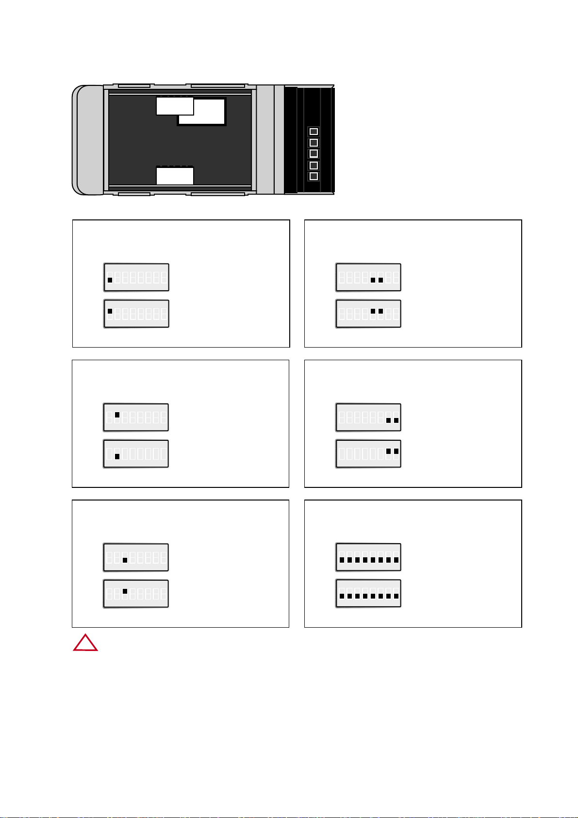
Restore default settings
Channel 2
4.2 Switch Settings
ON
12345678
S2
Normally in this position
ON
12345678
S2
Forced into configuration
mode at power ON or
reboot. Restore default
settings.
Port type
Channel 1
ON
12345678
S1
RS-422/485
ON
12345678
S1
RS-232
2- or 4-wire
Channel 1
ON
12345678
S1
4-wire
ON
12345678
S1
2-wire
Factory settings
ON
12345678
S2
Channel 2
ON
12345678
S1
Channel 1
Termination and fail safe
(4-wire) Channel 1
ON
12345678
S1
Termination
and fail safe off
ON
12345678
S1
120 Ω termination
between R+ and R–
Terminal open interpreted
as Mark (1)
Termination and fail safe
(2-wire) Channel 1
ON
12345678
S1
No termination
and fail safe
ON
12345678
S1
120 Ω termination
between T+ and T–
Terminal open interpreted
as Mark (1)
1
2
3
4
5
S1:1-8
Channel 1
S2:1-8
Channel 2
IC 2
ESD
Only touch switching element of DIP switch.
!
Page 12

12 6609-2202
4.3 LED's
CH1: TD Transmitted Data (incoming serial data):
LED off • RS-232 TD = 1, Mark (< -3V) / RS-422/485 = 1, Mark (R+ < R–) /
Not connected.
LED on • RS-232 TD = 0, Space (> 3V) / RS-422/485 = 0, Space (R+ > R).
CH1: RD Received Data (outgoing serial data):
LED off - RS-232 RD = 1, Mark (< -3V) / RS-422/485 = 1, Mark (T+ < T–).
LED on - RS-232 RD = 0, Space (> 3V) / RS-422/485 = 0, Space (T+ > T–).
CH1: RTS Request To Send.
LED off • RS-232 RTS = Off (< -3V)
LED on • RS-232 RTS = On (> 3V)
CH1: CTS Clear To Send.
LED off • RS-232 CTS = Off (< -3V) / RS-422/485 transmitting.
LED on • RS-232 CTS = On (> 3V) / RS-422/485 receiving.
PWR Power:
LED off • No internal power (external power not connected).
LED on • Power OK.
CH2: TD Transmitted Data (incoming serial data):
LED off • RS-232 TD = 1, Mark (< -3V).
LED on • RS-232 TD = 0, Space (> 3V).
CH2: RD Received Data (outgoing serial data):
LED off - RS232 RD = 1,Mark (< -3V).
LED on - RS232 RD = 0,Space (> 3V).
CONFIG ED-10 working mode:
LED on • Configuration mode.
LED off • Application mode (or during start up of config. mode).
NET Indication of network status:
LED off • Link Test failed (no network).
LED on • Link Test passed.
LED flashing • Data on Network (traffic).
Page 13

136609-2202
4.4 Installation of ED-Tool
This section describes the installation and program start of the ED-Tool.
System Requirements:
To install and run the ED-Tool program following requirements are needed.
Minimum:
• 386, 486 or Pentium‚ Processor-based personal computer
• Microsoft‚ Windows‚ 95/98/Me, Windows NT 3.51/4.0‚ or
Windows 2000‚ compatible OS.
• 16 MB of RAM for Windows 95/98/Me systems
• 24 MB of RAM for Windows NT systems
• 32 MB of RAM for Windows 2000 systems
• CD-ROM drive
• 8 MB of space on hard drive
• Serial and/or ethernet network connections
• Internet Explorer 5.0 or higher
Recommended:
• Pentium processor-based personal computer
• 32 MB of RAM
Installation:
To install ED-Tool
• Insert the ED-Tool CD-ROM into the CD-ROM drive.
• Locate the edtool30.exe file on the ED-Tool CD-ROM.
• Start the edtool30.exe and follow the instructions.
Program Start:
To start ED-Tool
• Locate ED-Tool under Program on the Start-Menu.
• Click on the ED-Tool icon
• Or locate the ED-Tool icon on the desktop
Page 14

14 6609-2202
5. Functional description
The ED-10 can be in either configuration (config) mode or in application (app) mode.
Normally the ED-10 is in app mode, where the serial-to-network conversion is enabled
and all configuration settings are readable.
Change of configuration parameters are done in ED-10 config mode. Configurable
parameters are listed in chapter 6.4.
Application mode
In application mode the ED-10 transfers data between the serial interface (CH1) and the
network interface (10BaseT).
At the network interface data are received as datagrams (network packets). Each received
network packet is immediately transmitted at the serial interface CH1.
Data received from the serial interface CH1 is buffered into a data frame according to the
packing algorithm. Each frame is then transmitted as a datagram at the network interface.
Hardware topology
Page 15

156609-2202
The packing algorithm can be configurated to transmit data immediately or buffer data
until a transmit requirement is fulfilled. The transmit requirement depend on received
data at serial interface CH1 and can be:
1. An end of frame character is received.
2. An end of frame delay has elapsed since last received character.
3. A maximum number of bytes have been received.
Recommended configuration of the packing algorithm can be found in the sample applications chapter.
When the ED-10 is used in pairs, to establish a serial point to point connection over
network, each point is identified by its IP address and protocol port number.
One points local identity must match with the other points Remote identity, i.e there
is a "cross-relation" between the two points identities.
It is also possible to communicate one to many (e.g master/slave), by using a broadcast
IP address (e.g. 255.255.255.255). Both directed and limited broadcast is supported.
Configuration mode
Local or remote configuration is managed by either a terminal programme or by
ED-Tool.
ED-Tool is a Windows based set-up programme which provides easy configuration.
Configuration is also possible by using terminal programmes (e.g HyperTerminal for
local configuration or Telnet for remote configuration). A hardware switch ensures
restore of default settings.
Config mode will be entered; automatically by ED-Tool, manually by terminal programme
or when power is switched on with restore default setting switch set.
First time configure: ED-10 is shipped with IP-address 10.0.0.10.
Please make sure that 10.0.0.10 is compliant to your network,
before ED-10 is connected. Otherwise use serial interface to locally
set a valid IP address.
A valid IP-address must be compliant with the network in use and not chosen arbitrarily,
ask your network administrator when in doubt.
Page 16

16 6609-2202
6. Configuration
6.1 Configuration by ED-Tool
This section describes configuration of the ED-10 using the ED-Tool program.
After the ED-Tool has been successful opened the user is presented with an empty configuration screen. The user can now get an existing configuration by reading the configuration from an ED-10 or by opening a configuration file stored on the system. Or the
user can set all configuration parameters by hand.
To configure an ED-10 the user must set all parameters. After the parameters are set
the user can write the configuration to the ED-10.
Typical configuration procedures:
• Read configuration from an ED-10
• Change some parameters
• Write configuration to the ED-10
• Done
or
• Read configuration from a file
• Change some parameters
• Write configuration to the ED-10
• Done
or
• Set parameters
• Write configuration to the ED-10
• Done
Page 17

176609-2202
ED-Tool commands
This section describes the ED-Tool commands.
The commands can be executed by a click on a button or by a menu option.
The commands are described by there use.
1
2
3
4 5
1
2
3
4
5
Reads configuration parameters from attached ED-10.
Writes configuration parameters to ED-10.
ED-10 must be re-booted before any new configuration is activated.
Re-boots ED-10.
Help information.
Exits ED-Tool.
Page 18

18 6609-2202
New configuration file
File – New Default parameters are set
Load configuration file
File – Load Load a pre-stored configuration file
from the system.
Save configuration file
File – Save Save a configuration file or system files
on the local system.
Page 19

196609-2202
Exit ED-Tool (Button Exit)
File – Exit ED-Tool close and exit.
Read configuration file
Tools – Read Configuration parameters
are read from an ED-10.
Write configuration file (Button Write)
Tools – Write Configuration parameters
are written to an ED-10.
Page 20

20 6609-2202
Reboot (Button Reboot)
Tools – Reboot ED-10 reboots.
View configuration file
Tools – View – File Files are viewed correctly
in a View window.
Page 21

216609-2202
Set connection
Tools – Serial Serial and network connection
parameters are displayed and
can be altered.
Help
Help - ? ED-Tool help system (not currently used).
Page 22

22 6609-2202
The configuration parameters can be read from an ED-10 or a file and altered or be
written to an ED-10 or a file. All parameters must be set before any other action like
write, view or generate configuration can take place. For more information about the
parameters see the following section.
The configuration parameters can be altered by choosing or editing a value in the parameter field. The fields can be set with values in the min-max range or with a default value
specified for each parameter.
6.2 Configuration by terminal
ED-10 internal commands must be used to configure by terminal program.
TYPE command
Configuration parameter values can be read by using the 'type' command. E.g. 'type
chip.set↵', will list the chip.set file.
The 'type' command will list configuration parameters and their values, regardless of the
ED-10 operating mode.
The parameters/values are stored in three pairs of configuration files; chip.set,-ini,
factory.set,-ini, delayed.set,-ini. See chapter 6.4.
Values used at re-boot are stored in the chip.set, -ini files. The files delayed.set, -ini holds
values used if delayed configuration is activated.
Please note, the configuration files also contain parameters that can not be changed.
COPY and REBOOT commands
The 'copy' and 'reboot' commands are used to change ED-10 working mode. The contents in ED-10 internal file 'autoexec.bat' decides the mode ED-10 will enter after a reboot.
The 'copy' command is used to copy the ED-10 internal files 'app.bat' or 'config.bat' to
'autoexec.bat', e.g. 'copy config.bat autoexec.bat↵'.
Re-boot is achieved by either the 'reboot' command or by switching the power off-on.
EXIT command
To change configuration parameter values the ED-10 must be in config mode. When in
config mode a value change is requested by a [parameter] [value] pair input, e.g 'datarate
19 200↵'.
When all requested changes have been input the 'exit' command must be used to store
the changes into the configuration files. The 'exit' command also copies app.bat to
autoexec.bat ensuring application mode is entered when ED-10 is re-booted.
Page 23

EXAMPLE 1
Example of how to force the ED-10 into config. mode, change some parameters and
then re-boot into application mode with the changed parameters:
Text in terminal window Explanation
'ED-10 APPLICATION MODE'
.
.
.
copy config.bat autoexec.bat↵
reboot↵
ED-10 re-boots into config mode.
'ED-10 CONFIGURATION MODE'
>datarate 19200↵
Request a data rate of 19 200 bit/s
ok
>localip 192.168.12.12↵
Request local IP address to be
192.168.12.12
ok
>localport 9000↵
Request 9000 as local protocol port
ok
>exit↵
Establish the requested changes.
Updates configuration files and
ensures application mode after a
re-boot.
........
Copied app.bat to autoexec.bat
Parameters successfully altered!
Re-boot to start ED-10 Application
(Type 'reboot' or power off/on).
ok
>reboot↵
Re-boot the ED-10.
'ED-10 APPLICATION MODE'
.
.
.
236609-2202
Page 24

24 6609-2202
EXAMPLE 2
Below follows an example of how to list the current configuration (the type command
can be executed regardless of ED-10 working mode). Parameters that can be altered,
their allowed values and in which file they appear can be found in chapter 6.4-configurable parameters.
Text in terminal window Explanation
type chip.set↵
.
.
.
REMOTEIP= 168.192.12.12
REMOTEPORT= 9000
.
.
.
type chip.ini↵
.
.
.
[IP]
ADDRESS=168.192.12.10
NETMASK=255.255.255.0
GATEWAY=168.192.12.1
.
.
.
Page 25

256609-2202
6.2.1 Local configuration
Remove any device connected to serial interface CH1 and connect to ED-10 serial interface CH2: RS-232 at 19 200 bit/s, no parity, 1 stop bit and no flow control.
6.2.2 Remote configuration
Start Telnet and connect to the ED-10, using the valid IP-address, (default 10.0.0.10)
user name and password as set-up at initial configuration.
The Telnet connection will be broken at re-boot. A repeated login is required after each
re-boot.
6.3 Delayed configuration
The delayed configuration facility allows the ED-10 to be automatically re-configured, up
to a week after the previous re-boot.
This enables automatic ED-10 management at, for instance, weekends or nights.
Automatic re-configure is easy activated using ED-Tool:
1. Press 'Read config' button. The active (old) configuration will be shown.
2. Check the 'Delayed Config' and insert the requested delay.
3. Change the parameters to be delayed re-configured.
4. Press 'Write config' button.
5. Press 'Reboot'. The ED-10 will start app mode with the old (active)
configuration and then automatically re-configure after <delayedconfigure>
minutes.
The ED-10 application mode will always run configured as given by the chip.ini, -set files.
If the configureDelay parameter is not zero (0) minutes the ED-10 will automatically
copy the delayed.ini, -set files to the chip.ini, -set files and re-boot.
Hence the ED-10 will re-boot and start the application mode with changed
configurations.
This automatic re-configuration will take place <configureDelay> minutes after the
preceeding re-boot.
Page 26

All requested value changes written (by a 'exit' command or the 'write config' button)
together with configure delay not equal zero will be activated when the ED-10 is re-configured. Requesting delayed configure to be zero, followed by a 'write config', will deactivate automatic re-configure.
An example of how to use a terminal to activate automatic re-configure, when ED-10 is
in config mode:
Text in terminal window Explanation Explanation
>type chip.set↵ List current settings.
REMOTEIP= 168.192.12.12 This is the active IP-address.
REMOTEPORT= 12000 This is the active Protocol port.
.
.
>remoteip 168.190.10.10↵
Request new IP-address.
ok
>remoteport 20001↵
Request new Protocol port.
ok
>configuredelay 360↵
Request re-configure after 6 hours.
ok
>exit↵
Updates configuration files and
ensures application mode
after a re-boot.
........
Copied app.bat to autoexec.bat
Parameters successfully altered!
Re-boot to start ED-10 Application
(Type 'reboot' or power off/on).
ok
>reboot↵
Re-boot the ED-10. The old
(active) parameter values will be
used (since configuredelay <> 0).
Automatic re-configure will take
place with the new IP-address and
port after 6 hours. All other values
will then remain unchanged.
The configuration parameter values that will be used at a re-configure is found in the
delayed.ini, -set files.
Note. A re-configure will only happen if the delayedconfigure value in the chip.set file
differs from zero. No re-configure will take place if the value is zero. Content of
configuration files can be viewed by the 'type' command.
26 6609-2202
Page 27

276609-2202
6.4 Configurable parameters
Configurable parameters are summarised in the following tables. A more detailed
description follows.
Serial interface
Parameter
Data rate in bits
per second, bit/s
Number of data
bits
None, even or
odd parity
Number of stop
bits
Flow control
ON or OFF.
Parameter
name accepted
DATARATE
dataRate, datarate
baude, BAUDE,
bit/s
DATABITS
dataBits, databits
PARITY
parity
STOPBITS
stopBits, stopbits
FLOWCONTROL
flowControl
flowcontrol
Allowed values
300–115 200
7 or 8
0, 1 or 2
no, none, odd, even
1 or 2
0 or 1, NO, no,
NONE, none
HW, hw
Apperance
in .ini files
Apperance in .set
files
DATARATE
DATABITS
PARITY
STOPBITS
FLOWCONTROL
Remarks
0=none, 1=odd
2=even
Two stop bits only
when no parity is
selected.
0=NO, 1=HW
Parameter
End of Frame
Character ASCII
value
End of Frame
Delay in ms
Maximum number of bytes in
Frame
Send End of
Frame Character
Parameter
name accepted
EOFCHARACTER
eofChar, eofchar
eofcharacter
EOFDELAY
eofDelay, eofdelay
MAXBYTEFRAME
maxByteFrame
maxbyteframe
EOFCHARSEND
eofCharSend
eofcharsend
Allowed values
0–256
0–2 550
1–1 500
0 or 1
Apperance
in .ini files
Apperance in .set
files
EOFCHARACTER
EOFDELAY
MAXBYTEFRAME
EOFCHARSEND
Remarks
256 = No EoF
Character. (EoF character not used).
0 = No EoF Delay
(EoF Delay not used).
Max. N.o. bytes >
network MTU will
result in fragmentation.
0 will remove the EoF
Character before data
is sent over network.
Packing algorithm
Page 28

28 6609-2202
Parameter
Local IP Address
Gateway
IP Address
Subnet Mask
Local Protocol
Port
Remote
IP Address
Remote
Protcol Port
Telnet User
Name
Telnet Password
Delayed
configure in
minutes
Parameter
name accepted
ADDRESS
localIPStr,
LOCALIP
localip, localIP
GATEWAY
gatewayIPStr
gateway
NETMASK
subnetMaskStr
netmask
LOCALPORT
localPort,
localport
REMOTEIP
remoteIPStr
remoteIP,
remoteip
REMOTEPORT
remotePort
remoteport
USER, user
telnetUser
PASSWORD
password
telnetPassword
CONFIGUREDELAY
configureDelay
configuredelay
Allowed values
1.0.0.0 - 126.0.0.0
127.0.0.0
128.1.0.0 -
191.255.0.0
192.0.1.0 -
223.255.255.0
224.0.0.0 -
255.255.255.254
Dotted decimal
notation
1 - 65535
Above IP addresses
and broadcast addr.
1025 - 8000
8002 - 65535
Any name up to 19
characters long
(no spaces)
Any word up to 19
characters long
(no spaces)
0 - 10080
Apperance
in .ini files
[IP]
ADDRESS
[IP]
GATEWAY
[IP]
NETMASK
[TELNET]
USER0
USER1
[TELNET]
PASSWORD0
PASSWORD1
Apperance in .set
files
LOCALPORT
REMOTEIP
REMOTEPORT
CONFIGUREDELAY
Remarks
IP Addr. in dotted
decimal notation
The protocol port used
in application mode.
User name for remote
configuration.
Password for remote
configuration
Postpones activation of
requested parameter
changes.
Network interface
Port Type (only by switches)
The port type is manually selected, between RS-232 or RS-422/485, by DIP-switches.
The RS-232 port is physically a 9 pin D-sub connector and RS-422/485 is a screw
terminal block.
Port type RS-422/485 uses a transceiver supporting both RS-422 and RS-485.
2- or 4-wire (half or full duplex) is manually selected by DIP-switches.
The transceiver is automatically switched between transmit and receive mode by
incoming network data packets.
Serial data received will be buffered into a data frame and transmitted over network to
the remote endpoint (as identified by Remote IP address and Remote Protocol Port).
Default port type is RS-232.
Page 29

296609-2202
Data Rate
The data rate can be set from 300 bit/s to 115.2 kbit/s.
Default is 19 200 bit/s.
Data Bits
Seven (7) or eight (8) data bits can be selected. Eight data bits is default.
Stop Bits
Two (2) stop bits can be set if no parity is selected.
Default is one (1) stop bit.
Parity
No, odd or even parity can be selected. No parity is default.
Flow Control
Flow control can be chosen between none or hardware. Hardware flow control is managed by the CTS and RTS signal. CTS is switched off (<-3 V) when the ED-10 serial
receive buffer is near full. The buffer size is 5 kByte.
Serial data from ED-10 will be transmitted if the RTS is on (>3 V).
Flow control is ignored for port type RS-422/485.
Default, flow control is switched off (none) and the CTS will follow DSR.
Termination and Failsafe (Only by switches)
Termination and fail-safe is used for port type RS-422/485 and manually can be switched
on or off.
Switch pair S1:7,8 is used in 2-wire mode. In 4-wire mode switch pairs S1:5,6 are used.
Default is termination and failsafe switched off, i.e. all switch pairs off.
End of frame character, EoF Char
ASCII code of character indicating end of frame (0-255). The serial data buffered will be
sent over network when this character 0 - 255 is detected (e.g. 13 for Carriage return).
256 deactivates this function.
Allowed values are 0 – 256. Default is 256, i.e. deactivated.
Transmit end of frame character
Include end of frame character in Network data packet. Allowed alternatives are yes or
no, default is yes.
Page 30

30 6609-2202
End of Frame Delay
The time, after last received character, ED-10 delays until the buffered data frame is sent
over network.
Allowed values are 0-2550 ms, 1–9 in 1 ms step and 10–2550 in 10 ms step. The value
will be rounded to the nearest lower step (e.g. 128 => 120 ms, 132 =>130 ms).
The value zero (0) deactivates this function, i.e. wait until other criteria is true.
Default value is 20 ms.
If EoF delay is used with low data rates, it should be set to at least one character time.
Note.
Latency has to be added to calculate total delay of data.
Maximum number of bytes/characters in frame
The maximum number of bytes that will be buffered in the data frame. When the data
frame is full the data will be transmitted over network.
Allowed values are 1–1500 bytes. Values above 255 are approximate.
Default is 1000 bytes. The Maximum number of bytes must be set equal or lower than
network MTU, if fragmentation shall be avoid.
Local IP address*
Local IP address is used as the first part of local end point identity, in both application
and configuration mode.
10.0.0.10 is used as default.
Any received data at serial interface 1 (CH1) will be echoed back, as long as default setting remain, unchanged.
Gateway IP address*
The Gateway IP address is used for indirect delivery of network packets (datagrams)
when the Remote IP address is not a part of the Network of Local IP address. When the
remote IP address is at a different network the datagram is sent to the gateway IP
address, which must belong to a router (gateway).
The router will then forward the network packet (datagram) to it's destination (remote
IP address). The network extent is defined by the Local IP address and the Netmask.
If a router (gateway) is not used, the gateway IP address can be arbitrary set.
Default is 10.0.0.10.
Netmask*
The Netmask is used for subnet addressing.
Default is 255.255.255.0.
* The IP address must be compliant to the attached network. Ask the network administrator when
in doubt.
Page 31

316609-2202
Local Protocol Port
The protocol port is the second part of a end point identity. This local UDP port is used
only in application mode.
Allowed values are 65535 (>1024 recommended). Default is 9000.
Please observe that ports 1–1024 are ”well-known ports”, hence commonly used by
other programs (e.g. FTP, Telnet, NETBOIS, mail etc). ”well-known ports” should
normally not be used by ED-10. All ”well-known” ports are listed in RFC 1700
(assigned numbers).
Network datagrammes addressed to this port will be transmitted at serial interface 1
(CH1).
In configuration mode a fixed TCP port (23) is used.
Remote IP address*
Remote IP address is used as the first part of the remote end point identity, in application mode.
10.0.0.10 is used as default.
Any received data at serial interface 1 (CH1) will be echoed back, as long as default
settings remain unchanged.
Remote Protocol Port
The protocol port is the second part of a end point identity. This remote UDP port is
used only in application mode.
Allowed values are 65535 (>1024 recommended). Default is 9000.
Telnet user name
User name for remote configuration over network (telnet login).
Default is ed10.
Telnet password
Password for remote configuration over network (telnet login).
Default is ed10.
Delayed configure
The affect of changed settings can be postponed 0 – >10080 minutes
(more than one week).
* The IP address must be compliant to the attached network. Ask the network administrator when
in doubt.
Page 32

ED-10
ED-10
RS-232 or
RS-422/485
ED-10
Hub
ED-10
10BASE-T
10BASE-T
10BASE-T
CHANNEL
4
RS-232
or RS-422/485
RS-232 or
RS-422/485
RS-232 or
RS-422/485
32 6609-2202
1. Application examles
Example of IP address setting in an multi drop application.
Note: IP addresses must be compliant to network in use.
Ask the network administrator when in doubt.
Page 33

ED-10
ED-10
RS-232 or
RS-422/485
10BASE-T
10BASE-T
TCP/IP
Network
10BASE-T
X
RS-232
or RS-422/485
336609-2202
IP addresses and ports settings example for a serial point to point connection
over network.
If remote point is on different network, gateway address have to be set accordingly.
A 10BASE-T crossover cable must be used
if the ED-10’s are directly connected.
Page 34

34 6609-2202
ED-10 directly accessed by an PC-application
(will work with the software example udptest.exe / see www.westermo.se/ download
area)
Example of necessary network
setting of PC. (Win 98)
ED-10
default settings
RS-232 or
RS-422/485
10BASE-T
10BASE-T
CHANNEL
4
Page 35

Page 36

6609-2202 01.10 Mälartryck AB, Eskilstuna, Sweden
Westermo Teleindustri AB • SE-640 40 Stora Sundby,Sweden
Phone +46 16 42 80 00 Fax +46 16 42 80 01
E-mail:info@westermo.se • W estermo W eb site: www.westermo .se
Westermo Teleindustri AB have distributor s in several
countries, contact us for further information.
Westermo Data Communications Ltd
Unit 14 Talisman Business Centre • Duncan Road
Park Gate, Southampton • SO31 7GA
Phone:+44(0)1489 580 585 • Fax.:+44(0)1489 580586
E-Mail:sales@westermo.co.uk • Web: www.westermo.co.uk
Westermo Data Communications GmbH
Goethestraße 67,68753 Waghäusel
Tel.:+49(0)7254-95400-0 • Fax.:+49(0)7254-95400-9
E-Mail:info@westermo.de • Web:www.westermo.de
Westermo Data Communications S.A.R.L.
9 Chemin de Chilly 91160 CHAMPLAN
Tél :+33 1 69 10 21 00 • Fax : +33 1 69 10 21 01
E-mail :infos@westermo.fr • Site WEB:www.westermo.fr
Subsidiaries
Ethernet
Application example
 Loading...