

Page 1
User Guide
6642-22511
WeOS
Wolverine
DDW-142-485
Westermo Teleindustri AB
©
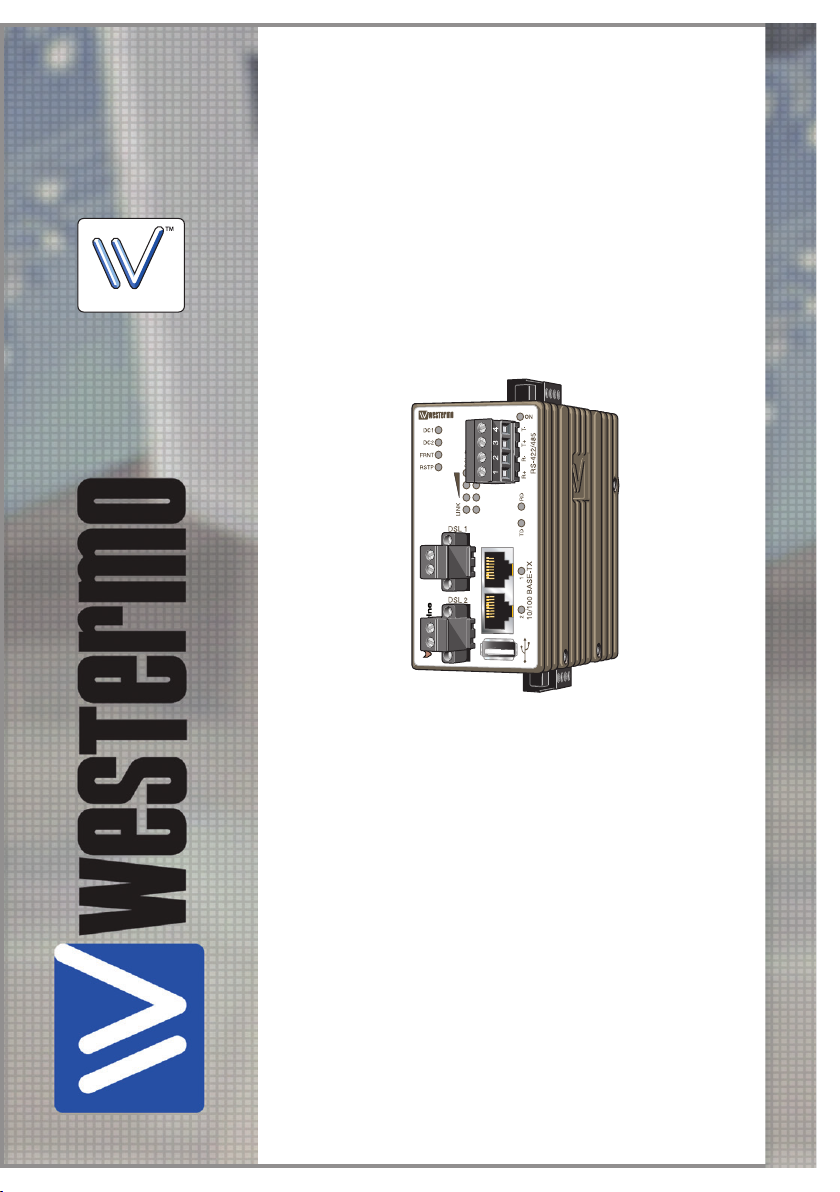
Industrial Ethernet Extender
www.westermo.com
Page 2

Software tools
Related software tools are available in the folder software tools under
technical support on the Westermo website.
License Information
This device contains public available software which is under the GPL license.
For more information see legal.pdf included with all firmware releases.
This product includes software developed by the OpenSSL Project for use in the
OpenSSL Toolkit. http://www.openssl.org
Legal information
The contents of this document are provided “as is”. Except as required by applicable
law, no warranties of any kind, either express or implied, including, but not limited to,
the implied warranties of merchantability and fitness for a particular purpose, are made
in relation to the accuracy and reliability or contents of this document. Westermo
reserves the right to revise this document or withdraw it at any time without prior
notice.
Under no circumstances shall Westermo be responsible for any loss of data or income
or any special, incidental, and consequential or indirect damages howsoever caused.
More information about Westermo can be found at the following Internet address:
http://www.westermo.com
2
6642-22511
Page 3

Safety
!
!
Before installation:
Read this manual completely and gather all information on the unit. Make sure
that you understand it fully. Check that your application does not exceed the safe
operating specifications for this unit.
This unit should only be installed by qualified personnel.
This unit should be built-in to an apparatus cabinet, or similar, where access is
restricted to service personnel only.
The power supply wiring must be sufficiently fused, and if necessary it must be
possible to disconnect manually from the power supply. Ensure compliance to
national installation regulations.
This unit uses convection cooling. To avoid obstructing the airflow around the unit,
follow the spacing recommendations (see Cooling section).
"Note that this unit can be connected to two different power sources."
Before mounting, using or removing this unit:
Prevent access to hazardous voltage by disconnecting the unit from power supply.
Warning! Do not open connected unit. Hazardous voltage may occur within this
unit when connected to power supply.
When this unit is operated at an ambient temperature above +60°C (+140°F),
forced ventilation is required to not exceed Touch Temperature Limits according
to UL/IEC/EN 60950-1. A recommended airflow 32CFM (61m3/h) located 17cm
(7") below the unit is a minimum requirement. To reduce the risk of fire, use only
No. 26 AWG or larger telecommunication line cord.
Care recommendations
Follow the care recommendations below to maintain full operation of unit and to fulfil
the warranty obligations.
This unit must not be operating with removed covers or lids.
Do not attempt to disassemble the unit. There are no user serviceable parts inside.
Do not drop, knock or shake the unit, rough handling above the specification may cause
damage to internal circuit boards.
Do not use harsh chemicals, cleaning solvents or strong detergents to clean the unit.
Do not paint the unit. Paint can clog the unit and prevent proper operation.
Do not expose the unit to any kind of liquids (rain, beverages, etc). The unit is not
waterproof. Keep the unit within the specified humidity levels.
Do not use or store the unit in dusty, dirty areas, connectors as well as other mechanical
part may be damaged.
If the unit is not working properly, contact the place of purchase, nearest Westermo
distributor office or Westermo Tech support.
A readily accessible disconnect device shall be incorporated external to the equipment.
This unit may have hot surfaces when used in high ambient temperature.
Maintenance
No maintenance is required, as long as the unit is used as intended within the specified
conditions.
6642-22511
3
Page 4
Agency approvals and standards compliance
Type Approval / Compliance
EMC EN 50121-4, Railway signalling and telecommunications apparatus
EN 55022, Information technology equipment.
Radio disturbance characteristics. Limits and methods of measurement
EN 55024, Electromagnetic compatibility – Immunity IT equipment
EN 61000-6-1, Immunity residential environments
EN 61000-6-2, Immunity industrial environments
EN 61000-6-3, Emission residential, commercial and light-industrial environments
EN 61000-6-4, Emission industrial environments
FCC part 15 Class A and Class B
IEC 62236-4, Railway signalling and telecommunications apparatus
Safety UL/IEC/EN 60950-1, IT-equipment
FCC Part 15.105 Notice:
This equipment has been tested and found to comply with the limits for a
Class B digital device, pursuant to Part 15 of the FCC Rules. These limits
are designed to provide reasonable protection against harmful interference
in a residential installation. This equipment generates, uses and can radiate
radio frequency energy and, if not installed and used in accordance with
the instructions, may cause harmful interference to radio communications.
However, there is no guarantee that interference will not occur in a
particular installation. If this equipment does cause harmful interference
to radio or television reception, which can be determined by turning
the equipment off and on, the user is encouraged to try to correct the
interference by one or more of the following measures:
… Reorient or relocate the receiving antenna
… Increase the separation between the equipment and receiver
… Connect the equipment into an outlet on a circuit different from that to
which the receiver is connected
… Consult the dealer or an experienced radio/TV technician for help.
4
6642-22511
Page 5
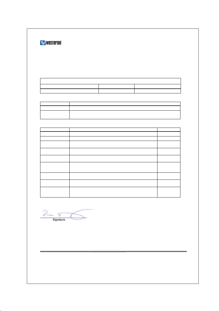
Declaration of Conformity
Org.nr/
th
Westermo Teleindustri AB
Declaration of conformity
The manufacturer
Herewith declares that the product(s)
Type of product Model Art no
Industrial Ethernet Extender DDW-142-485 3642-0310
is in conformity with the following EC directive(s).
No Short name
2004/108/EC Electromagnetic Compatibility (EMC)
2011/65/EU Restriction of the use of certain hazardous substances in electrical and
References of standards applied for this EC declaration of conformity.
No Title Issue
EN 61000-6-1 Electromagnetic compatibility – Immunity for residential environments 2007
EN 61000-6-2 Electromagnetic compatibility – Immunity for industrial environments 2005
EN 61000-6-3 Electromagnetic compatibility – Emission residential environments 2007
EN 61000-6-4 Electromagnetic compatibility – Emission for industrial environments 2007
EN 50121-4 Railway applications – Electromagnetic compatibility – Emission and
IEC 62236-4 Railway applications - Electromagnetic compatibility
EN 55024 Information technology equipment – Immunity characteristics
EN 55022 Information technology equipment – Radio disturbance characteristics –
EN 50581 Technical documentation for the assessment of electrical and
The last two digits of the year in which the CE marking was affixed: 15
Westermo Teleindustri AB
SE-640 40 Stora Sundby, Sweden
electronic equipment (RoHS)
immunity of the signalling and telecommunications apparatus
Emission and immunity of the signalling and telecommunications
apparatus
Limits and methods of measurement
Limits and methods of measurement
electronic products with respect to the restriction of hazardous
substances
+A1:2011
+A1:2011
2006
2008
2010
2010
2012
Pierre Öberg
Technical Manager
February 2015
20
Postadress/Postal address
S-640 40 Stora Sundby 016-428000 016-428001 52 72 79-4 5671-5550 556361-2604 Eskilstuna
Sweden Int+46 16428000 Int+46 16428001
Tel.
Telefax
Postgiro
Bankgiro Corp. identity number Registered office
6642-22511
5
Page 6
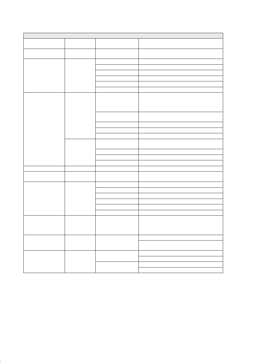
Type tests and environmental conditions
Electromagnetic Compatibility
Environmental
phenomena
Electrostatic discharge EN 61000-4-2 Enclosure Contact: ± 6 kV
Fast transients EN 61000-4-4 Power port ± 2 kV
Surge EN 61000-4-5 Power port L-L: ±0.5 kV, 2 Ω, 18 μF
Pulse magnetic field EN 61000-4-9 Enclosure 300 A/m
Radiated RF immunity EN 61000-4-3 Enclosure 20 V/m 80% AM, 1 kHz sine, 80 – 1000 MHz
Conducted RF
immunity
Voltage dips
and interruption
Radiated RF emission CISPR 16-2-3
Conducted RF
emission
Basic
standard
EN 55024 Ethernet ports
EN 61000-4-6 Power port 10 V, 80% AM, 1 kHz sine; 0.15 – 80 MHz
EN 61000-4-29 DC Power port 10, 20 and 5000 ms, interruption
ANSI C63.4
(FCC part 15)
CISPR 16-2-1 Power port Class B
Description Test levels
Air: ± 8 kV
Ethernet ports ± 2 kV
SHDSL ports ± 2 kV
RS-422/485 port ± 2 kV
Status out / Digital in ± 2 kV
Earth port ± 1 kV
L-E: ±0.5 kV, 12 Ω, 9 μF
L-E: ±2 kV, 42 Ω, 0.5 μF
Ethernet ports
(Shielded cable)
SHDSL ports L-E: ±2 kV, 42 Ω, 0.5 μF
RS-422/485 port L-E: ±2 kV, 2 Ω
Status out / Digital in L-E: ±2 kV, 42 Ω, 0.5 μF
(Shielded cable)
SHDSL ports L-E: ± 1kV, 40 Ω (15 + 25 Ω)
RS-422/485 port L-E: ± 1kV, 40 Ω (15 + 25 Ω)
Status out / Digital in L-E: ± 1kV, 40 Ω (15 + 25 Ω)
Ethernet ports 10 V, 80% AM, 1 kHz sine; 0.15 – 80 MHz
SHDSL ports 10 V, 80% AM, 1 kHz sine; 0.15 – 80 MHz
RS-422/485 port 10 V, 80% AM, 1 kHz sine; 0.15 – 80 MHz
Status out / Digital in 10 V, 80% AM, 1 kHz sine; 0.15 – 80 MHz
Earth port 10 V, 80% AM, 1 kHz sine; 0.15 – 80 MHz
Enclosure Class B
Ethernet ports Class B
L-L: ±1 kV, 42 Ω, 0.5 μF
L-E: ±2 kV, 2 Ω
L-E: ± 1kV, 15 Ω
12 V/m 80% AM, 1 kHz sine, 1000 – 2700 MHz
500 ms, 30% reduction
200 ms, 60% reduction
+20 above & –20% below rated voltage
Class B
Class B
Class B
6
6642-22511
Page 7

Electromagnetic Compatibility
Environmental
phenomena
Dielectric strength EN 60950-1 Power port to other
Environmental
Temperature EN 60068-2-1
Humidity EN 60068-2-27 Operating 5 to 95% relative humidity
Altitude Operating 2 000 m / 70 kPa
Service life Operating 10 years
Reliability prediction
(MTBF)
Vibration IEC 60068-2-64
Shock IEC 60068-2-27 Operating 6 ms 1000 m/s²
Bump IEC 60068-2-27 Operating 11 ms 100 m/s²
Packing
Enclosure material EN 60950-1 Zinc (fire enclosure)
Dimension W x H x D Without connectors 52.5 x 100 x 92 mm
Weight 0.8 kg
Degree of protection EN 60529 Enclosure IP 40
Cooling Convection
Mounting Enclosure Horizontal on 35 mm DIN-rail
Basic
standard
EN 60068-2-2
(random)
Description Test levels
isolated ports
Ethernet ports to all
other isolated ports
RS-422/485 port to all
other isolated ports
SHDSL ports to all
other isolated ports
Status out / Digital
in port to all other
isolated ports
Operating –40 to +70ºC (–40 to +158ºF)
Storage & Transport –40 to +85ºC (–40 to +185ºF)
Storage & Transport 5 to 95% relative humidity
Operating 435,000 hours (MIL-HDBK- 217F2, GB, 25°C)
Operating 5 – 20 Hz: 2 m²/s³
With connectors 52.5 x 100 x 111 mm
2000 Vrms 50 Hz 1 min
1500 Vrms 50 Hz 1 min
20 – 500 Hz: – 3 dB/oct
3 axis = 3 * 30 min
6 directions, 3 shocks/direction
6 directions, 100 shocks/direction
6642-22511
7
Page 8

Description
Functional description
The Wolverine DDW-142-485 allows effec tive Ethernet networks to be created over long
distances up to 15 km (9.3 mi) at data rates up to 15.3 Mbit/s on a single twisted pair
cable. By using two pairs “bonded” this rate can be doubled up to 30.4 Mbit/s. The integral
switch allows two Ethernet devices to be attached and an RS-422/485 port allows for a
legacy piece of equipment to be incorporated into the IP network.
The operating system in DDW-142-485 (WeOS) can deliver unique security functionality
for this class of product as well as allowing the DDW-142-485 to form part of a resilient
multimedia ring network using the Westermo FRNT protocol or industry standard STP/
RSTP. WeOS has been developed to provide industrial networking solutions and contains
amazing serial connectivity capability – from being able to simulate an old AT modem,
convert Modbus RTU to TCP or encapsulate serial data into an IP packet.
The DDW-142-485 is incredibly flexible and easy to use. A basic point-to-point or
multidrop network can be created without the need for any kind of configuration. If
however a more complex solution requires some kind of network configuration the
Web based setup is simple to use. A CLI interface is also provided making the unit easy
for networking professionals to quickly master. Once the system is configured an easy
solution is also available for the maintenance engineer – USB backup and restore means
that stored configurations can be automatically downloaded from a USB stick.
The DDW-142-485 is often used in applications on railways, roads or with utilities
where failure could result in significant costs. All Westermo products are designed with
high MTBF in mind to improve operational reliability and also give long service life. Even
features like the SHDSL diagnostics and management allow indication of line degradation
allowing planned main tenance. As the unit is designed for these applications Westermo
also ensure that testing is carried out to ensure the unit can operate at extremes of
temperature, EMC and vibration and still provide robust communications.
8
6642-22511
Page 9

Interface specifications
Power
Rated voltage 24 to 48 VDC
Operating voltage 19 to 60 VDC
Rated current 245 mA (405 mA) @ 24 VDC (with 500 mA USB load)
Rated frequency DC
Inrush current, I²t 10.6 mA²s @ 24 VDC
Startup current*) 2 x Rated current
Polarity Reverse polarity protected
Redundant power input Ye s
Isolation to All other
Connection Detachable screw terminal
Connector size 0.2 – 2.5 mm² (AWG 24 – 13)
Shielded cable Not required
* External supply current capability for proper start-up.
RS-422/485
Electrical specification EIA RS-422/485
Data rate 50 bit/s – 2 Mbit/s
Data format 7 or 8 data bits, Odd, even or none parity, 1 or 2 stop bits
Circuit type TNV-1
Transmission range Up to 1200 m / 0.74 mi, depending on data rate and cable
Isolation to Power, I/O realay output, I/O Digital input, SHDSL line,
Connection Detachable screw terminal
Connector size 0.2 – 2.5 mm² (AWG 24 – 12)
Shielded cable Not required, but recommended in railway installations close
Conductive housing Yes
* To minimise the risk of interference, a shielded cable is recommended when the cable is located inside 3 m
boundary or the cable is longer than 30 m and inside 10 m boundary to the rails and connected to this port.
124 mA (200 mA) @ 48 VDC (with 500 mA USB load)
24.7 mA²s @ 36 VDC
42.4 mA²s @ 48 VDC
Connect the unit using at least 18 AWG (0.75 mm²) wiring
(2 stop bits only when no parity is set).
type
Ethernet
to the rails.*
6642-22511
9
Page 10

Ethernet TX
Electrical specification IEEE std 802.3. 2005 Edition
Data rate 10 Mbit/s, 100 Mbit/s, manual or auto
Duplex Full or half, manual or auto
Circuit type TNV-1
Transmission range Up to 150 m, with CAT5e cable or better
Isolation to All other
Connection RJ-45, auto MDI/MDIX
Shielded cable Not required, except when installed in Railway applications as
signalling and telecommunications apparatus and located close
to rails.*
Conductive housing Ye s
Number of ports 2
* To minimise the risk of interference, a shielded cable is recommended when the cable is located inside 3 m
boundary to the rails and connected to this port.
The cable shield should be properly connected (360°) to an earthing point within 1 m from this port. This
earthing point should have a low impedance connection to the conductive enclosure of the apparatus cabinet,
or similar, where the unit is built-in. This conductive enclosure should be connected to the earthing system of an
installation and may be directly connected to the protective earth.
Console
Electrical specification LVTTL/LVCMOS-level
Data rate 115.2 kbit/s
Data format 8 data bits, none parity, 1 stop bit, no flow control
Circuit type SELV
Connection 2.5 mm jack, use Westermo cable 1211-2027
USB
Electrical specification USB 2.0 host interface
Data rate Up to 12 Mbit/s (full-speed mode)
Circuit type SELV
Maximum supply current 500 mA
Connection USB receptacle connector type A
10
6642-22511
Page 11

I/O / Relay output
Maximum voltage/current 60 VDC / 80 mA
Connect resistance Max 30 Ω
Isolation to All other
Connection Detachable screw terminal
Connector size 0.2 – 2.5 mm² (AWG 24 – 13)
I/O / Digital in
Maximum voltage / load current 60 VDC / 2 mA
Voltage levels Logic one >12 V, Logic zero <1V
Isolation to All other
Connection Detachable screw terminal
Connector size 0.2 – 2.5 mm² (AWG 24 – 13)
SHDSL
Electrical specification ITU-T G.991.2 Annex B
Data rate 32 kbit/s to 30.4 Mbit/s with bonding
Protocol EFM according to IEEE 802.3-2005
Transmission range According to ITU-T G.991.2 depending on line quality
Isolation to All other
Connection Detachable screw terminal
Connector size 0.2 – 2.5 mm² (AWG 24 – 13)
Shielded cable Not required
Number of ports 2
6642-22511
11
Page 12

Location of interface ports and LED’s
Power connection
(for more details see also page 10)
4-position Product marking Direction Description
1
2
3
4
This unit supports redundant power connection. The positive inputs are +DC1 and +DC2, the negative input for
both supplies are –COM. Connect the primary voltage (e.g. +24 VDC) to the +DC1 pin and return to one of the
–COM pins on the power input.
No. 1 +DC1 Input Supply voltage input DC1
No. 2 +DC2 Input Supply voltage input DC2
No. 3 -COM Input Common
No. 4 -COM Input Common
(for details see page 9 and 14)
LED Indicators
(for details
see page 15)
RS-422/485
Ethernet connection TX (2 ports)
(for more details see also page 10)
Position Direction* Description
No.1 In/Out Transmitted/Received data
No. 2 In/Out Transmitted/Received data
No. 3 In/Out Transmitted/Received data
No. 4 – Not Connected
No. 5 – Not Connected
No. 6 In/Out Transmitted/Received data
No. 7 – Not Connected
No. 8 – Not Connected
* Direction relative this unit.
USB
(for more details see also page 10)
Position Direction* Description
No.1 Out VBUS
No. 2 In/Out D–
No. 3 In/Out D+
I/O connection
(for details see
page 11 and 14)
SHDSL connection (for details see page 11 and 14)
No. 4 Out GND
Shield – Connected to protective earth
* Direction relative this unit.
12
6642-22511
Page 13

DDW-142-485 is equipped with internal termination that is configurable through software
No termination
in RS-422/485 mode. The following termination schemes are supported:
No termination
Terminate Rx Terminate Tx
Terminate Tx and Rx
Tx
Tx
Tx
Tx
RS-422
Rx
Rx
Rx
Termination
Rx
RS-485
When the unit is powered-off or during reboot, any internal termination will be
disconnected from the signal lines.
Note: There are no fail-safe biasing available for RS-422/485 signals.
Console port
(for more details see also page 10)
Position Direction* / description
No.1 GND
No. 2 Out / Tx
No. 3 In / Rx
* Direction relative to this unit.
I/O connection (for details see page 11 and 14)
Cable 1211-2027
Connection to console port
The console port can be used to connect to the CLI
(Command Line Interface).
The following steps needs to be taken
Bottom view
1. Connect the serial diagnostic cable to the console port
(use only Westermo cable 1211-2027).
2. Connect cable to your computer (USB port, if drivers are needed they can be downloaded
from our Web page).
3. Use a terminal emulator and connect with correct speed and format (115200, 8N1) to the
assigned port.
For more information about the CLI, see the WeOS management guide.
Accessories
Description Art no
Westermo console cable 1211-2027
6642-22511
13
Page 14

RS-422/485
Position
4
No. 1 R+ – In RS-422: Receive R+
3
2
No. 2 R– – In RS-422: Receive R–
1
No. 3
No. 4 T– T–/R– Out/In RS-422: Transmit
Signal
RS-422
(4-wire)
T+
RS-485
(2-wire)
Direction Description
T+/R+ Out/In
RS-422: Transmit
RS-485: Transmit/Receive
RS-485: Transmit/Receive
SHDSL
1
2
* Direction relative this unit.
Position Direction* Description
No.1 In/Out 2-wire Receive/Transmit SHDSL
No. 2 In/Out 2-wire Receive/Transmit SHDSL
I/O connection
4-position Product marking Direction Description
1
2
3
4
The Status output is a potential free, opto-isolated normally closed solid-state relay.
This can be configured to monitor various alarm events within the unit, see WeOS Management Guide.
An external load in series with an external voltage source is required for proper functionality.
For voltage/current ratings, see Interface Specification section.
No. 1 Status + Output Alarm relay (status) contact
No. 2 Status – Output Alarm relay (status) contact
No. 3 Digital in + Input Digital in +
No. 4 Digital in – Input Digital in –
Product
marking
T+
T–
The Digital in is an opto-isolated
digital input which can be used
to monitor external events.
For voltage/current ratings, see
Interface Specification section:
14
DDW-142-485
External
Load
1
Status
2
3
4
V
+
V
–
Digital In
6642-22511
Page 15

LED indicators
LED Status Description
ON OFF Unit has no power.
GREEN All OK, no alarm condition.
RED
FLASH Location indicator ("Here I am!"). Activated
DC1 OFF Unit has no power.
GREEN
RED Power failure on DC1.
DC2 OFF Unit has no power.
GREEN Power OK on DC2.
RED Power failure on DC2.
RSTP OFF RSTP disabled.
GREEN RSTP enabled.
BLINK Unit elected as RSTP/STP root switch.
FRNT OFF FRNT disabled.
GREEN FRNT OK.
RED FRNT Error.
BLINK Unit configured as FRNT focal point.
LNK
SHDSL ports
Link indicator
Port 1–2
SHDSL ports
Quality indicator
Port 1–2
RD OFF No serial data received.
TD OFF No serial data transmitted.
Copper ports
Port 1–2
OFF No DSL link.
GREEN DSL link established.
GREEN FLASH DSL link negotiation.
YELLOW Port alarm and no link.
All OFF No DSL link.
3 RED Signal to noise value below 3 dB.
1 GREEN Signal to noise value 3–5 dB.
2 GREEN Signal to noise value 6–9 dB.
3 GREEN Signal to noise value above 9 dB.
GREEN FLASH Serial data received.
GREEN FLASH Serial data transmitted.
YELLOW FLASH Indicate error on RS-422/485 bus.
OFF No link.
GREEN Link established.
GREEN FLASH Data traffic indication.
YELLOW Port alarm and no link. Or if FRNT, RSTP or
Alarm condition, or until unit has started
up. (Alarm conditions are configurable,
see ''WeOS Management Guide'').
when connected to IPConfig Tool, or upon
request from Web or CLI.
Power OK on DC1.
Or if FRNT or RSTP mode, port is blocked.
Unstable DSL link.
Marginal DSL link.
Normal DSL link.
Strong DSL link.
Link Aggregation mode, port is blocked.
6642-22511
15
Page 16

Mounting
This unit should be mounted on 35 mm DIN-rail, which is horizontally mounted inside an
apparatus cabinet or similar. It is recommended that the DIN-rail is connected to ground.
Snap on mounting, see figure.
Mounting DDW-142-485 with integrated DIN-clip:
Removal
Removing DDW-142-485 with integrated DIN-clip:
Press down the support at the back of the unit using
a screwdriver. See figure.
Cooling
This unit uses convection cooling. To avoid
obstructing the airflow around the unit, use minimum
spacing 25 mm (1.0") above/below and 10 mm (0.4")
left/right the unit.
Spacing is recommended for the use of unit in full
operating temperature range and service life. When
this unit is operated at an ambient temperature
above +60°C (+140°F), refer to the Safety warnings
on page 3.
16
10mm 10mm
6642-22511
Page 17

Getting Started
This product runs Westermo Operating System (WeOS) which provides several
management tools that can be used for configuration of the unit.
• IPConfig tool
This is a custom Westermo tool used for discovery of attached Westermo units.
• Web
Configuration of the unit using the web browser.
• CLI
Configuration of the unit via the Command Line Interface.
If the computer is located in the same subnet as the switch you can easily use a web
browser to configure the unit. Within the web you can configure most of the available
functions.
For advanced network settings and more diagnostic information, please use the CLI.
Detailed documentation is available in the chapter ”The Command Line Management
Tool” in the WeOS management guide.
Factory default IP address: 192.168.2.200
Netmask: 255.255.255.0
Gateway: Disabled
Note! If you are not sure about the subnet – consult your network administrator.
Configuration
Configure the unit via web browser
The unit can easily be configured via a web browser. Open the link http://192.168.2.200
in your web browser, and you will be prompted with a Login screen, where the default
settings for Username and Password are:
Username: admin
Password: westermo
Once you have logged in, you can use the extensive integrated help function describing
all configuration options. Two common task when configuring a new switch is to assign
appropriate IP settings, and to change the password of the admin account. The password
can be up to 64 characters long, and should consist of printable ASCII characters (ASCII
33-126); 'Space' is not a valid password character.
6642-22511
17
Page 18

Referring documents
Type Description Document number
Management Guide Westermo OS management guide
6101-3201
Cable factory reset on DDW-142-485
It is possible to set the unit to factory default settings by using a standard Ethernet RJ-45
cable.
1. Power off the unit and disconnect all cables.
2. Connect an Ethernet cable between Ethernet ports 1 and 2. The unit needs to be
connected directly by an Ethernet cable i.e., not via a hub or switch. Use a straight cable –
not a cross-over cable, when connecting the ports.
3. Power on the unit.
4. Wait for the unit to start-up. Control that the ON LED is flashing red. The ON LED
flashing indicates that the unit is now ready to be reset to factory default. You now
have the choice to go ahead with the factory reset, or to skip factory reset and boot
as normal.
• Go ahead with factory reset:
Acknowledge that you wish to conduct the factory reset by unplugging the Ethernet
cable. The ON LED will stop flashing. This initiates the factory reset process*, and
the unit will restart with factory default settings. When the switch has booted up, the
ON LED will show a green light, and is now ready to use.
• Skip the factory reset:
To skip the factory reset process, just wait for approximately 30 seconds (after the
ON LED starts flashing RED) without unplugging the Ethernet cable. The switch will
conduct a normal boot with the existing settings.
* Note Do not power off the unit while the factory reset process is in progress.
18
6642-22511
Page 19

Dimensions
Min 4mm
Max 7,5mm
Measurements are stated in millimeters.
52
±1
±1
100
96
±1
92
±1
±1
34
6642-22511
19
Page 20

Westermo • SE-640 40 Stora Sundby, Sweden
Tel +46 16 42 80 00 Fax +46 16 42 80 01
Sales Units
Westermo Data Communications
E-mail: info@westermo.com
www.westermo.com
China
sales.cn@westermo.com
www.cn.westermo.com
France
infos@westermo.fr
www.westermo.fr
Germany
info@westermo.de
www.westermo.de
For complete contact information, please visit our website at www.westermo.com/contact or scan the QR code
REV. C 6642-22511 2015-03 Westermo Teleindustri AB, Sweden – A Beijer Electronics Group Company
North America
info@westermo.com
www.westermo.com
Singapore
sales@westermo.com.sg
www.westermo.com
Sweden
info.sverige@westermo.se
www.westermo.se
United Kingdom
sales@westermo.co.uk
www.westermo.co.uk
Other Offices
 Loading...