

Page 1

User Guide
6621-2202
DDW-100
©
Westermo Teleindustri AB
Industrial Ethernet
SHDSL Extender
www.westermo.com
Page 2

Legal information
The contents of this document are provided “as is”. Except as required by applicable
law, no warranties of any kind, either express or implied, including, but not limited to,
the implied warranties of merchantability and fitness for a particular purpose, are made
in relation to the accuracy and reliability or contents of this document. Westermo
reserves the right to revise this document or withdraw it at any time without prior
notice.
Under no circumstances shall Westermo be responsible for any loss of data or income
or any special, incidental, and consequential or indirect damages howsoever caused.
More information about Westermo can be found at the following Internet address:
http://www.westermo.com
2
6621-2202
Page 3

Safety
!
!
Before using this unit:
Read this manual completely and gather all information on the unit. Make sure
that you understand it fully. Check that your application does not exceed the safe
operating specifications for this unit.
Hazardous voltage may occur within this unit when connected to power supply
or TNV circuits.
Prevent access to hazardous voltage by disconnecting the unit from power supply
and all other electrical connections.
Prevent damage to internal electronics from electrostatic discharges (ESD) by
discharging your body to a grounding point (e.g. use of wrist strap).
Before installation:
This unit should only be installed by qualified personnel.
This unit should be built-in to an apparatus cabinet, or similar, where access is
restricted to service personnel only.
The power supply wiring must be sufficiently fused, and if necessary it must be
possible to disconnect manually from the power supply. Ensure compliance to
national installation regulations.
This unit uses convection cooling. To avoid obstructing the airflow around the unit,
follow the spacing recommendations (see Installation section).
Care recommendations
Follow the care recommendations below to maintain full operation of unit and to fulfil
the warranty obligations.
This unit must not be operating with removed covers or lids.
Do not attempt to disassemble the unit. There are no user serviceable parts inside.
Do not drop, knock or shake the unit, rough handling above the specification may cause
damage to internal circuit boards.
Do not use harsh chemicals, cleaning solvents or strong detergents to clean the unit.
Do not paint the unit. Paint can clog the unit and prevent proper operation.
Do not expose the unit to any kind of liquids (rain, beverages, etc). The unit is not water-
proof. Keep the unit within the specified humidity levels.
Do not use or store the unit in dusty, dirty areas, connectors as well as other mechanical
part may be damaged.
If the unit is not working properly, contact the place of purchase, nearest Westermo dis-
tributor office or Westermo Tech support.
Maintenance
No maintenance is required, as long as the unit is used as intended within the specified
conditions.
6621-2202
3
Page 4

Agency approvals and standards compliance
Type Approval / Compliance
EMC EN 61000-6-2, Immunity industrial environments
EN 55024, Immunity IT equipment
EN 61000-6-3, Emission residential environments
FCC part 15 Class B
EN 50121-4, Railway signalling and telecommunications apparatus
IEC 62236-4, Railway signalling and telecommunications apparatus
Safety EN 60950-1, IT equipment
UL listed, UL 60950-1
CSA 22.2 No 60950-1-03
SHDSL ITU-T G.991.2, G.SHDSL standard
FCC Part 15.105 Notice: This equipment has been tested and found to comply with the
limits for a Class B digital device, pursuant to Part 15 of the
FCC Rules. These limits are designed to provide reasonable protection against harmful interference in a residential installation.
This equip ment generates, uses and can radiate radio frequency
energy and, if not installed and used in accordance with the
instructions, may cause harmful interference to radio communications. However, there is no guarantee that interference will not
occur in a particular installation. If this equipment does cause
harmful interference to radio or television reception, which can
be determined by turning the equipment off and on, the user is
encouraged to try to correct the interference by one or more of
the following measures:
… Reorient or relocate the receiving antenna
… Increase the separation between the equipment and receiver
… Connect the equipment into an outlet on a circuit different
from that to which the receiver is connected
… Consult the dealer or an experienced radio/TV technician
for help.
4
6621-2202
Page 5
Declaration of Conformity
Westermo Teleindustri AB
Declaration of conformity
The manufacturer
Herewith declares that the product(s)
Type of product Model Art no
SHDSL Ethernet bridge / DIN rail mounted DDW-100 3621-0002
is in conformity with the following EC directive(s).
No Short name
2004/108/EC Electromagnetic Compatibility (EMC)
References of standards applied for this EC declaration of conformity.
No Title Issue
EN 61000-6-1 Immunity for residential, commercial and light-
EN 61000-6-2 Immunity for industrial environments 2005
EN 61000-6-3 Emission standard for residential, commercial and
EN 61000-6-4 Emission standard for industrial environments. 2007
EN 50121-4 Railway applications – Electromagnetic compatibility
EN 55024 Information technology equipment – Immunity 1998
Westermo Teleindustri AB
SE-640 40 Stora Sundby, Sweden
industrial environments
light-industrial environments
– Emission and Immunity of the signalling and
telecommunications apparatus
2007
2007
2006
+ A1:2001
+ A2:2003
The last two digits of the year in which the CE marking was affixed: 08
Pierre Öberg
R&D Manager
16th April 2009
Postadress/Postal addres s
S-640 40 Stora Sundby 016-428000 016-428001 52 72 79-4 5671-5550 556361-2604 Eskilstuna
Sweden Int+46 16428000 Int+46 16428001
Tel.
Org.nr/
Telefax
Postgiro
Bankgiro
Corp. identity number Registered office
6621-2202
5
Page 6
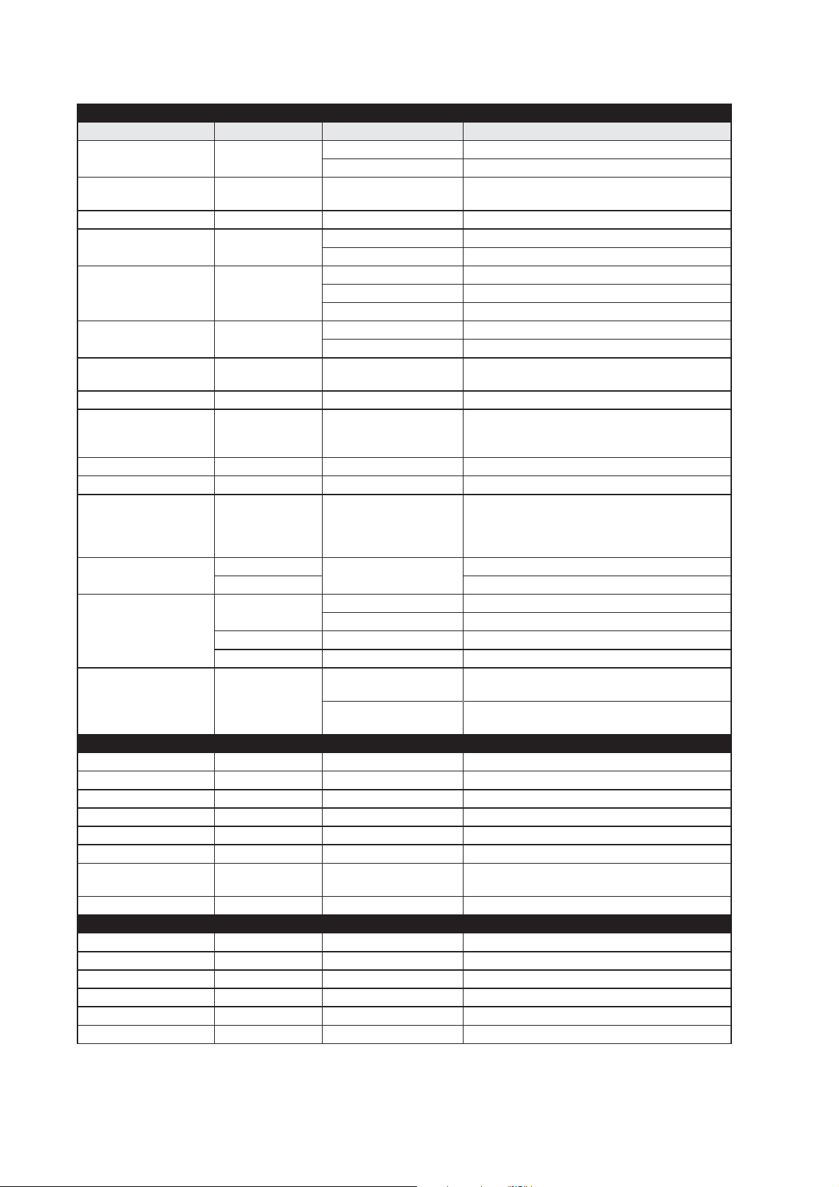
Type tests and environmental conditions
Electromagnetic Compatibility
Phenomena Test Description Test levels
ESD EN 61000-4-2 Enclosure contact ± 6 kV
Enclosure air ± 8 kV
RF field AM modulated EN 61000-4-3 Enclosure 10 V/m 80% AM (1 kHz), 80 – 1 000 MHz
20 V/m 80% AM (1 kHz), 80 – 2 700 MHz
RF field 900 MHz ENV 50204 Enclosure 20 V/m pulse modulated 200 Hz, 900 ± 5 MHz
Fast transient EN 61000-4-4 Signal ports ± 2 kV
Power ports ± 2 kV
Surge EN 61000-4-5 Signal ports unbalanced ± 2 kV line to earth, ± 2 kV line to line
Signal ports balanced ± 2 kV line to earth, ± 1 kV line to line
Power ports ± 2 kV line to earth, ± 2 kV line to line
RF conducted EN 61000-4-6 Signal ports 10 V 80% AM (1 kHz), 0.15 – 80 MHz
Power ports 10 V 80% AM (1 kHz), 0.15 – 80 MHz
Power frequency
magnetic field
Pulse magnetic field EN 61000-4-9 Enclosure 300 A/m, 6.4 / 16 μs pulse
Voltage dips and
interruption
Mains freq. 50 Hz EN 61000-4-16 Signal ports 100 V 50 Hz line to earth
Mains freq. 50 Hz SS 436 15 03 Signal ports 250 V 50 Hz line to earth
Voltage dips and inter-
ruption
Radiated emission EN 55022 Enclosure Class B
Conducted emission EN 55022 AC power ports Class B
Dielectric strength EN 60950 Signal port to other
Environmental
Temperature Operating –25 to +65ºC
Humidity Operating 5 to 95% relative humidity
Altitude Operating 2 000 m / 70 kPa
Service life Operating 10 year
Vibration IEC 60068-2-6 Operating 7.5 mm, 5 – 8 Hz
Shock IEC 60068-2-27 Operating 15 g, 11 ms
Packaging
Enclosure UL 94 PC / ABS Flammability class V-1
Dimension W x H x D 35 x 121 x 119 mm
Weight 0.2 kg
Degree of protection IEC 529 Enclosure IP 21
Cooling Convection
Mounting Horizontal on 35 mm DIN-rail
EN 61000-4-8 Enclosure 100 A/m, 50 Hz, 16.7 Hz & 0 Hz
EN 61000-4-11 AC power ports 10 & 5 000 ms, interruption
10 & 500 ms, 30% reduction
100 & 1 000 ms, 60% reduction
EN 61000-4-29 DC power ports 10 & 100 ms, interruption
10 ms, 30% reduction
10 ms, 60% reduction
+20% above & –20% below rated voltage
FCC part 15 Class B
Signal Ports Class B
FCC part 15 AC power ports Class B
EN 55022 DC power ports Class B
2 kVrms 50 Hz 1 min
isolated ports
Power port to other
isolated ports
Storage & Transport –25 to +70ºC
Storage & Transport 5 to 95% relative humidity
rms 50 Hz 1 min
3 kV
2 kV
rms 50 Hz 1 min (@ rated power <60 V)
2 g, 8 – 500 Hz
6
6621-2202
Page 7

Description
Functional description
SHDSL represents the best of several symmetric DSL technologies that have been combined into a single industry standard. The DDW-100 is designed as a transparent Ethernet
Extender (Ethernet Bridge) for 10/100BaseTX networks. It is transparent for multicast
addressing, VLAN packets, VPN pass-through for IPSec and for protocols like MODBUS/
tcp and Profinet.
SHDSL allows the re-use of existing twisted copper pair with data rates from 192 kbit/s
to 2.3 Mbit/s in both directions (Symmetric DSL), according to standard ITU-T G.991.2.
Based on the quality of the line and the communication speed, distances up to 10 km can
be achieved, this however depends of the quality of the line and cable characteristics.
This differs from application to application, therefore a unique feature is implemented
providing reliable-, normal-, or high speed mode.
Distance on /data rate without noise, cable type is AWG24, 0,2 mm
Tested distances with Cat 5 cables
192 kbit/s >6 km
384 kbit/s >6 km
512 kbit/s >6 km
768 kbit/s >6 km
1024 kbit/s >3 km
1280 kbit/s > 3 km
2048 kbit/s > 3 km
2304 kbit/s > 3 km
Distances up to 10 km at 192 kbit/s have also
2
been verified with a 1mm
cable.
Description of used nomenclature:
Noise margin:
The margin between signal and noise (dB)
2
CO/CPE:
CO (Central Office) answering central unit, the CO configures the CPE when establishing a connection. CPE (Customer Premises Equipment) is the unit that initiates the connection.
Annex A and B:
Annex A in ITU-T Rec. G.991.2 describes those specifications that are unique to SHDSL
systems operating under conditions such as those typically encountered within North
American networks.
Annex B in ITU-T Rec. G.991.2 describes those specifications that are unique to SHDSL
systems operating under conditions such as those typically encountered within European
networks.
6621-2202
7
Page 8

Getting started
The DDW-100 is easy to use and install, the units work in pairs, one as has to be configured as CO (Central Office) and one as CPE (Customer Premises Equipment). This configuration is made with DIP-switches situated under the lid of the DDW-100.
X Connect the SHDSL Line
There are two options for connecting the SHDSL line:
1) Connect the twisted pair to DSL screw terminal 1 and 2 (polarity independent)
situated atthe base of the DDW-100
2) Connect the line using the RJ-12 port on the front panel of the DDW-100.
Note! that these two connections are parallel, it is not possible to connect both
at the same time.
Y Connect the Ethernet Line
Connect Ethernet to the TX port onthe front of the DDW-100.
The factory settings for the DDW-100 is plug and play mode where TX port
is enabled for:
… Ethernet Auto-negotiation enabled.
… Auto MDI/MDI-X.
… Auto-polarity enabled.
The DDW-100 will automatically sense the data rate of the connected unit and cable
type.
Z Settings in the units
The units operate in pairs, one as CO (Central Office) and one as CPE
(Customer Premises Equipment). Factory setting in the DDW-100 is as CPE.
Note! Before connection and installation one of the connecting units have to be
reconfigured as a CPE, see DIP-switch S1:4.
Depending on the quality of the line and the distance there is possibility to select the
optimised speed.
This is done via DIP switches in the unit configured as CO. Factory default is 192 kbit/s.
When selecting higher speed note if the DSL link is established, if not, the selected speed
is too high for the distance.
8
6621-2202
Page 9

Diagnostic information:
The DDW-100 can display diagnostic information using a terminal. program
1) Connect a Westermo standard cable 1211-2026 (two metre 9-pole D-sub)
to the RS-232 interface located under lid.
1211-2026
RS-232
2) Open a terminal program with settings:
Data rate: 115.2 kbit/s
Data bits: 8
Stop bits: 1
Parity: None
Flow control: None
3) Type command DIAG or RUNDIAG
Information from DIAG command
• Software release
• DIP switch settings
• If the unit is configured as CO or CPE
• If the unit is configured for Annex A or Annex B
• DSL link state
• DSL data rate
• DSL noise margin
• Ethernet data rate
• Ethernet duplex
Information from RUNDIAG command
DSL Link state
DSL Datarate
DSL Noise Margin
Space aborts running diagnostics.
6621-2202
9
Page 10

Interface specifications
Power
Rated voltage 12 to 48 VDC
Operating voltage 10 to 60 VDC
Rated current 290 mA @ 12 VDC
140 mA @ 24 VDC
80 mA @ 48 VDC
Rated frequency DC
Inrush current, I
Startup current 0.6 A
2
t 0.098 A2s
peak
Polarity Reverse polarity protected
Redundant power input Yes
Isolation to All other
Connection Detachable screw terminal
Connector size 0.2 – 2.5 mm2 (AWG 24 – 12)
Shielded cable Not required
DSL Leased Line
Electrical specification ITU-T G.991.2 Annex B
Data rate 192 kbit/s to 2.304 Mbit/s
Protocol ITU-T G.991.2, Annex E Clear Channel Data
Transmission range According to ITU-T G.991.2 depending on the line quality:
Typical values using noise-free AWG26 Cables
2.3 Mbit/s reach > 3 km
192 kbit/s reach > 6 km
Protection Bidirectional transient surge arrestor
Isolation to All other
Galvanic connection to None
Connection Detachable screw terminal and RJ-12
Connector size 0.2 – 2.5 mm
2
(AWG 26 – 12)
Shielded cable Not required
Conductive housing No
Number of ports 1
10
6621-2202
Page 11

RS-232, Console port
Electrical specification RS-232/V.24
Data rate 115.2 kbit/s
Data format 8 data bits, none parity, 1 stop bit, no flow control
Circuit type SELV
Transmission range 15 m
Isolation to All other
Connection Westermo cable 1211-2066
Ethernet TX
Electrical specification IEEE std 802.3. 2000 Edition
Data rate 10 Mbit/s, 100 Mbit/s, manual or auto
Duplex Full or half, manual or auto
Circuit type SELV
Transmission range 100 m
Isolation to All other
Connection RJ-45 MDI or auto MDI/MDI-X
Shielded cable Not required, except when installed in Railway applications as
signalling and telecommunications apparatus and located close
to rails*
Conductive housing Isolated to all other circuits
Miscellaneous If Auto-Neg. is disabled then this interface will be set MDI, see below.
Number of ports 1
* To minimise the risk of interference, a shielded cable is recommended when the cable is located
inside 3 m boundary to the rails and connected to this port.
The cable shield should be properly connected (360°) to an earthing point within 1 m from this
port. This earthing point should have a low impedance connection to the conductive enclosure
of the apparatus cabinet, or similar, where the unit is built-in. This conductive enclosure should
be connected to the earthing system of an installation and may be directly connected to the
protective earth.
6621-2202
11
Page 12

Connections
Power connection
screw terminal
Position Description
No. 1 Common
No. 2 +VA
No. 3 +VB
No. 4 Common
DSL
DSL RJ-12 connector
Position Direction Description
No. 1 NC
No. 2 NC
No. 3 In/Out 2-wire Receive/
Transmit
SHDSL
No. 4 In/Out 2-wire Receive/
Transmit
SHDSL
No. 5 NC
No. 6 NC
SHDSL screw connector*
Position Direction Description
No. 1 In/Out 2-wire Receive/
Transmit
SHDSL
No. 2 In/Out 2-wire Receive/
Transmit
SHDSL
* Note that only one of the DSL connections
should be used.
The DDW-100 supports redundant power connection. The positive input are +VA and +VB, the negative input for both supplies are COM. The power is
drawn from the input with the highest voltage.
12
Ethernet connection (TX) (RJ-45 connector)
Contact Signal Name Direction Description/Remark
No.1 TD+ In/Out Transmitted/Received data
No. 2 TD– In/Out Transmitted/Received data
8
7
6
5
4
3
2
1
No. 3 RD+ In/Out Transmitted/Received data
No. 4
No. 5
No. 6 RD– In/Out Transmitted/Received data
No. 7
No. 8
Shield HF-connected
CAT 5 cable is recommended.
Unshielded (UTP) or shielded (STP) connector can be used.
6621-2202
Page 13

LED Indicators
LED Status Indication of
PWR OFF Unit has no power
ON Internal power
Slow flash Initialisation progressing
Fast FLASH Initialisation error
DSL * OFF Unit is unconnected
Flash 1 (200 ms) Unit is initializing DSL, only CO
Flash 2 (400 ms) Unit is in activation phase 1of DSL link
establishment
Flash 3 (1 s) Unit is in activation phase 2 of DSL link
establishment
ON Unit has established a DSL connection
LINK OFF No Ethernet link
ON Good Ethernet link
Flash Ethernet data is transmitted or received,
traffic indication
LED Status Indication of
SPD OFF 10 Mbit/s
ON 100 Mbit/s
DPX OFF HDPX, Half Duplex
ON FDPX, Full Duplex
* DSL LED indicator Description
Flash 1 (only in CO) Both CO and CPE have power and the line is connected
Flash 2 (both in CO and CPE) Synchronisation phase of DSL link
Flash 3 (both in CO and CPE) Activation phase of DSL link
ON (both in CO and CPE) Unit has established a DSL connection
6621-2202
13
Page 14
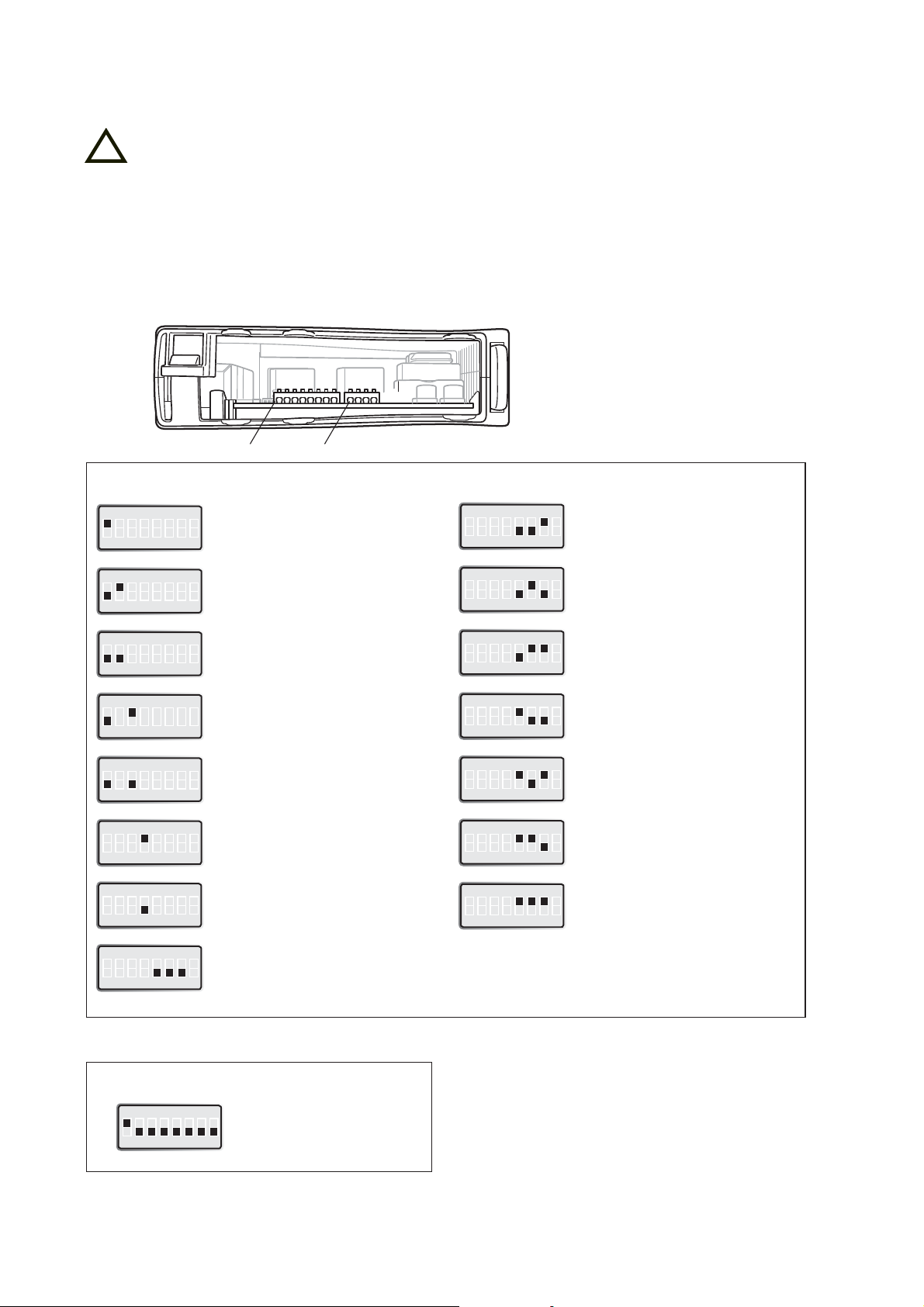
DIP-switch settings
!
Before DIP-switch settings:
Prevent damage to internal electronics from electrostatic discharges (ESD)
by discharging your body to a grounding point (e.g. use of wrist strap).
NOTE DIP-switch alterations are only effective after a power on.
A setting configured by any other method during normal operation, overrides
the DIP-switch setting. However, at power up, the DIP-switch settings have precedence over the setting configured by any other method.
S1 S2
S1* DIP-switch
ON
1 2 3 4 5 6 7 8
ON
1 2 3 4 5 6 7 8
ON
1 2 3 4 5 6 7 8
ON
1 2 3 4 5 6 7 8
ON
1 2 3 4 5 6 7 8
ON
1 2 3 4 5 6 7 8
ON
1 2 3 4 5 6 7 8
ON
1 2 3 4 5 6 7 8
Ethernet Auto-negotiation enabled.
Auto MDI/MDI-X.
10 Mbit/s auto-polarity enabled.
Speed 100 Mbit/s *
Speed 10 Mbit/s *
Full-Duplex, FDPX *
Half-Duplex, HDPX *
Central, CO
Remote, CPE
192 kbit/s
ON
384 kbit/s
1 2 3 4 5 6 7 8
ON
512 kbit/s
1 2 3 4 5 6 7 8
ON
768 kbit/s
1 2 3 4 5 6 7 8
ON
1.024 Mbit/s
1 2 3 4 5 6 7 8
ON
1.280 Mbit/s
1 2 3 4 5 6 7 8
ON
2.048 Mbit/s
1 2 3 4 5 6 7 8
ON
2.304 Mbit/s
1 2 3 4 5 6 7 8
* Configured as MDI • S1: 8 are not used
Factory settings
ON
S1
1 2 3 4 5 6 7 8
Auto-negotiation enabled, CPE, 192 kbit/s
14
6621-2202
Page 15
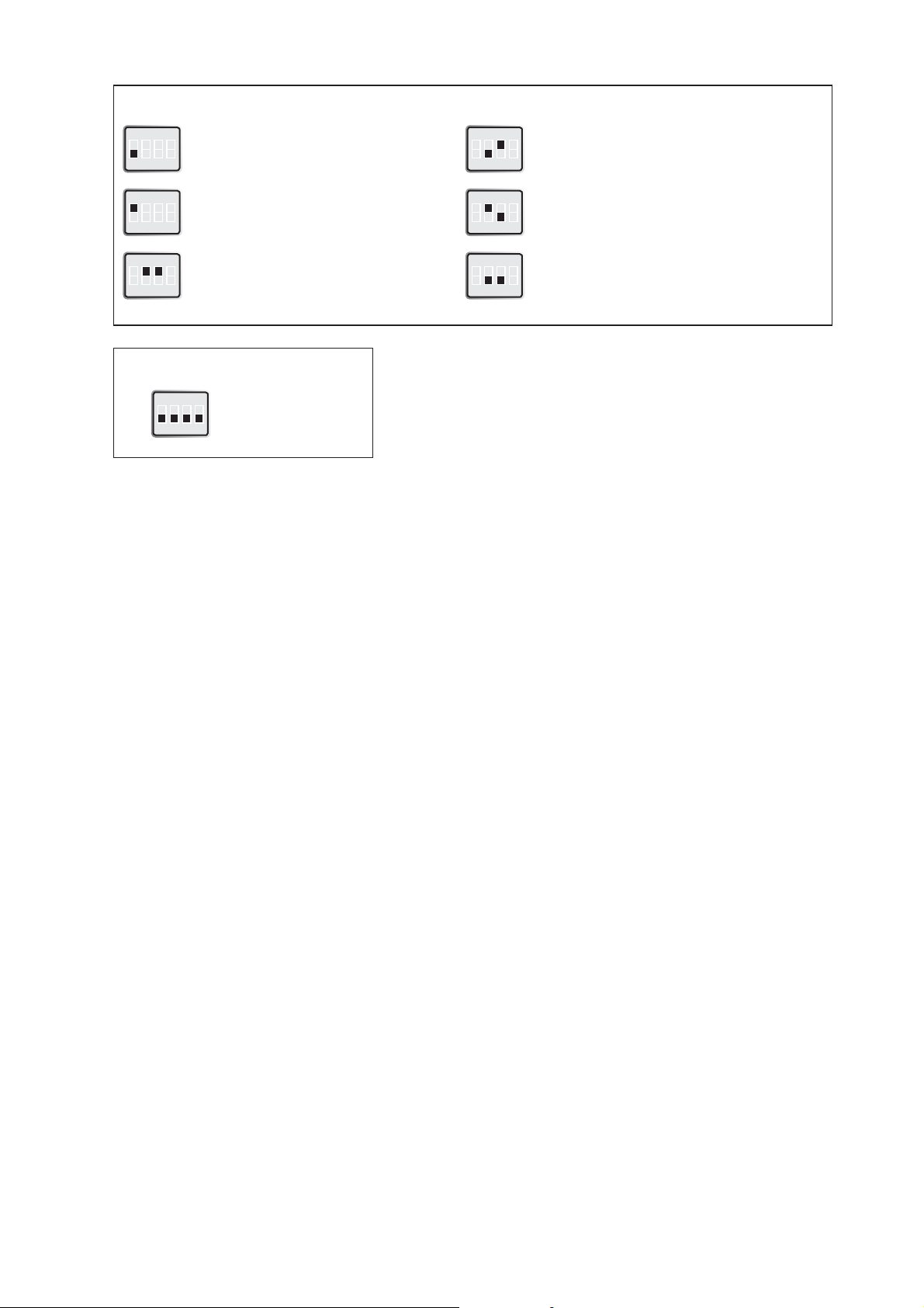
S2 DIP-switch
ON
1 2 3 4
ON
1 2 3 4
ON
1 2 3 4
Annex B Enabled
Reserved for Annex A
Reliable Mode,
Noise Margin = 6 dB
ON
1 2 3 4
ON
1 2 3 4
ON
1 2 3 4
High-Speed Mode,
Noise Margin = 0 dB
Normal Mode,
Noise Margin = 3 dB
Manual Speed Selected
(Locked Speed) see S1:5-7
Factory settings
ON
S2
1 2 3 4
Annex B enabled, manual peed selected
Description of normal, high-speed and reliable mode
With SW2:2, 3 the DDW-100 is set to reliable, high-speed or normal mode.
Choose mode depending on your application, if you wish to transmit large
amounts of non critical data, choose high-speed mode with a noise margin 0 dB.
If the data is critical, choose reliable mode.
When choosing one of reliable, high-speed or normal modes, the DDW-100 will
automatically set the highest possible speed according to the noise margin and
distance. The algorithm for sensing highest possible speed may result in a longer
connection time because several attempts have to be done to achieve a connection.
If the connection time is critical, it is possible to discover the connection speed
using the diagnostic port, then set the unit manually according to achieved
speed.
6621-2202
15
Page 16

Mounting
CLICK!
This unit should be mounted on 35 mm DIN-rail, which is
horizontally mounted inside an apparatus cabinet, or similar.
Snap on mounting, see figure.
Cooling
This unit uses convection cooling. To avoid obstructing the airflow around the unit, use the following spacing rules. Minimum
spacing 25 mm (1.0 inch) above /below and 10 mm (0.4 inches)
left /right the unit. Spacing is recommended for the use of unit
in full operating temperature range and service life.
* Spacing (left/right) recommended for
full operating temperature range
Removal
Press down the black support at the top of the unit. See figure.
10 mm *
(0.4 inches)
25 mm
25 mm
16
6621-2202
Page 17

Application
Block diagram
Diagn.
Port
4-& 8-pos. DIP Switch
Ethernet
Interface
Memory
Power
Isolation
Screw
Connector
SHDSL modem
DSL
Interface
Screw
Connector
Isolation
PHY
Isolation
RJ-45
Connector
LED
Power
SHDSL
Link
RJ-12
Connector
DDW-100 as an transparent Ethernet extender
Ethernet Ethernet
6621-2202
17
Page 18

Page 19

Page 20

Westermo Teleindustri AB • SE-640 40 Stora Sundby, Sweden
Phone +46 16 42 80 00 Fax +46 16 42 80 01
E-mail: info@westermo.se
Westermo Web site: www.westermo.com
Subsidiaries
Westermo Data Communications AB
Svalgången 1
SE-724 81 Västerås
Phone: +46 (0)21 548 08 00 • Fax: +46 (0)21 35 18 50
info.sverige@westermo.se
Westermo Data Communications Ltd
Talisman Business Centre • Duncan Road
Park Gate, Southampton • SO31 7GA
Phone: +44(0)1489 580-585 • Fax.:+44(0)1489 580586
E-Mail: sales@westermo.co.uk
Westermo Data Communications GmbH
Goethestraße 67, 68753 Waghäusel
Tel.: +49(0)7254-95400-0 • Fax.:+49(0)7254-95400-9
E-Mail: info@westermo.de
Westermo Teleindustri AB have distributors in several countries, contact us for further information.
Westermo Data Communications S.A.R.L.
9 Chemin de Chilly 91160 CHAMPLAN
Tél : +33 1 69 10 21 00 • Fax : +33 1 69 10 21 01
E-mail : infos@westermo.fr
Westermo Data Communications Pte Ltd
2 Soon Wing Road #08-05
Soon Wing Industrial Building
Singapore 347893
Phone +65 6743 9801 • Fax +65 6745 0670
E-mail: earnestphua@westermo.com.sg
REV.F 6621-2202 2010-04 Westermo Teleindustri AB, Sweden
 Loading...