

Page 1
User Guide
6623-2231
ADSL-350
Westermo Teleindustri AB
©
Industrial ADSL Router
www.westermo.com
Page 2

2
6623-2231
Legal information
The contents of this document are provided “as is”. Except as required by applicable
law, no warranties of any kind, either express or implied, including, but not limited to,
the implied warranties of merchantability and fitness for a particular purpose, are made
in relation to the accuracy and reliability or contents of this document. Westermo
reserves the right to revise this document or withdraw it at any time without prior
notice.
Under no circumstances shall Westermo be responsible for any loss of data or income
or any special, incidental, and consequential or indirect damages howsoever caused.
More information about Westermo can be found at the following Internet address:
http://www.westermo.com
Page 3

3
6623-2231
Safety
!
!
Before installation:
Read this manual completely and gather all information on the unit. Make sure that
you understand it fully. Check that your application does not exceed the safe operating specifications for this unit.
This unit should only be installed by qualified personnel.
This unit should be built-in to an apparatus cabinet, or similar, where access is
restricted to service personnel only.
The power supply wiring must be sufficiently fused, and if necessary it must be
possible to disconnect manually from the power supply. Ensure compliance to
national installation regulations.
This unit uses convection cooling. To avoid obstructing the airflow around the unit,
follow the spacing recommendations (see Cooling section).
Before mounting, using or removing this unit:
Prevent access to hazardous voltage by disconnecting the unit from power supply.
Warning! Do not open connected unit. Hazardous voltage may occur within this
unit when connected to power supply.
Care recommendations
Follow the care recommendations below to maintain full operation of unit and to fulfil
the warranty obligations.
This unit must not be operating with removed covers or lids.
Do not attempt to disassemble the unit. There are no user serviceable parts inside.
Do not drop, knock or shake the unit, rough handling above the specification may cause
damage to internal circuit boards.
Do not use harsh chemicals, cleaning solvents or strong detergents to clean the unit.
Do not paint the unit. Paint can clog the unit and prevent proper operation.
Do not expose the unit to any kind of liquids (rain, beverages, etc). The unit is not water-
proof. Keep the unit within the specified humidity levels.
Do not use or store the unit in dusty, dirty areas, connectors as well as other mechanical
part may be damaged.
If the unit is not working properly, contact the place of purchase, nearest Westermo dis-
tributor office or Westermo Tech support.
Fibre connectors are supplied with plugs to avoid contamination inside the optical port.
As long as no optical fibre is mounted on the connector, e.g. for storage, service or
transportation, should the plug be applied.
Maintenance
No maintenance is required, as long as the unit is used as intended within the specified
conditions.
Page 4

4
6623-2231
Agency approvals and standards compliance
Type Approval / Compliance
EMC EN 55024, EN 55024 A1, EN 55024 A2,
Safety EN 60950-1, IT equipment
Electromagnetic compatibility – Immunity IT equipment
EN 55022, EN 55022 A1, Information technology equipment.
Radio disturbance characteristics. Limits and methods of measurement
Page 5

5
6623-2231
Declaration of Conformity, ADSL-350
Westermo T eleindustri AB
Declaration of conformity
Org.nr/
Postadress/Postal address
Tel.
Telefax
Postgiro
Bankgiro Corp. identity number Registered office
S-640 40 Stora Sundby 016-428000 016-428001 52 72 79-4 5671-5550 556361-2604 Eskilstuna
Sweden Int+46 16428000 In t+46 16428001
The manufacturer Westermo Teleindustri AB
SE-640 40 Stora Sundby, Sweden
Herewith declares that the product(s)
Type of product Model Art no
ADSL router /
Modem
ADSL 350 3623-0301
is in conformity with the following EC directive(s).
No Short name
1999/5/EC Radio and Telecommunications Terminal Equipment
References of standards applied for this EC declaration of conformity.
No Title Issue
EN 301489-1 ElectroMagnetic compatibility and Radio spectrum Matters
(ERM) - ElectroMagnetic Compatibility (EMC) standard for
radio equipment and services – Part 1
2011(1.9.2)
EN 60950-1 Information technology equipment. Safety. General
requirements
2006
+A11:2009
+A12:2011
+A1:2010
The last two digits of the year in which the CE marking was affixed: 12
Pierre Öberg
Technical Manager
2nd July 2012
Page 6

6
6623-2231
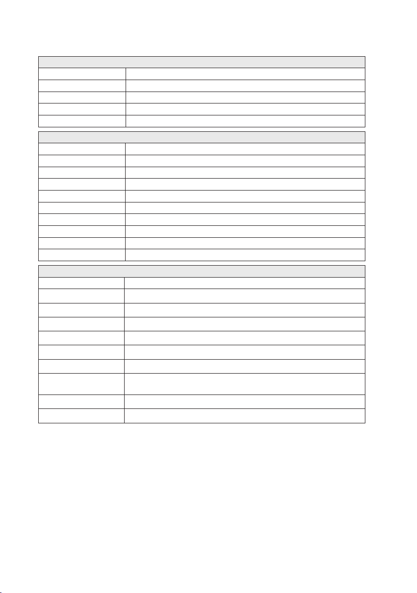
Type tests and environmental conditions
Phenomena Test Description Test levels
ESD EN 61000-4-2 Enclosure contact ± 4 kV (crit A)
RF field AM modulated IEC 61000-4-3 Enclosure 10 V/m (crit A)
Fast transient EN 61000-4-4 Signal ports ± 1 kV (crit A)
Surge EN 61000-4-5 Ethernet ports ± 1 kV (direct) (crit A)
RF conducted EN 61000-4-6 All ports 10 V/m, (crit A)
Radiated emission EN 55022 Enclosure Class B
Conducted emission EN 55022 AC power ports Class B
Temperature Operating –25 to +70°C (–13 to +158°F)
Humidity Operating 0 to 90% relative humidity non
Altitude Operating 2000 m / 70 kPa
Service life Operating 10 year
Dimension W x H x D 53 x 103 x 97 mm
Weight 0.40 kg
Degree of protection IEC 529 Enclosure IP 40
Cooling Convection
Mounting Horizontal on 35 mm DIN-rail
Enclosure air ± 8 kV (crit A)
(80 – 2700 MHz)
Power ports ± 2 kV (crit A)
Power ports
DC power ports Class B
Ethernet ports Class B
Storage & Transport –40 to +85°C (–40 to +185°F)
Storage & Transport 0 to 90% relative humidity non
± 0.5 kV (line to earth) (crit A)
± 0.5 kV (line to line) (crit A)
(0.15 – 80 MHz)
condensing.
condensing.
(2.08 x 4.05 x 3.81 in)
Page 7

7
6623-2231
Description
92,3
±0,5
4,4
±0,5
36
±0,5
103
±0,5
53
±0,5
Remote access removes boundaries, eliminates the need for time consuming site visits
and provides a network infrastructure suitable for today's “always-on” society. The ADSL350 is an industrially designed ADSL broadband router built to cope with harsh environments and the characteristics of industrial applications. The unit supports a wide range of
ADSL-standards and has support for long lines.
Most devices today comes equipped with an Ethernet port for communications, therefore
the ADSL-350 has a built-in two port Ethernet switch. For legacy connectivity the unit
also features one RS-232-port to provide multiple connection possibilities for both new
and legacy replacement installations. Designed to be installed on a DIN rail all connectors
and LEDs have been positioned in the front of the unit, facing the user for easy access
and fast status feedback. With the wide power input range the unit can be powered from
10 to 60 VDC and has low power consumption.
The cyber security features of the ADSL-350 prevent unauthorized access and secure the
communication for Internet-enabled applications. The easy to use firewall filters incoming traffic, allowing only approved packets to pass through. To inter-connect units with
each other securely over the Internet multiple VPN technologies are supported, including
IPsec and OpenVPN.
Upgrading legacy solutions to become IP-enabled can prove both costly and tedious
therefore the ADSL-350 includes a wide feature set for various legacy applications including both modem replacement methods as well as serial to Ethernet conversion. If there
are applications that require extra attention Westermo's extensive experience from
over 35 years within industrial data communications and over 5 years of industrial ADSL
expertise will be available to assist you.
Dimensional drawing
(mm)
Page 8
8
6623-2231
Interface specifications
Power
Rated voltage 12 – 48 VDC
Operating voltage 10 – 60 VDC
Rated current (max) 520 mA @ 12 VDC
Start-up current (max) 5500 mA @ 12 VDC
Rated frequency DC
RS-232
Electrical specification EIA RS-232
Data rate 300 bit/s – 115.2 kbit/s
Data format 7 or 8 data bits, Odd, even or none parity, 1 or 2 stop bits
Protocol Transparent, optimised by packing algorithm
Circuit type SELV
Transmission range 15 m / 49 ft
Connection 9 pin D-sub female
Shielded cable Not required
Conductive housing Yes
Number of ports 1
Ethernet TX
Electrical specification IEEE std 802.3. 2005 Edition
Data rate 10 Mbit/s, 100 Mbit/s, manual or auto
Duplex Full or half, manual or auto
Circuit type SELV
Transmission range 100 m / 328 ft
Isolation to All other
Connection RJ-45 auto MDI/MDIX
Shielded cable Not required, except when installed in Railway applications as signalling
Conductive housing Yes
Number of ports 2
* To minimise the risk of interference, a shielded cable is recommended when the cable is located inside 3 m
boundary to the rails and connected to this port.
The cable shield should be properly connected (360º) to an earthing point within 1 m from this port.
This earthing point should have a low impedance connection to the conductive enclosure of the apparatus
cabinet, or similar, where the unit is built-in. This conductive enclosure should be connected to the earthing
system of an installation and may be directly connected to the protective earth.
and telecommunications apparatus and located close to rails.*
Page 9

9
6623-2231
DSL
Data rate 30 Mbit Downlink, 3 Mbit Uplink
Protocol LLC/VC-MUX encap Ethernet, PPPoA, PPPoE, IPoA
Connection RJ-11
Shielded cable Not required, except when installed in Railway applications as
signalling and telecommunications apparatus and located close
to rails.*
Number of ports 1
Standard Annex
ITU-T G.992.1 (ADSL) A (non overlap)
ITU-T G.992.3 (ADSL2) A, I, L, M (non overlap)
ITU-T G.992.5 (ADSL2+) A, I, M (non overlap)
ANSI T1.413 N/A
* To minimise the risk of interference, a shielded cable is recommended when the cable is located inside 3 m
boundary or the cable is longer than 30 m and inside 10 m boundary to the rails and connected to this port.
Page 10

10
6623-2231
Connections
ADSL-350
DSL
DSL
5
1
9
6
1
2
Factory default
reset switch
Ethernet TX Connections
(RJ-45 connector) LAN1-2
Position Direction Description
1 In/Out TD+
2 In/Out TD–
3 In/Out RD+
4 – Not Connected
5 – Not Connected
6 In/Out RD–
7 – Not Connected
8 – Not Connected
Router Serial Port (DCE Female)
Position Name Direction Description
1 DCD Out Data Carrier Detect
2 RxD Out Receive Data
3 TxD In Transmit Data
4 DTR In Data Terminal Ready
5 SG – Signal Ground
6 DSR Out Data Set Ready
7 RTS IN Request to Send
8 CTS Out Clear to Send
9 RI Out Ring Indicator
Power connector
2-position Product marking Direction Description
DSL
(for details,
see page 11)
Led indicators
(for details,
see next page)
Protective
Earth
No. 1 + Input Supply voltage input DC
No. 2 – Input Common
Page 11

11
6623-2231
LED Indicators
DSL
LED Status Description
STS
Status
PWR
Power
SIG
Connection
status
DSL
ADSL link
status
STS LED – Status indicator
The status indicator reports the health of the unit. In normal operation the indicator will
be green, however, if a fault is detected, either at boot-up or during normal operation, the
indicator will light red. When the unit is first switched on or is reset the indicator will
first light red, then flash red in sequence with the SIG LED, this is normal behavior during
boot-up and does not indicate a fault.
Configuring a VPN connection in the ADSL-350 and activating the service will cause the
STS LED to be lit GREEN but FLASH RED every third (3) second to indicate that no
peer is connected on the VPN. The feature of the VPN status in the STS LED makes it
easy for staff to see whether or not the VPN connection is working without having to
login to the device.
RED Indicates a fault, except during boot-up
RED FLASH Indicates a fault, except during boot-up
GREEN All OK
GREEN & ONE RED FLASH All OK but no VPN peer connected
OFF Unit has no power
GREEN All OK
RED No ADSL connection configured or
GREEN / RED
GREEN 1 BLINK
GREEN 2 BLINKS
GREEN 3 BLINKS
GREEN 4 BLINKS
GREEN 5 BLINKS
GREEN 6 BLINKS
OFF No ADSL connection
GREEN FLASH Negotiating with the provider DSLAM
GREEN All OK, ADSL link established
network fault
Network connection fault
Connection link speed indication
1 Low
3 Normal
6 High (≥24 Mbit/s)
PWR LED – Power indicator
The power indicator will light green when power is applied. If the indicator does not light
when power is applied check the power supply voltage and connections, refer to see
page 8 for details.
SIG LED – Connection status
The Signal Strength Indicator reports the state of the ADSL network connection. The
ADSL sync speed is indicated by the number of green flashes of the indicator within
an indicator period. Each indicator green flash will be followed by a short off time, an
extended off time indicates the end of the indicator period.
Page 12

12
6623-2231
An indicator period starts with a green flash followed by up to 5 additional flashes, then
ADSL-350
DSL
DSL
an extended off time, the cycle will then repeat. The maximum number of flashes in an
indicator period is 6.
The indicator may be red during the extended off time following the green flashes indicating an ADSL network connection fault. The LED will be lit solid red if an ADSL connection cannot be established.
When the unit is first switched on, or is reset, the indicator will first light red, then flash
red in sequence with the STS LED, this is normal behavior during boot-up and does not
indicate a fault.
DSL LED – ADSL link status
The DSL LED reports the status of the connection to the network. When powered up
the indicator will be off, the indicator will then flash green whilst the unit tries to negotiate the link with the provider DSLAM, once successfully connected to the provider the
indicator will light green to indicate that everything is ready and functioning on the ADSL
link level.
Factory Default Reset Switch
The reset switch is used to restore the configuration of the ADSL-350 to the factory
default settings (for details about the default settings see the Getting started section).
The switch is accessed through a small hole, adjacent to the PWR and STS LEDs, labeled
C on the front of the unit.
To reset the configuration:
• Power down the unit.
• Using a suitable tool depress the reset switch.
• Power up the unit ensuring the switch remains depressed for approximately 5 seconds
after power is applied. The STS LED will flash twice (2) times to indicate a reset.
• Once the unit has booted-up it will use the default settings.
Note: Using the factory default reset switch will erase all existing configuration settings
and restore the factory default settings.
Factory default reset switch
Page 13

13
6623-2231
Protocols and Functionality
Ethernet Technologies
ADSL Technologies
Serial Port Technologies
IP Routing, Firewall, VPN
and Cyber Security
Manageability
For more information on the features and functionality, please refer to the Management Guide on
the product website.
IEEE 802.3 for 10BaseT
IEEE 802.3u for 100BaseTX
Layer-2 QoS
IEEE 802.1p Class of Service
ITU-T G.992.1 ADSL (Annex A (non overlap))
ITU-T G.992.2 ADSL Lite (Annex A (non overlap))
ITU-T G.992.3 ADSL2 (Annex A, I, L, M (non overlap))
ITU-T G.992.5 ADSL2+ (Annex A, I, M (non overlap))
RFC2684 Bridged LLC and Bridged VC-MUX ATM encap. (ADSL)
ADSL2++ Quad spectrum downstream and double upstream
TR-067 Compliance
Dying Gasp support
ITU K.21 Support
Rate adaptive modem at 32 Kbps steps
ATM Layer with traffic shaping QoS support (UBR, CBR, VBR-rt,VBR-nrt)
AAL5 – AAL
F5 OAM Loopback/Send and receive
RFC2364 PPPoA client support
RFC2516 PPPoE client support
RFC2225 / RFC1577 Classical IP Support
PAP/CHAP/MS-CHAP for Password Authentication support
RS-232
Serial Over IP (Serial Extender and Virtual Serial Port)
Modem emulation
AT command interpreter
MODBUS
DNP3
Static IP routing
Dynamic IP routing
• RIPv1/v2
VRRP
GRE
Stateful inspection Firewall / ACL, NAT, Port Forwarding
25 x IPsec VPN, PSK & X.509
1 x L2TP client
1 x PPTP client
1 x OpenVPN / SSL VPN client
RADIUS
PPP Dial in/Dial out
Management tools
• Web-interface (HTTP and HTTPS)
• Command Line Interface (CLI) via SSHv2 and TELNET
• SNMPv1/v2c
Syslog (log files)
SNTP (NTP client)
DHCP client
DHCP server
DDNS (Dynamic DNS update client)
Page 14

14
6623-2231
Getting started
Default Network Settings
IP address (Ethernet ports) 192.168.2.200
Netmask (Ethernet ports) 255.255.255.0
Username admin
Password westermo
Power Supply
The ADSL-350 requires a DC power source in the voltage range of 10 to 60 VDC.
The unit is designed to self protect from permanent damage if the voltage exceeds
60 VDC or if reverse polarity is applied. The router may need to be returned for service
if this occurs. The router can also be damaged if there is any potential difference between
the chassis-ground, RS-232 signal ground, power (–) input, or antenna shield.
Before connecting any wiring, ensure all components are earthed to a common ground
point. An external isolator will be required if a positive earth power supply is used.
Step-by-step guide
to configure an ADSL-connection using the web-interface
ADSL
connection (RJ-11)
PC/Ethernet
connection (RJ-45)
Power Connection
Step 1 – Power-up the unit and wait for it to become ready
Connect the ADSL-350 to the DSL-network using the RJ-11. Then connect an RJ-45 cable
from one of the two Ethernet-ports to your PC, and finally connect the unit to an appropriate PSU and power it up. As soon as the STS LED is lit GREEN the unit is ready to be
configured, it should take about 30 seconds.
Page 15

15
6623-2231
Step 2 – Configure your PC
Make the following changes on your PC.
IP address 192.168.2.100*
Netmask 255.255.255.0
Gateway 192.168.2.200
Preferred DNS server 192.168.2.200
* Can be any address in the 192.168.2.0-255-range except 192.168.2.200.
Note! If you are unsure or unable to change the above – consult your network
administrator.
Step 3 – Accessing the unit
Start a web browser on your PC and type in the following address
http://192.168.2.200
Step 4 – Login screen
After step 3 an authorization box will popup which asks for a username and a password.
Please type in the following
Username admin
Password westermo
Step 5 – Welcome screen
You have now successfully logged into the unit and reached the Status-page that lists the
current status of the unit and the services.
Note! The Line Status may indicate a fault, as in the screenshot, but this is completely
normal since there isn’t any connection configured yet. Follow the steps below to configure your ADSL connection.
Page 16

16
6623-2231
Step 6 – Change to the ADSL setup menu
Start by clicking on ADSL in the top-menu followed by Connection in the sub-menu.
Then click on Add new connection.
Step 7 – Find your ADSL connection settings
Refer to the table below to find your settings for the ADSL connection. If you cannot find
your specific connection in the table, please contact your local provider and ask them
about the settings. Sometimes you also get the information in your “start-package” from
the provider. If you are unable to find these settings, please do not hesitate to contact
Westermo Support, see the last page for details in your country, or have a look on the
Westermo website.
Use the VPI, VCI, ATM Enc. and Connection Type settings to configure your ADSL connection in the next steps.
ADSL Settings per country (Verified July 2012)
Country Provider VPI VCI ATM enc. Connection type
Austria Telecom Austria 8 48 VC MUX PPPoA
Ireland Eirecom 8 35 LLC PPPoE
Italy Libero 8 35 VC MUX PPPoA
Italy Telecom Italia 8 35 VC MUX PPPoA
Italy Tiscali 8 35 VC MUX PPPoA
Italy Tele2 8 35 VC MUX PPPoA
Netherlands KPN (MXStream) 8 48 VC MUX PPPoA
Netherlands KPN (Business) 2 32 VC MUX PPPoA
Netherlands Bbned (Fast) 0 35 VC MUX PPPoA
Netherlands BBNed 0 35 LLC Mac encapsulation routing / DHCP
Netherlands Versatel 0 32 VC MUX PPPoA
Netherlands Telfort 0 34 LLC Mac encapsulation routing / DHCP
Sweden TeliaSonera 8 35 LLC Mac encapsulation routing / DHCP
United Kingdom British Telecom (BT) 0 38 VC MUX PPPoA
Note! The default settings of the unit are UK & BT (marked in bold in the table above).
Page 17

17
6623-2231
Step 8 – Configure the ADSL connection – part 1
Using your specific provider details you may need to change the VPI, and VCI settings
on this first screen.
When you have verified that the settings match, please click on Next.
Step 9 – Configure the ADSL connection – part 2
(Connection Type and Encapsulation)
On this page you use your Connection Type and ATM enc. settings. As before,
make sure these settings match the ones you received from your provider.
Step 10 – Configure the ADSL connection – part 3
(Extra settings depending on Connection Type)
In our example, using PPPoA, the following page is presented. If you are using another
Connection Type you will see a different page here.
Your provider will give you any username, password, and/or service name you might
need.
Page 18

18
6623-2231
Complete the required fields for your connection and then click on Submit.
The ADSL-350 will then reconfigure the ADSL settings of the unit and set up
the connection. You can follow the process by either looking at the SIG and
DSL LEDs on the physical unit, or look at the ADSL Status page by clicking
on the top level menu Status, followed by the ADSL sub-menu.
Step 11 – Verify the Internet-connection
As the above screenshot shows, the ADSL-350 is now connected to the Internet and
has successfully received an IP-address from the provider. From the attached PC you
should now be able to access the Internet, verify by going to your favorite website
(e.g. westermo.com) using your browser on the PC.
The ADSL-350 is now ready to be used!
Note! The ADSL-350 is by default cyber secured by the built-in firewall, meaning that
any connections originating from the Internet is stopped in order to protect against
some of the online threats. Should you need to open up the firewall this can easily be
done by going to the top-menu Firewall, and then clicking on the Access Control
sub-menu. For more details about the firewall and how to setup other scenarios, please
refer to the Management Guide on the product website.
Page 19

19
6623-2231
Additional configuration guides
In this section a few common use-cases and their configuration is listed. For more information about protocols and features of the ADSL-350 please refer to the Management
Guide on the Westermo product website.
Changing the default password
Westermo strongly recommend users to change the default password of the unit in
order to increase the security. Navigate to the top-level menu System followed by the
sub-menu Administration, once there, please click on the little pen-icon next to the field
Edit users and passwords.
After clicking on the pen, a new page will be shown where the password of both the
admin and guest* user. Unless the ADSL-350 should use a Radius server to centrally
authenticate the login, the Radius configuration details can be ignored.
Type in the current password of the user and then select a new secure password and
type it into both the New password field as well as the Confirm password field. Then
click on Update to activate the changes.
Note! The guest-user-account is by default disabled; once the password is set for the
guest user it becomes active.
Page 20

20
6623-2231
Changing the LAN IP address
Sometimes the default IP address range does not fit the current IP plan of the application.
Changing the LAN IP address of the ADSL-350 is very easy. Start by navigating to the
top-menu Network, followed by the sub-menu LAN.
In the IP Address input box the default IP is listed, 192.168.2.200. Change this to the new
IP address that the unit requires and, if needed, also update the Netmask, then click on
Update. The ADSL-350 will then display a page with a link to the new IP address and then
change its IP, no reboot is required.
Note! Make sure the PC network settings are updated accordingly so that it is possible
to access the new ADSL-350 IP address.
Enabling the DHCP server
For easy administration the ADSL-350 can act as a DHCP server to any LAN connected
devices. The DHCP server allows clients on the local network to be automatically allocated IP addresses from the ADSL-350. The unit will also provide the clients with network settings like their default route and DNS servers.
To enable the DHCP server please navigate to the top-menu Network, followed by the
sub-menu LAN. By default the DHCP server is disabled but if enabled it will be configured to serve IP addresses in the range 192.168.2.210 through 192.168.2.240, and the
Default and Maximum lease times have been set to 1440 minutes. Should these values be
consistent with the network that the ADSL-350 is connected to, the DHCP server can
be enabled by ticking the Enabled field followed by clicking the Update button.
If the default settings do not match the application network, make the appropriate changes,
and remember to tick the Enabled box. Then click Update and the DHCP server is started.
For those that may need to configure static IP addresses based on attached devices MAC
addresses, the ADSL-350 will display a section for that once the server is started, i.e. after
ticking the Enabled box and clicking on Update.
Note! The DHCP server will automatically use the LAN IP address of the ADSL-350 as
the default gateway for clients.
Page 21

21
6623-2231
Configure LAN clients to use the ADSL-350 as their gateway
The ADSL-350 will act as a gateway for connections destined to the Internet. The default
configuration will provide Network Address Translation and firewalling to protect clients
on the local network.
In order to configure any LAN clients to use the ADSL-350 as their gateway the following to methods can be used;
If the clients have a DHCP address allocated by the ADSL-350, they will have learned the
necessary settings. No further configuration is needed.
Or, if clients have static IP addresses, set their default route and DNS server to the IP
address of the ADSL-350, by default 192.168.2.200.
The ADSL-350 sometimes changes the ADSL IP address /
Our provider cannot offer us a fixed IP address
In some applications there is a need to connect to the ADSL-350 from the Internet,
either via a VPN (recommended) or by opening up the firewall for some specific services
/ ports. Either way, the connecting systems / devices need to know where to connect
to and if the service provider keeps changing the ADSL IP address that the unit receives
from their servers it can become a nightmare to constantly update any settings in the
systems / devices. Luckily there is a solution to this that is very commonly used on the
Internet and it is called Dynamic DNS, or DDNS.
It works in roughly the following way; once the ADSL-350 notices that it has a new
IP-address on the ADSL interface it will send an update to the DDNS service provider
that will update the domain name that have been associated with the unit.
The most common DDNS provider is called Dyn™ (earlier DynDNS ™) –
http://dyn.com – but there are others out there as well. The ADSL-350 supports a
few different providers that can be found on the configuration page of DDNS.
Register an account with the provider of choice and then configure a domain
name with that provider to be used on the ADSL-350. Then it is time to configure
the ADSL-350 to use the domain name so that it can be accessed instead of the
direct IP address, removing the need to actually know the IP address.
Navigate to the top-menu Network followed by the sub-menu DNS.
For the purpose of this example the following details will be used;
Domain name server.mine.nu
Username user
Password pass
Page 22

22
6623-2231
Finish and activate the settings by clicking on Update, the DDNS client will now
track the changes of the ADSL interface of the ADSL-350 and update the domain
server.mine.nu should the unit get a new IP address.
Note! Even though any changes usually are updated / replicated quite quickly, there can
be issues, e.g. at the DDNS service provider, that prevents updates, or introduces delays.
For more critical applications a fixed IP address may prove more reliable, or the use of
other methods to guarantee connectivity. Feel free to contact Westermo Support should
you have any questions about this, or refer to the Westermo website.
How can the ADSL-350 be configured from the Internet?
In some scenarios the user might want to configure the ADSL-350 from the Internet,
either by accessing a DDNS name, or using a fixed IP address from a PC on the Internet.
Since the ADSL-350 is cyber secured by a firewall by default, the user must first allow
traffic from the Internet trying to access the web-interface / webserver of the ADSL-350
to pass through.
Westermo strongly recommends any user opening up the firewall to change the default
password of the ADSL-350 before doing so.
To open the ADSL-350 for access to the web-interface from the Internet just navigate to
the top-menu Firewall followed by the sub-menu Access Control.
Page 23

23
6623-2231
In this view some of the most common services are listed and their current firewall
Internet
ADSL 350 router
192.168.2.100
status. In our example we wanted the unit to respond to incoming requests destined to
the web-interface on the ADSL interface IP (DSL-1). Just tick the Allow tickbox and then
click on Update. The settings are activated immediately and the ADSL-350 can now be
accessed from the Internet.
How to access a device connected to the LAN or Serial port of the ADSL-350
/ How to open up a port in the firewall.
For any type of communication with devices connected to the LAN ports, or the Serial
port, Westermo strongly recommends the use of Virtual Private Networks (VPNs). Refer
to the product website at Westermo for application notes and the detailed Management
Guide for more information about VPNs.
Sometimes there may be a need for a simpler, but less secure approach, either for testing or for non-critical applications. With the use of portforwarding a connecting system /
device can use the IP address of the ADSL-350 to communicate with devices attached to
the LAN, or Serial, side of the unit.
In our example an HMI is connected to the LAN port of the ADSL-350, and has been
configured with the ADSL-350 as its default gateway;
The HMI has a built-in webserver on TCP port 80, our goal is to access the HMI’s
webserver from the Internet on our laptop.
Page 24

24
6623-2231
Start by configuring a DDNS account, and a domain name, for this example the
server.mine.nu name will be used. Once DDNS is configured in the ADSL-350 it is
time to create a firewall rule that allows traffic coming from the Internet to the
ADSL-350 on a specific port to be forwarded to the HMI. For the purpose of this
example the incoming port that the PC will be using is 12345.
Navigate to the top-menu Firewall followed by the sub-menu Port Forwards and then
click on Add new port forward. In the screenshot below the information above has
been used to create a port forward to the HMI. The user on the laptop would open his
browser and type in the domain name followed by a colon and then the custom port, e.g.
http://server.mine.nu:12345.
Once Update is clicked the port forward is active. If the HMI has been configured
properly it would now be accessible.
Note! If the connected LAN device, e.g. the HMI or PLC, does not have the possibility
to set a default gateway the use of 1:1 NAT can be used. For more information about
how to achieve this please refer to the Management Guide.
Page 25

25
6623-2231
10mm 10mm
ADSL-350
DSL
DSL
Mounting
This unit should be mounted on 35 mm DIN-rail, which is horizontally mounted inside an
apparatus cabinet or similar. Snap on mounting, see figure.
Mounting the ADSL-350 with integrated DIN-clip:
Cooling
The router should be mounted in a
clean and dry location, protected from
water, excessive dust, corrosive fumes,
extremes of temperature and direct
sunlight. Allow sufficient ventilation to
ensure adequate cooling of the router.
Page 26

Page 27

Page 28

Westermo • SE-640 40 Stora Sundby, Sweden
Tel +46 16 42 80 00 Fax +46 16 42 80 01
E-mail: info@westermo.com
www.westermo.com
Sales Units
Sweden
Westermo Data Communications
Svalgången 1, Vallbyinstitutet, 724 81 Västerås
Tel: +46 (0) 21 548 08 00 • Fax: (0) 21 35 18 50
info.sverige@westermo.se • www.westermo.se
United Kingdom
Westermo Data Communications
Talisman Business Centre
Duncan Road, Park Gate, Southampton. SO31 7GA
Tel: +44 (0) 1489 580 585 • Fax: +44 (0) 1489 580 586
sales@westermo.co.uk • www.westermo.co.uk
Germany
Westermo Data Communications
Goethe Strasse 67
DE-68753 Waghäusel
Tel: +49 (0) 7254 95400-0 • Fax: +49 (0) 7254-95400-9
info@westermo.de • www.westermo.de
Austria
Westermo Data Communications
Tel: +43 (0) 72030 3920 • Fax: +43 (0) 2235 86131
info@westermo.at • www.westermo.at
France
Westermo Data Communications
Bat. A, 9 Chemin de Chilly
FR-91160 Champlan
Tel: +33 1 69 10 21 00 • Fax: +33 1 69 10 21 01
infos@westermo.fr • www.westermo.fr
Singapore
Westermo Data Communications
2 Soon Wing Road #08-05,
Soon Wing Industrial Building
Singapore 347893
Tel: +65 6743 9801 • Fax: +65 6745 0670
sales@westermo.com.sg • www.westermo.com.sg
North America
Westermo Data Communications
939 N. Plum Grove Road, Suite F,
IL 60173 Schaumburg, USA
Tel: +1 847 619 6068 • Fax: +1 847 619 66 74
info@westermo.com • www.westermo.com
Taiwan
Westermo Data Communications
F2, No. 188, Pao-Chiao Rd. Shing-Tien City,
Taipei 23145
Tel: +886 2 8911 1710
sales.cn@westermo.com • www.cn.westermo.com
China
Westermo Data Communications
2F Building B
No.1618 Yishan Road
Shanghai 201103
Tel: +86 21 6145 0400 • Fax: +86 21 6145 0499
sales.cn@westermo.com • www.cn.westermo.com
Westermo Teleindustri AB have distributors in several countries , contact us for further information.
REV.A 6623-2231 2012-06 Westermo Teleindustri AB, Sweden – A Beijer Electronics Group Company
 Loading...