

Page 1

Installation and Operator Handbook Introduction
CONTENTS
Page
1 INTRODUCTION
1.1
1.2 P
OVERVIEW
HYSICAL ARRANGEMENT
............................................................................................................................................................2
...................................................................................................................................4
1.2.1 General........................................................................................................................................................4
1.2.2 Configuration Options.................................................................................................................................6
1.3 S
PECIFICATIONS
...................................................................................................................................................8
1.3.1 General Specifications.................................................................................................................................8
1.3.2 Power Consumption....................................................................................................................................8
1.3.3 Environmental Specifications......................................................................................................................8
1.3.4 Applicable Standards...................................................................................................................................9
LIST OF FIGURES
F
F
F
IGURE
IGURE
IGURE
1-1 F
1-2 R
1-3 B
RONT VIEW
EAR VIEW
LOCK DIAGRAM
- DRB-25..................................................................................................................................2
- DRB-25 ...................................................................................................................................3
- DRB-25..........................................................................................................................5
LIST OF TABLES
T
1-1 DRB-25 O
ABLE
T
1-2 DRB-25 V
ABLE
T
1-3
ABLE
T
1-4 G
ABLE
T
1-5 P
ABLE
T
1-6 E
ABLE
T
1-7 A
ABLE
PERATIONAL CONFIGURATIONS
OICE INTERCONNECT CONFIGURATION OPTIONS
DRB-25 P
ENERAL SPECIFICATIONS
OWER CONSUMPTION
NVIRONMENTAL SPECIFICATIONS
PPLICABLE STANDARDS
ROGRAMMING AND DIAGNOSTIC CONFIGURATION OPTIONS
....................................................................................................................................8
................................................................................................................................9
..............................................................................................................................8
.................................................................................................................8
.....................................................................................................6
...........................................................................7
...........................................................7
AMX–MA–00651 Issue 0.02 (USA)
1
Page 2
Installation and Operator Handbook Introduction
1 INTRODUCTION
1.1 OVERVIEW
This document describes the DRB-25 Dual Radio Base Station system installation procedures, configuration
and operational details.
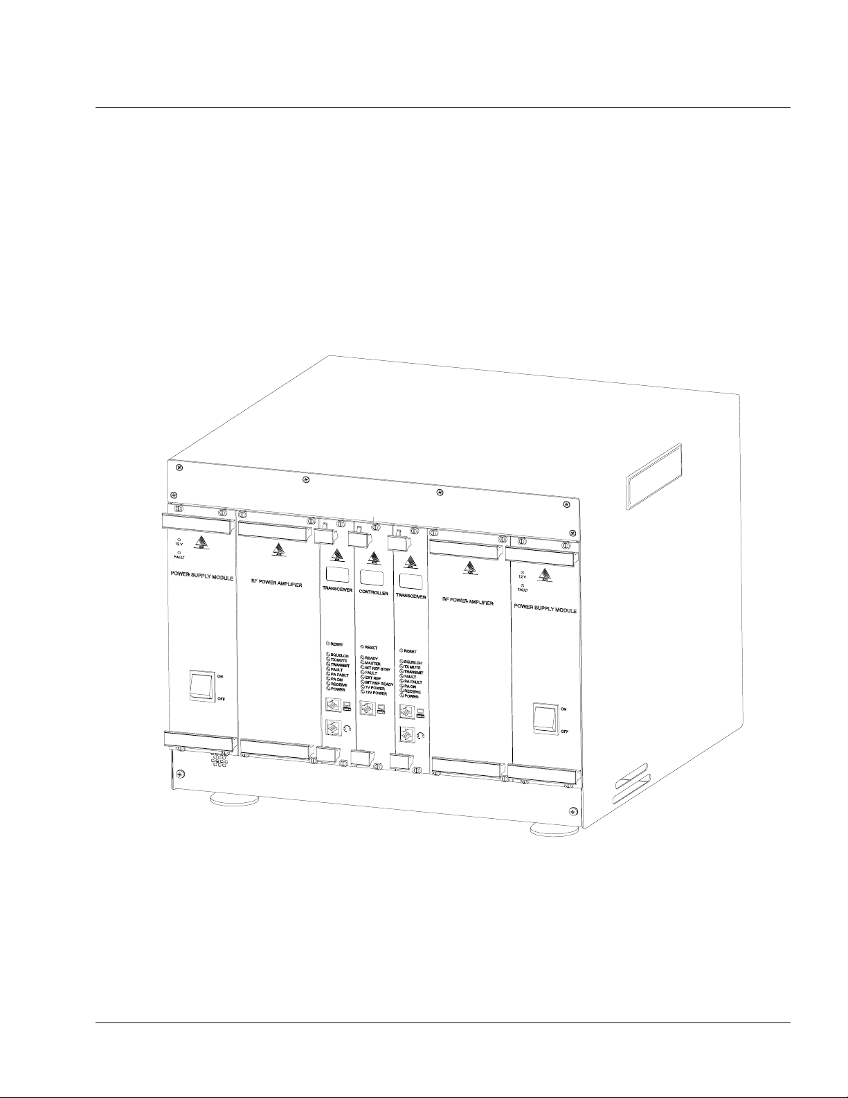
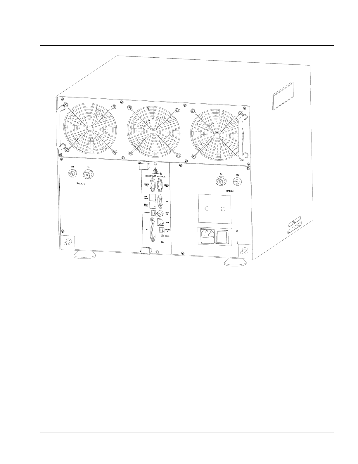
The DRB-25, shown in Figure 1-1 and Figure 1-2, is a compact, multi-mode transceiver package which
provides users with one or two analog or APCO Project 25 digital radio channels. The small size and high
level of flexibility of the DRB-25 make it an ideal solution for any organization starting out on the digital
migration path.
AMX–MA–00651 Issue 0.02 (USA)
Figure 1-1 Front View - DRB-25
2
Page 3
Installation and Operator Handbook Introduction
Figure 1-2 Rear View - DRB-25
The DRB-25 provides one or two independent radios in a single package. Each radio can be used as a base
station or a repeater, and may be configured to support both APCO Project 25 compliant digital subscribers as
well as providing backwards compatibility to analog users. This means that existing mobile radio equipment
need not be immediately retired.
Each radio may be configured to provide an analog interface (2 wire with loop or ground start or 4 wire with
E & M signaling) to the public switched telephone network (PSTN), to a private branch exchange (PBX), or
to existing tone based remote control units.
The DRB-25 provides the key elements of an APCO Project 25 RF Sub-system including the air interface
(Um), interfaces for telephone and PBX interconnect (Et) and host data systems (Ed). Support for Ethernet
based network management, digital consoles and the APCO Project 25 fixed station interface (Ef) will be
available as software upgrades.
AMX–MA–00651 Issue 0.02 (USA)
3
Page 4

Installation and Operator Handbook Introduction
The DRB-25 provides the following features:
• Automatically and concurrently supports the digital mobile and FM analog radios (TIA/EIA 603
including CTCSS selective calling).
• VHF (136-174 MHz) or UHF (400-470 MHz) frequency bands.
• 60 W or 125 W RF output.
• Configurable as singl e or dual channel with any mix of frequency bands a nd output power levels.
• 512 programmable channels per radio, with each channel programmable as APCO Project 25 digital or
TIA/EIA 603 analog.
• Programmable channel scan of up to eight channels.
• Optional RS232, RS485, Ethernet and general purpose I/O interfaces.
• Optional 2 wire or 4 wire + E&M wire line interfaces for remote control or telephone interconnect.
• Compatible with industry standard tone remote control consoles.
• Compatible with Microwave Links using 4 Wire and E & M signaling.
• User friendly Windows configuration and diagnost i c software for local or re mote configuration.
• Self test diagnostic routines.
• 240/110 VAC or 12, 24 or 48 VDC versions.
• Available as a standard 19” rack mount sub-rack, as a desktop unit or housed in a secure floor mount
cabinet.
In addition, the DRB-25:
• Enables a gradual migration from analog to digital terminals, or from one frequency band to another,
communicating across-mode and across-bands while the migration is taking place.
• Provides link radio functions to other base stations or repeaters for geographically remote areas.
• Enables upgrade from a single-channel to dual-channel at low cost.
• Provides a low cost upgrade path from the dual-channel to a multi-channel base station.
1.2 PHYSICAL ARRANGEMENT
1.2.1 General
The DRB-25 is a completely self-contained cabinet unit housing all the components necessary to support one
(single-channel) or two (dual-cha nnel) radio configurations. The basic housing is provided with feet for
desktop use and may optionally be supplied with mounting brackets for rack-mounting. Alternatively the
entire unit may be installed in a secure cabinet.
Integral to the housing are the system power supplies, fans and airflow control for cooling of modules and a
common backplane into which the Transceiver, Controller and Interface Modules are plugged . A singlechannel DRB-25 requires one Controller Module and the following plug-in modules:
AMX–MA–00651 Issue 0.02 (USA)
4
Page 5
Installation and Operator Handbook Introduction
• One Transceiver Module.
• One Power Amplifier Module.
• One Power Supply Module.
• One Interface Module (Optional - depending on external interfaces).
A dual-channel DRB-25 requires one Controller Module and the following plug-in modules:
• Two Transceiver Modules.
• Two Power Amplifier Modules.
• Two Power Supply Modules.
• One Interface Module (Optional - depending on external interfaces).
A single-channel DRB-25 can be easily and inexpensively converted to a dual-channel DRB-25 by the
installation of the additional modules.
The DRB-25 may be configured for AC or DC power sources, or as AC power with DC revert in the case of
AC power failure.
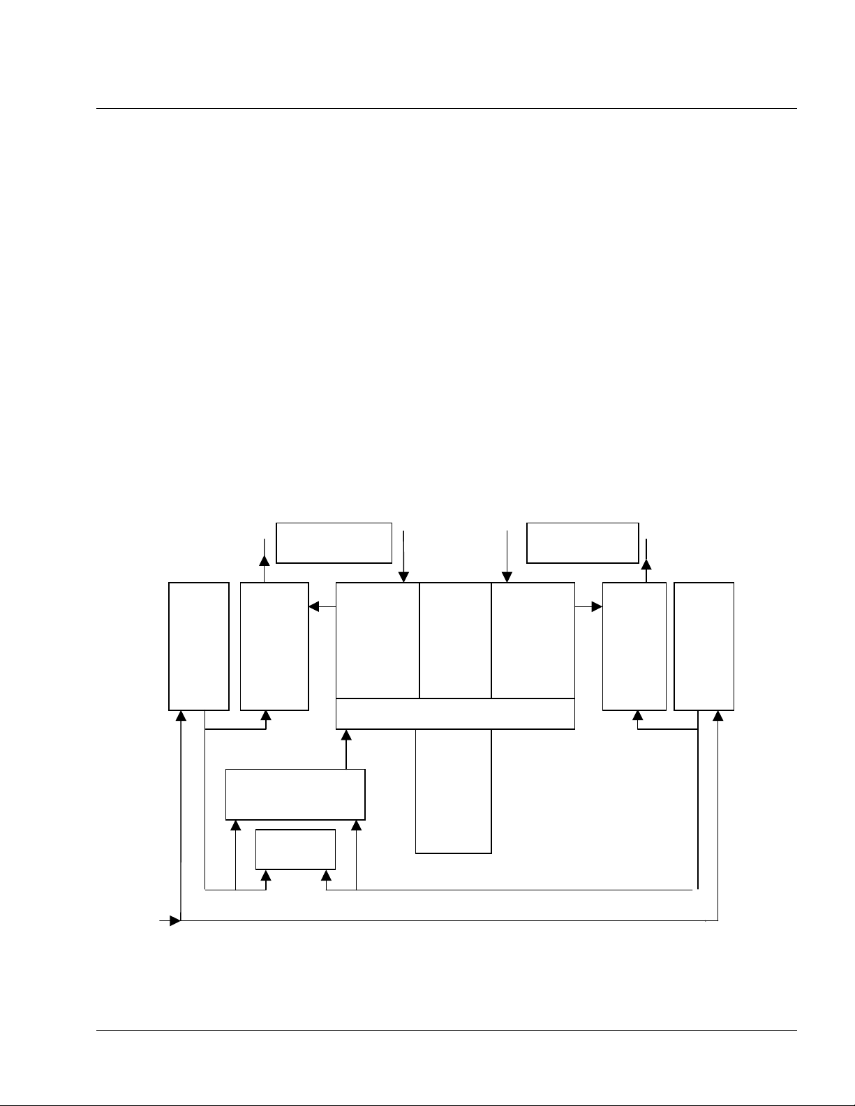
A block diagram of a DRB-25 is shown in Figure 1-3.
Power
Supply
Module
AC/DC Power
Radio 1Antenna
Connections
Power
Amplifier
Module
System Power
Supply
Fan
Module
Transceiver
Module
Controller
Module
Backplane
Interface
Module
(external
interfaces)
Radio 2 Antenna
Connections
Transceiver
Module
Power
Amplifier
Module
Power
Supply
Module
AMX–MA–00651 Issue 0.02 (USA)
Figure 1-3 Block Diagram - DRB-25
5
Page 6

Installation and Operator Handbook Introduction
A description of the equipment is given in Chapter 2.
1.2.2 Configuration Options
The DRB-25 may be configured a s a Conventional ( i.e. non-trunked) single or d ual-channel rad io base
station. The configuration options are summarized in Tables 1-1 to 1-3
Table 1-1 DRB-25 Operational Configurations
Mode Of Use Description
Single-channel
Repeater
Dual-channel
Repeater
Scanning Repeater The DRB-25 is configured as either a single or dual channel unit. Each
Crossbanding
Repeater
Crossmoding
Repeater
Crossbanding and
Crossmoding
Repeater
The DRB-25 is configured with a single Transceiver, PA and Power Supply. If a
mobile radio makes a call on the Transceiver’s assigned frequency, the signal is
repeated using the same format (analog or digital) used by the mobile.
The DRB-25 is fitted with two Transceivers, PAs and Power Supply Modules. If
a signal is received on the assigned frequencies of either of the Transceivers the
signal is repeated in the same format in which it was received. Both
Transceivers operate independently and two signals may be repeated
simultaneously although not on the same frequency.
transceiver is programmed with up to 8 channels which can be any mix of
frequency and operating mode (analog/digital). The transceiver scans through
the list of programmed channels until a valid signal is detected from a mobile
when the signal is repeated using the same format (analog or digital) used by the
mobile.
The DRB-25 is fitted with two Transceivers and PA Modules which have
operating frequencies in different bands. When a Transceiver receives a mobile
call on its assigned frequency it repeats it using the same format, and passes the
audio to the other Transceiver. The second Transceiver transmits the call on its
assigned frequency in the user-programmed mode (analog FM or APCO Project
25).
The DRB-25 is fitted with two Transceiver Modules which have operating
frequencies in the same band. When a Transceiver receives a mobile call on its
frequency it repeats it using the same format, and passes the audio to the other
Transceiver. The second Transceiver transmits the call on its frequency in the
user-programmed mode (analog FM or APCO Project 25).
The DRB-25 is fitted with two Transceiver Modules which have operating
frequencies in different bands. When a Transceiver receives a signal on its
assigned frequency it repeats it using the same format, and passes the audio to
the other Transceiver. The second Transceiver operating in a different band to
the first transmits the call on its assigned frequency in the user-programmed
mode (analog FM or APCO Project 25).
AMX–MA–00651 Issue 0.02 (USA)
6
Page 7

Installation and Operator Handbook Introduction
Table 1-2 DRB-25 Voice Interconnect Configuration Options
Mode of Voice
Interconnection
None The DRB-25 operates as an standalone repeater (single or dual channel)
and does not have any external wired voice connections.
Handset/
DTMF Microphone
Tone Remote Either one or two 2 wire or 4 wire + E & M connections are used to link the
PSTN Either one or two 2 wire or 4 wire + E & M connections are used to link the
Microwave Either one or two 4 wire E & M connections are used to link the DRB-25
A single channel DRB-25 may be configured with a loudspeaker/handset
panel in place of the second channel transceiver module and its associated
power amplifier and power supply module. A DTMF microphone may be
used to control the transceiver.
Transceiver Modules to industry standard tone remote units. Received
audio is fed down the line and industry standard tone frequencies are used
to control DRB-25 functions such as PTT and channel select. Existing
analog tone remotes may be used with the DRB-25 operating in both
analog and APCO Project 25 digital modes.
Transceiver Modules to the PSTN. Each connection can seize a line or
grant a line in response to a PSTN request. Once a connection is
established, monitor audio is fed down the line and tones from the remote
end are used to control DRB-25 functions such as PTT and channel select.
Transceivers to the outside world. The interface can be connected to a
multiplexer of the microwave link.
Description
Table 1-3 DRB-25 Programming and Diagnostic Configuration Options
Setup and Console
Interconnection
Programming using
Transceiver Module
Programmer (TMP)
Diagnostics using DRB-25
Diagnostic Monitor (ZDM)
A PC running TMP is connected to the front panel serial port of either
transceiver module to upload programming information into the DRB-25.
TMP may also be used remotely using a dial-up modem (future option).
A PC running ZDM is connected to the front panel serial port of the
Controller Module which enables both transceivers to be monitored and
diagnostic checks to be run. The serial ports may also be used to connect
the DRB-25 to a digital console (future option). ZDM may also be used
remotely using a dial-up modem (future option).
Description
AMX–MA–00651 Issue 0.02 (USA)
7
Page 8
Installation and Operator Handbook Introduction
1.3 SPECIFICATIONS
1.3.1 General Specifications
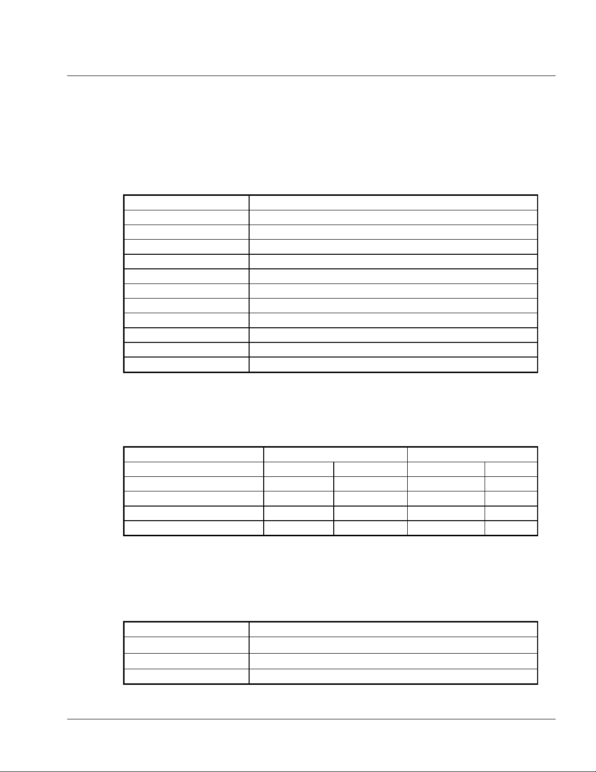
General Specifications for the DRB-25 are listed in Table 1-4.
Table 1-4 General Specifications
Specification Value
Power supply 110 / 240 V AC, 12 / 24 V DC
Analog performance TIA / EIA603
Digital performance TIA / IS102.CAAB
Frequency bands: VHF: 136 to 174 MHz
UHF (low): 400 to 470 MHz (future option)
Operating frequencies Selectable across full band
Dimensions: Width: 19 inches (483 mm)
Height: 14 inches (355 mm or 8 Rack Units)
Depth: 17.5 inches (445 mm)
Weight: Single radio: 58 lb (26 kg)
Dual radio: 81 lb (37 kg)
1.3.2 Power Consumption
Power Consumption for the configurations of the DRB-25 are listed in Table 1-5.
Table 1-5 Power Consumption
Configuration AC Consumption DC Consumption
Receive Transmit Receive Transmit
Single channel, 60 W 55 W 245 W 45 W 205 W
Single channel, 125 W 55 W 380 W 45 W 340 W
Additional channel, 60 W 26 W 210 W 20 W 180 W
Additional channel, 125 W 26 W 340 W 20 W 310 W
1.3.3 Environmental Specifications
The DRB-25 equipment is intended to be located in an indoor environment and meets the environmental
specifications detailed in Table 1-6.
Table 1-6 Environmental Specifications
Specification Value
Operating Temperature
Storage Temperature
Operating Altitude 0 to 5,000 m
°
C to +60°C
-30
º
C to +60ºC
-40
AMX–MA–00651 Issue 0.02 (USA)
8
Page 9

Installation and Operator Handbook Introduction
Specification Value
Relative humidity (noncondensing)
EMI/EMC Equivalent to FCC part 15, subpart A, C, and J
5% to 95% RH, non-condensing as defined in MIL-STD-810E Method
507.3 (humidity)
1.3.4 Applicable Standards
The DRB-25 is designed to meet the applicable requirements of recommendations and standards detailed in
Table 1-7.
Table 1-7 Applicable Standards
Function Standard
Digital mode performance TIA IS102.CAAB
Analog mode performance TIA 603
EMI/EMC NTIA Manual Chapter 5 FCC part 90
PSTN line isolation TS001 (Australia), AS3260 (Australia), FCC part 68 (USA)
AMX–MA–00651 Issue 0.02 (USA)
9
 Loading...