

Page 1

Installation and Operator Handbook Equipment Description
CONTENTS
2 EQUIPMENT DESCRIPTION
2.1 I
2.2 P
NTRODUCTION
OWER SOURCE OPTIONS
....................................................................................................................................................2
.....................................................................................................................................2
2.2.1 AC Power Supply ........................................................................................................................................2
2.2.2 DC Power Supply........................................................................................................................................2
2.2.3 AC Powered with DC Revert.......................................................................................................................3
2.2.4 Reference Oscillator Backup Power ...........................................................................................................3
2.3 P
LUG-IN MODULES
..............................................................................................................................................4
2.3.1 Transceiver Module.....................................................................................................................................4
2.3.2 Controller Module.......................................................................................................................................6
2.3.3 Power Amplifier Module.............................................................................................................................8
2.3.4 Power Supply Module .................................................................................................................................9
2.3.5 Interface Module .......................................................................................................................................11
LIST OF FIGURES
F
IGURE
F
IGURE
F
IGURE
F
IGURE
F
IGURE
F
IGURE
F
IGURE
2-1 P
OWER DISTRIB UTION OF AN
2-2 P
OWER DISTRIB UTION OF A
2-3 T
RANSCEIVER MODULE FRONT PANEL
2-4 C
ONTROLLER MODULE FRONT PANEL
2-5 P
OWER AMPLIFIER MODULE FRONT PANEL
2-6 P
2-7 I
OWER SUPPLY MODULE FRONT PANEL
NTERFACE MODULE FRONT PANEL
AC
DC P
POWERED
OWERED
DRB-25....................................................................................2
DRB-25......................................................................................3
..........................................................................................................5
...........................................................................................................7
...................................................................................................9
.....................................................................................................10
.............................................................................................................11
Page
2-1 T
RANSCEIVER MODULE CONTROLS AND INDICATORS
2-2 C
ONTROLLER MODULE CONTROLS AND INDICATORS
2-3 P
OWER SUPPLY MODULE CONTROLS AND INDICATORS
2-4 I
NTERFACE MODULE EXTERNAL INTERFACES
AMX–MA–00652 Issue 0.02 (USA)
1
LIST OF TABLES
................................................................................................6
.................................................................................................8
............................................................................................11
..........................................................................................................12
Page 2
Installation and Operator Handbook Equipment Description
2 EQUIPMENT DESCRIPTION
2.1 INTRODUCTION
DRB-25 equipment consists of modular hardware which is easily installed as a desktop cabinet, floor-mount
cabinet or into standard 19 inch racks.
The DRB-25 chassis and its component modules are described in the following paragraphs.
2.2 POWER SOURCE OPTIONS
2.2.1 AC Power Supply
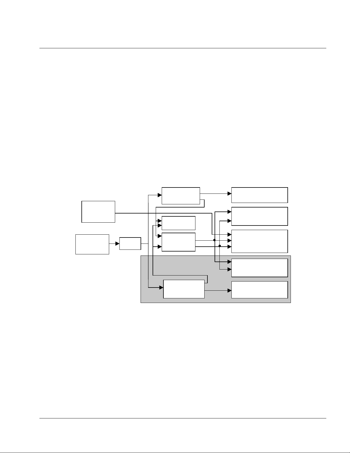
The DRB-25 may be powered from the 240 or 110 V AC power supply via one or two Power Supply
Modules. Figure 2-1 shows the power distribution of an AC powered DRB-25.
12V DC
Standby
110/240 V
AC Supply
Switch
Figure 2-1 Power Distribution of an AC powered DRB-25
2.2.2 DC Power Supply
The DRB-25 may be powered from 12 or 24 or 48 V DC power supplies via one or two DC/DC Power
Supply Modules. Alternatively, the DRB-25 may be powered directly from DC power sources as follows:
Power Supply
Module 1
Fans
System
PSU
Option for Second Channel
Power Supply
Module 2
7 V
12 V
Power Amplifier 1
Transceiver Module 1
Controller & Interface
Modules
Transceiver Module 2
Power Amplifier 2
• 12 V DC to 13.8 V DC (for 60 watt Power Amplifier Modules).
• 24 V DC to 28 V DC (for 125 watt Power Amplifier Modules).
Note that the RF output power of the DRB-25 is derated by 3 dB if the DC voltage is at the low end of the
range (i.e. at 12 or 24 V DC). When operating from a direct DC power source the Power Supply Modules are
replaced with blank panels.
AMX–MA–00652 Issue 0.02 (USA)
2
Page 3

Installation and Operator Handbook Equipment Description
Figure 2-2 shows the power distribution of a DC powered DRB-25.
12V DC
Standby
12/24V DC
Supply
Switch
Option for Second Channel
Figure 2-2 Power Distribution of a DC Powered DRB-25
2.2.3 AC Powered with DC Revert
The DRB-25 may be powered from the 240 or 110 V AC power supply via one or two Power Supply Modules
with provision for 12 or 24 V DC revert in the event that the AC power fails. The DC revert options are:
Optional DC/DC
Converter
Fans
System
PSU
Optional DC/DC
Converter
7 V
12 V
Power Amplifier 1
Transceiver Module 1
Controller & Interface
Modules
Transceiver Module 2
Power Amplifier 2
• 12 V DC to 13.8 V DC (for 60 watt Power Amplifier Modules).
• 24 V DC to 28 V DC (for 125 watt Power Amplifier Modules).
When using DC revert the RF output power of the DRB-25 is derated by 3dB if the DC voltage is at the low
end of the range (i.e. At 12 or 24 V DC). When operating from a direct DC power source the Power Supply
Modules are replaced with blank panels.
AC powered with 48 V DC revert is also available using external power supplies, however, where a 48 V DC
battery backed supply is available it is generally preferable to use this as the main power source for the DRB-
25.
2.2.4 Reference Oscillator Backup Power
The DRB-25 has provision for a user to connect a 12 V DC backup supply to keep the system reference
oscillator oven at its operating temperature in the event of a brief primary power failure. An interface module
connector acts as the connection point for the keep-alive power.
If the backup supply is not used, any interruption to the primary supply requires a start-up cycle of up to ten
minutes in which the reference oscillator heats up.
AMX–MA–00652 Issue 0.02 (USA)
3
Page 4

Installation and Operator Handbook Equipment Description
2.3 PLUG-IN MODULES
The DRB-25 has the following types of plug-in Modules:
• Transceiver Module.
• Controller Module.
• Power Amplifier Module.
• Interface Module.
• Power Supply Module.
2.3.1 Transceiver Module
The Transceiver Module (TM) provides full duplex radio operation for analog and digital modulation
schemes. Each module consists of an RF card for receive and transmit and a daughter board for digital signal
processing. Modules are standard half-Eurocard layout measuring 10.5 inches (6 Rack Units) high by 10
inches (250 mm) deep. The Transceiver Modules plug into a common backplane with the Controller Module,
providing seamless transfer and switching of traffic and control data.
Transceiver Modules are specific to frequency bands and are available for frequency bands; VHF (136 to 174
MHz), and UHF (low) (400 to 470 MHz). Each Transceiver module may be programmed with up to 512
channels.
Transceiver Modules of different bands are interchangeable provided the associated Power Amplifier is also
changed. The Transceiver Module is powered by 12 V and 7 V supplies from the System Power Supply
within the case of the DRB-25.
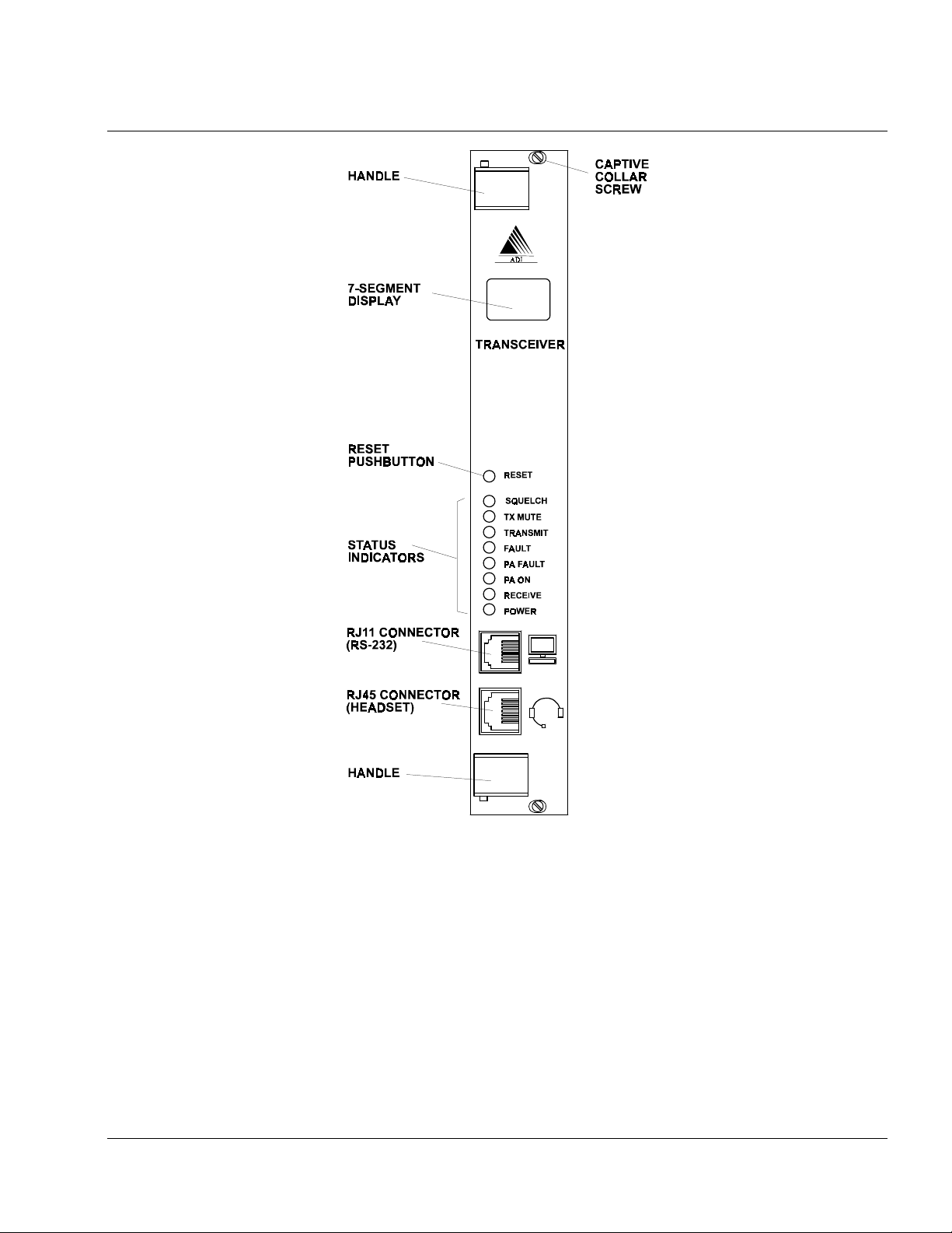
Two RJ style connectors are provided on the module front panel. The upper connector (RJ11) provides a
standard RS-232 serial interface which allows maintenance staff to program and configure the module using
the Transceiver Module Programmer application software from an external PC. The lower (RJ45) connector
provides an audio interface for the connection of a speaker, microphone or handset.
Internally to the DRB-25 the Transceiver Module provides two connections to its associated power amplifier;
the RF output and a serial data link for control and communication between the two modules. Figure 2-3
shows the front panel controls, indicators and connectors and Table 2-1 lists the control and indicator
functions.
AMX–MA–00652 Issue 0.02 (USA)
4
Page 5
Installation and Operator Handbook Equipment Description
The Transceiver Module also provides interfaces to the internal backplane for audio, data and control. The
Transceiver Module also provides an audio output interface for connection to a front panel speake when
configured as a single channel system with optional front panel speake module.
AMX–MA–00652 Issue 0.02 (USA)
Figure 2-3 Transceiver Module Front Panel
5
Page 6

Installation and Operator Handbook Equipment Description
Table 2-1 Transceiver Module Controls and Indicators
ITEM Description
7-segment display In normal operation indicates the current channel being used by the Transceiver
Module (in the range 0 to 511).
If an error condition is detected in either the Transceiver or PA Module then the
display indicates the relevant error code. An “E” is displayed with a number in
the range “1” to “99” displayed to indicate the error condition.
RESET Recessed pushbutton switch. Press to reset the Transceiver Module.
SQUELCH
(Green LED)
TX MUTE
(Green LED)
TRANSMIT
(Green LED)
FAULT
(Red LED)
PA FAULT
(Red LED)
PA ON
(Green LED)
RECEIVE
(Green LED)
POWER
(Green LED)
Illuminated when a signal has been received and the NAC or CxCSS has been
validated.
Illuminated when the selected channel has is “receive only” mode, i.e., it
receives signals and the operator can monitor the received signals, but nothing
can be transmitted.
Illuminated when the Transceiver Module is transmitting.
Illuminated when the self test and diagnostic routines have detected a fault
condition in the Transceiver Module circuitry. The 7-segment display indicates
the nature of the fault.
Illuminated when the self test and diagnostic routines have detected a fault
condition in the circuitry of the Power Amplifier Module used with this
Transceiver Module. The 7-segment display indicates the nature of the fault.
Illuminated when the Power Amplifier Module has received a transmit command
from the Transceiver Module and is transmitting.
Illuminated when a carrier has been detected on the receive frequency. If this
indicator is ON but the SQUELCH indicator is OFF then an invalid signal has
been received.
Illuminated when the Transceiver Module is receiving power from the power
supply.
2.3.2 Controller Module
The Controller Module (CM) provides central control functions for the DRB-25 and high-stability timing for
all radio elements. One Controller Module is required for each DRB-25 system. The module is a standard
half-Eurocar d plugged into a common backplane with the Transceiver M odules, providing seamless transfer
and switching of traffic and control data.
The Controller Module contains a 10 MHz oven-controlled reference oscillator from which all system timing
is derived. The Transceiver Modules are inhibited from transmitting if the reference clock fails. Since the
oven takes up to 10 minutes to reach its operating temperature and achieve the required stability provision is
made for the connection of an external oven supply (12 V DC) which can keep the oven at the required
temperature during power outages. It is also possible to supply an external 10 MHz reference directly to the
Controller Module which is then used instead of the internal reference oscillator.
The DRB-25 has six general-purpose inputs and outputs (provided on the Interface Module). These can be
programmed to be alarm inputs for functions such as site alarms, AC power failure alarms etc. The Controller
Module monitors all internal alarms generated by Transceiver Modules, Power Amplifier Modules and Power
Supply Modules. The Controller Module also monitors the general-purpose inputs and can be programmed to
activate a single general-purpose output or remotely interrogated to determine the cause of the alarm.
AMX–MA–00652 Issue 0.02 (USA)
6
Page 7
Installation and Operator Handbook Equipment Description
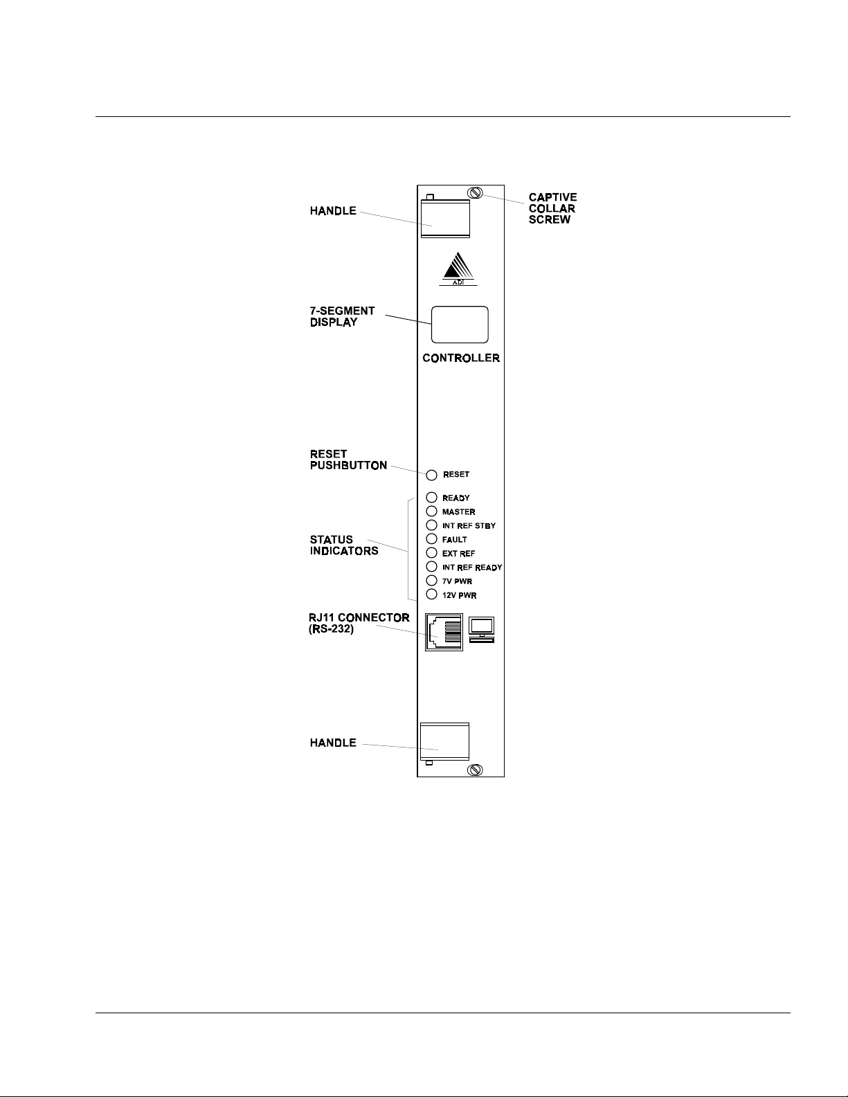
Figure 2-4 shows the front panel controls, indicators and connectors and Table 2-2 lists the control and
indicator functions.
There is a RESET switch, nine indicators and one RJ11 connector on the front panel of the Controller
Module. The RJ11 connector provides a standard RS 232 serial interface which allows maintenance
technicians to program and configure the module using the programmer and to monitor radio functions with a
computer.
AMX–MA–00652 Issue 0.02 (USA)
Figure 2-4 Controller Module Front Panel
7
Page 8

Installation and Operator Handbook Equipment Description
Table 2-2 Controller Module Controls and Indicators
Item Description
7-segment display An oscillating pattern indicates normal operation of the module.
If an error condition is detected in the Controller Module then the display indicates the
relevant error code.. A flashing “E” is displayed with number in the range “1” to “99”
is displayed to indicate the error condition.
RESET Recessed pushbutton switch. Press to reset the Controller Module.
READY
(Green LED)
MASTER
(Green LED)
INT REF STBY
(Green LED)
FAULT
(Red LED)
EXT REF
(Green LED)
INT REF READY
(Green LED)
7 V PWR
(Green LED)
12 V PWR
(Green LED)
Illuminated when the Controller Module is operating and ready for use.
Illuminated when the Controller Module is the master and is generating the 10 MHz
reference clock for the unit. This indicator is always ON, unless a redundant
controller is used in multi channel configurations.
Illuminated when the internal 10 MHz clock reference oscillator is operating from the
12 V DC STBY PWR on the Interface Module.
Illuminated when the self test and diagnostic routines have detected a fault condition
in the Controller Module circuitry. The 7-segment display indicates the nature of the
fault.
Illuminated when an external 10 MHz clock source is connected to the BNC
connector on the Interface Module.
Illuminated when the internal 10 MHz clock reference oscillator has reached
operating temperature.
Illuminated when the 7 volt supply is present in the Controller Module
Illuminated when the nominal 12 volt supply is present in the Controller Module.
2.3.3 Power Amplifier Module
The Power Amplifier Module (PAM) is a six Rack Units high plug-in module. One Power Amplifier Module
is required for each Transceiver Module. Power Amplifier Modules are specific to frequency bands and are
available for the same frequency bands as the Transceiver Modules.
Power Amplifier Modules are available in 60 W (VHF) and 125 W (VHF and UHF) versions. The 60 W
VHF version is for systems using analog FM and digital C4FM modulation schemes, and outputs up to 60 W
between 136 MHz and 160 MHz and up to 50 W between 160 MHz and 174 MHz. 125 W Power Amplifier
Modules support analog FM and digital C4FM. Each Power Amplifier Module has an on-board
Microcontroller which supervises its operation and reports alarms via a control link to the associated radios.
Power output is adjustable over a 10 dB range in increments of less than 1 dB. UHF Power Amplifier
Modules can be fitted with optional circulators.
Each Power Amplifier Module is powered by its associated Power Supply Module. The 60 W model operates
from a 12 V Power Supply Module while 125 W models operate from 24 V. All Power Amplifier Modules
for a given band are interchangeable provided that the Power Supply Module is changed if a 60 W Power
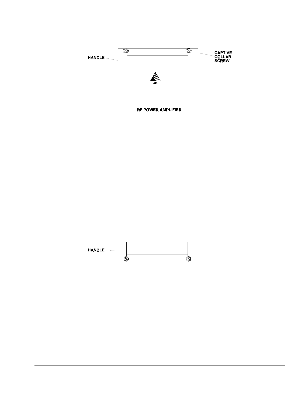
Amplifier Module is replaced by a 125 W Power Amplifier Module. Figure 2-5 shows the front panel layout.
AMX–MA–00652 Issue 0.02 (USA)
8
Page 9
Installation and Operator Handbook Equipment Description
Figure 2-5 Power Amplifier Module Front Panel
The Power Amplifier Module has two connectors. The N-type connector is the Power Amplifier output
connector, and the D connector contains RF input, DC power, and serial communications lines.
2.3.4 Power Supply Module
The Power Supply Module provides the system power supply and one Power Amplifier Module with DC
power derived from the 240 or 110 V AC power and is available in two versions depending on the Power
Amplifier Module being used:
• 240/110 V AC to 12 V DC for 60 W Power Amplifier Modules.
• 240/110 V AC to 24 V DC for 125 W Power Amplifier Modules.
AMX–MA–00652 Issue 0.02 (USA)
9
Page 10
Installation and Operator Handbook Equipment Description
The inputs of both 240/110 V power supplies are fuse-protected and the outputs are over-current protected.
They have dry contact (relay contacts) alarm outputs which close when the unit is operating correctly and
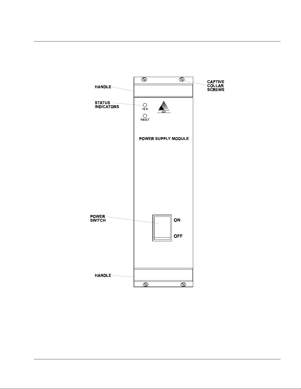
open in the event of a malfunction. Figure 2-6 shows the Power Supply Module front panel indicators and
Table 2-3 lists the indicator functions.
AMX–MA–00652 Issue 0.02 (USA)
Figure 2-6 Power Supply Module Front Panel
10
Page 11
Installation and Operator Handbook Equipment Description
Table 2-3 Power Supply Module Controls and Indicators
Item Description
ON/OFF Switch Controls application of AC supply to the Power Supply Module.
Red neon indicator
(part of switch)
12 V (or 24 V)
(Green LED)
FAULT (Red LED) Illuminated when there is a fault within the Power Supply Module
Illuminated when supply is present.
Illuminated when the DC supply is present.
2.3.5 Interface Module
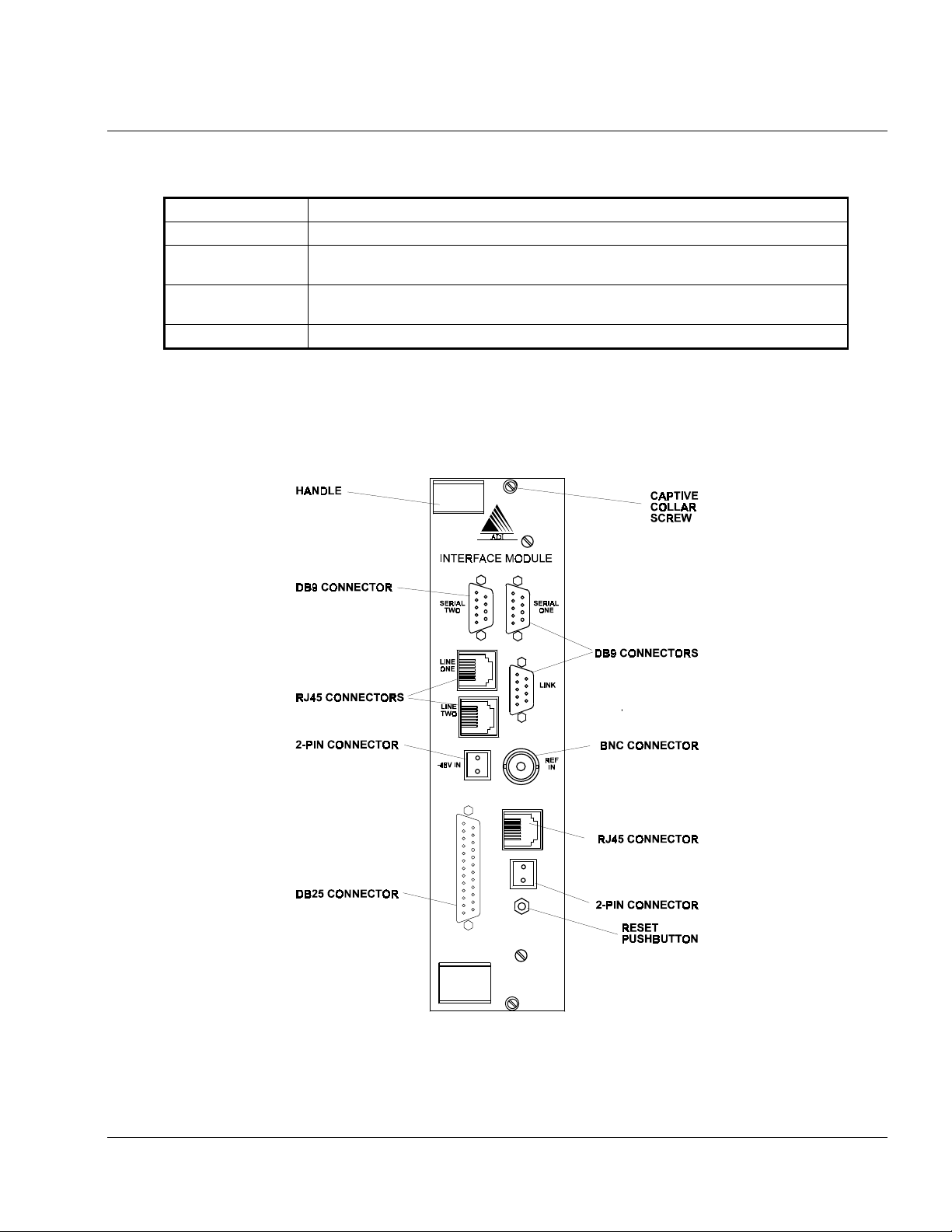
The Interface Module (IM) provides connections for the DRB-25 external interfaces. The Front Panel of the
Interface Module is shown in Figure 2-7 and the connector functions listed in Table 2-4. Connector pin-outs
are listed in section 3.6.5.
The 2-wire or 4-wire configuration of the Line 1 and Line 2 interfaces for telephone/microwave/tone remote
control connection is provided by an additional line interface daughterboard on the Interface Module.
AMX–MA–00652 Issue 0.02 (USA)
Figure 2-7 Interface Module Front Panel
11
Page 12

Installation and Operator Handbook Equipment Description
Daughterboards are available to provide this conne ction as 4 wire plus E & M; or 2 wire loop start and 2 wire
ground start. If no connection is required the daughterboard is not needed.
Table 2-4 Interface Module External Interfaces
Designation Connector Function
LINE 1 RJ45 Radio 1 connections for:
2 wire PSTN or PABX
4 wire + E & M microwave interconnect
2 or 4 wire tone remote unit
LINE 2 RJ45 Radio 2 connections for:
2 wire PSTN or PABX
4 wire + E & M microwave interconnect
2 or 4 wire tone remote unit
SERIAL 1 DB9 Socket Radio 1 data connection (RS-232)
SERIAL 2 DB9 Socket Radio 2 data connection (RS-232)
LINK DB9 Plug RS485 serial data connection for APCO Project 25 Fixed
Station Interface (Ef) , digital console interface or multi-site
voting (future options)
NET RJ45 Ethernet connection for network management interface (future
option)
I/O DB25 Socket General purpose input and output lines (6 inputs and 6
outputs), including dedicated outputs for antenna relay control
and dedicated inputs for transmit disable
REF IN BNC External 10 MHz reference oscillator input
STBY PWR 2-pin plug Standby power for reference oscillator oven.
-48 V IN 2-pin plug DC input for E & M signaling
The general-purpose digital I/O provides six configurable inputs and outputs. Two of the output lines may be configured by
jumper selection in the Interface Card to provide to drive 12 volt antenna relays for each of the transceivers. All other
outputs, and these two when not configured as antenna drivers, provide optically-isolated contact closures which can be
used to control other eq uipment.
The six inputs are also optically isolated. With an input of 5v to 10v they are sensed as active (on), when open circuited,
they are sensed as inactive (off). The first two inputs are used to disable the transmitter during test.
The general purpose input and output lines, apart from the antenna relay outputs and transmit disable inputs, are unused i n
the present software release. In future releases user-configurability will be available.
AMX–MA–00652 Issue 0.02 (USA)
12
 Loading...