

Westell Technologies 7500 Installation Manual

Method and Procedure
Field Operations Support MP-2009-12-004/ Issue 11/Date: 2/9/2011
Westell 7500 Wireless
Gateway Installation Guide
Process Owner: Centralized Operations - Field Operations Support
Unauthorized disclosure outside CenturyLink Corporation is prohibited
Information contained in this document is proprietary
1

Method and Procedure
Field Operations Support MP-2009-12-004/ Issue 11/Date: 2/9/2011
Table of Contents
1.0
TARGET AUDIENCE ....................................................................................................................................3
2.0
PURPOSE .....................................................................................................................................................3
3.0
GENERAL .....................................................................................................................................................3
4.0
EFFECTIVE DATE ........................................................................................................................................4
5.0
ASSOCIATED DOCUMENTS.......................................................................................................................4
6.0
EQUIPMENT .................................................................................................................................................4
7.0
WESTELL 7500 WIRELESS GATEWAY GENERAL INFORMATION........................................................5
8.0
INSTALLATION GUIDE ................................................................................................................................8
9.0
USER INTERFACE .......................................................................................................................................9
10.0 DSL GATEWAY CONFIGURATION - DHCP, STATIC, WIRELESS CONNECTION & BRIDGE MODE 9
11.0 CONTACTS.................................................................................................................................................31
12.0 AUTHORIZATION .......................................................................................................................................31
Process Owner: Centralized Operations - Field Operations Support
Unauthorized disclosure outside CenturyLink Corporation is prohibited
Information contained in this document is proprietary
2
Method and Procedure
Field Operations Support MP-2009-12-004/ Issue 11/Date: 2/9/2011
1.0 TARGET AUDIENCE
1.1 Functional workgroup(s) impacted by this Method and Procedure:
Workgroup
Residential & Business
CenturyLink H.S.I.
Technicians
2.0 PURPOSE
2.1 Subject:
Installation instructions for the Westell 7500 Wireless Gateway
2.2 Background:
• The Westell 7500 became the standard wireless gateway for all CenturyLink technicians
around mid to late October 2010.
o The firmware for this device was changed. The new firmware is 5.02.00.04. The
model is A90-750022-07.
• For Legacy CenturyTel, the Westell 7500 (version 14) wireless DSL gateway replaced the Westell
327W series DSL gateways for residential and business customers effective October 2009. Once
version 14 is depleted, the new version will be distributed.
• The existing wireless adapter offered by CenturyLink can be used with this gateway.
2.3 Revisions:
Issue Section Paragraph
6 All Updated to include standardization of this device for all CenturyLink
technicians. This device will now be used by all techs and replaces
the Zyxel 660HW for Legacy EQ. This device will also be used for
FTTP/FTTC-E and replace the Zyxel P330 router for Legacy EQ.
7 6.0 Removed material codes. All material codes are located on the HSI
Supply List.
8 10.0 Added additional note about the VPI/VCI auto-detecting the correct
configuration.
9 Added clarifying statements on the configurations.
10 10.1 Corrected the DHCP Server Pool size
11
2.2,
10.4
Removed reference to the Westell 7500 becoming the standard
FTTx device.
11 6.0 Updated the adapter from the G202 to the N220. This changed on
1/17/2011.
11 10.4 Updated the Static IP configuration information for a single static IP.
Separated out the steps/screen shots for Leg EQ vs Leg
CenturyTel.
Process Owner: Centralized Operations - Field Operations Support
Unauthorized disclosure outside CenturyLink Corporation is prohibited
Information contained in this document is proprietary
Revision Summary
3
Method and Procedure
Field Operations Support MP-2009-12-004/ Issue 11/Date: 2/9/2011
3.0 GENERAL
3.1 Roles and Responsibilities:
The following table lists workgroup(s) responsible for implementing the Method and Procedure.
Workgroup Job Function Performed
H.S.I. Technicians Installation of the Westell 7500 Wireless Gateway
3.2 Compliance:
This practice is mandatory as written.
3.3 Adopted for Use:
This practice has been adopted for use in the following business units/divisions of CenturyLink.
(a) Full (Home) Install Technicians
4.0 EFFECTIVE DATE
Effective Date Expiration Date
October 2009 for Legacy CenturyTel & October
2010 for all CenturyLink technicians
5.0 ASSOCIATED DOCUMENTS
HSI Supply List
Installation Guide that customers
should receive on self installs,
home installs, or tech deliveries
HSI CPE REPAIR/REPLACEMENT &
RETURN POLICY
http://nsl.corp.intranet/ADSL/HSI_SUPPLY_LIST.pdf
Install Guide Oct
2010.pdf
http://nsl/ncs_jobaid/2010/ja_2010_05_001.pdf
Until Further Notice
Ordering H.S.I. and PRISM
Equipment in CART (Create a
Requisition Today)
Identifying when a Splittered
Installation is Required
Splitter Installations
Wireless USB Adapter
HSI Full Installation Guide
Process Owner: Centralized Operations - Field Operations Support
Unauthorized disclosure outside CenturyLink Corporation is prohibited
http://nsl/ncs_jobaid/2010/ja_2010_02_008.pdf
http://nsl/ncs_jobaid/2010/ja_2010_02_001.pdf
http://nsl.corp.intranet/ncs_jobaid/2010/ja_2010_06_004.pdf
http://nsl/ncs_jobaid/2010/ja_2010_03_004.pdf
http://nsl.corp.intranet/ncs_practices/2006/mp_2006_09_003.pdf
Information contained in this document is proprietary
4
Method and Procedure
Field Operations Support MP-2009-12-004/ Issue 11/Date: 2/9/2011
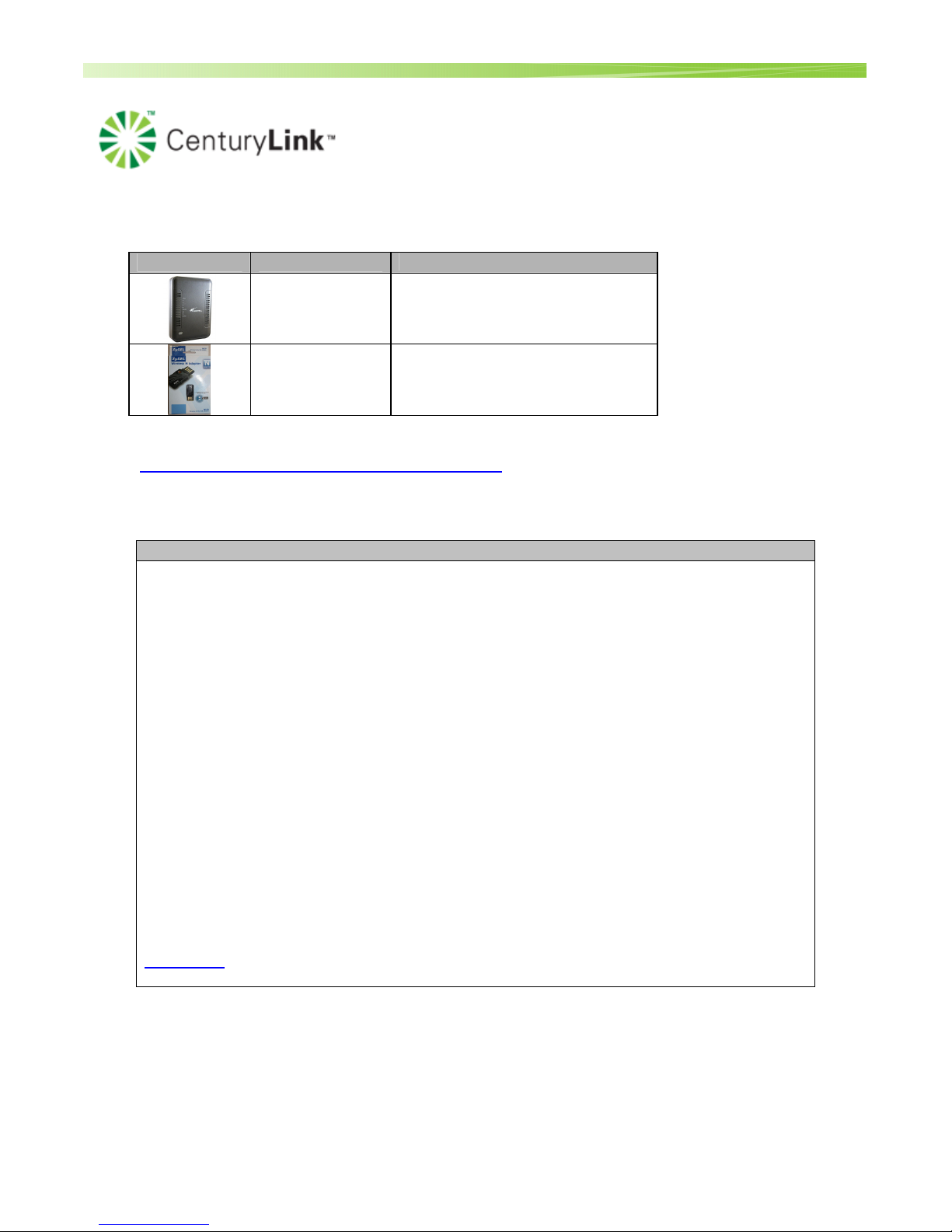
6.0 Equipment
Wireless CPE CPE Description
Westell 7500
Wireless DSL
Gateway
Zyxel N220
Wireless USB
Adapter
Legacy EQ S&E Codes
• BHSZYXS(xxx) for
splittered
• BHSZYXF(xxx) for filtered
BHS2WRS (USB)
Material codes can be found on the HSI Supply List:
http://nsl.corp.intranet/ADSL/HSI_SUPPLY_LIST.pdf
7.0 Westell 7500 WIRELESS GATEWAY GENERAL INFORMATION
General Information
Minimum Requirements
•
Pentium II processor or better with Windows XP or newer
•
64 MB RAM (128 recommended)
•
25 MB free hard drive space
•
Network Interface Card (NIC/Ethernet) or available USB port
Gateway Features
Multi-port ADSL2/ 2+ Router:
• PPPoE and DHCP WAN Protocols
• VersaPort provides Ethernet WAN interface for FTTx (Fiber to the Premise, or Fiber to the
Curb-Ethernet)
• Built-in ADSL2/ 2+ Modem
• NAT router for multiple computers
• 4-port switch for LAN
• Built-in 802.11b/g wireless access point for mobile LAN
• Can be managed locally or remotely
• Advanced Custom Firewall
Manufacturer Documentation Links
Data Sheet
Process Owner: Centralized Operations - Field Operations Support
Unauthorized disclosure outside CenturyLink Corporation is prohibited
Information contained in this document is proprietary
5
Method and Procedure
Field Operations Support MP-2009-12-004/ Issue 11/Date: 2/9/2011
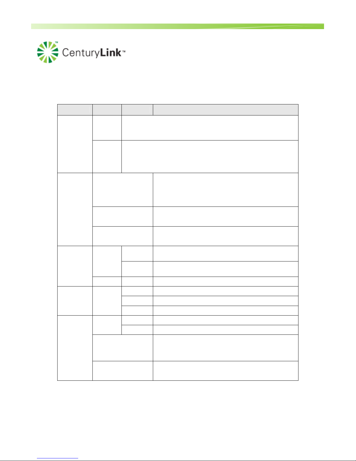
Front Panel
LED COLOR STATUS DESCRIPTION
On
Green
Router power is ON.
POWER
On
POST (Power On Self Test), Failure (not bootable) or Device
Red
Malfunction. Note: The Power LED should be red no longer than two
seconds after the power on self test passes.
Powered device is connected to the associated port
(includes devices with wake-on LAN capability where
slight voltage is supplied to an Ethernet connection).
Note: When using the optional uplink port (E1), Ethernet
LAN connection is limited to E2, E3, and E4.
10/100 Base-T LAN activity is present (traffic in either
direction)
ETHERNET
1 - 4
Solid Green
Flashing Green
Router power is OFF, no cable or no powered device is
Wireless
Green
DSL Green
Green
Off
On
Blinking
Off
On
Blinking
Off
On
Blinking
connected to the associated port.
The Westell Device is ready, but is not sending/receiving
data through the wireless LAN.
The Westell Device is sending/receiving data through the
wireless LAN.
The wireless LAN is not ready or has failed.
The DSL line is up.
The Westell Device is initializing the DSL line.
The DSL line is down.
The Internet connection is up.
The Westell Device is sending/receiving data.
Device attempted to become IP connected and failed (no
INTERNET
Red
DHCP response, no PPP response, PPP authentication
failed, no IP Address from IPCP, etc.).
Router power is OFF, Router is in Bridge Mode, or the
Off
ADSL connection is not present.
Process Owner: Centralized Operations - Field Operations Support
Unauthorized disclosure outside CenturyLink Corporation is prohibited
Information contained in this document is proprietary
6
Method and Procedure
Field Operations Support MP-2009-12-004/ Issue 11/Date: 2/9/2011
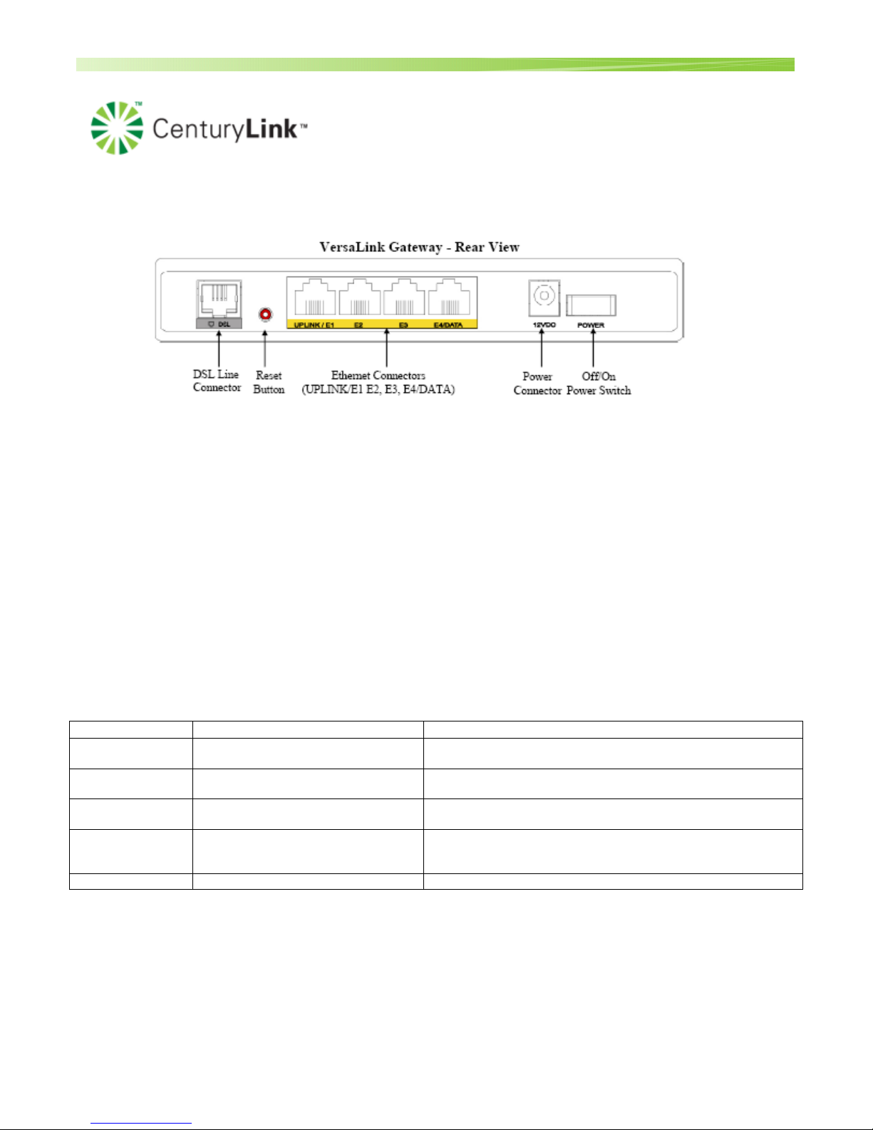
Rear Panel
DSL Line Connector (RJ-11)
Reset push button
Four Ethernet (RJ-45) connectors with optional UPLINK/E1 port and optional E4/DATA port.
There is no USB port on the 7500. However, customers can use a Wireless USB adapter. It plugs into
the PC and then the customer can connect wirelessly to the 7500.
NOTE:
When using the optional UPLINK/E1 jack (when VersaLink is configured for WAN Uplink mode), Ethernet LAN
connections are limited to ports E2, E3, and E4. The Uplink feature is optional. If Uplink is not enabled via the
Web pages, VersaLink will use DSL as the WAN interface.
Power connector (12 VDC) barrel
Off/On power switch
Connector Descriptions – The following chart explains the device’s rear panel connector types.
Name Type Function
DSL LINE Modular 6-pin (RJ-11) DSL jack
UPLINK/E1 Modular 8-pin (RJ-45) Ethernet jack
E2 – E3 Modular 8-pin (RJ-45) Ethernet jack
E4/DATA Modular 8-pin (RJ-45)Ethernet jack
POWER Barrel Connector Connects the 12VDC power connector to an AC wall jack.
Connects the Router to a telephone jack that has active ADSL
service or to the DSL port of a POTS splitter.
Connects the Router to a PC or Hub via 10/100 BaseT
Ethernet.
Connects the Router to a PC or Hub via 10/100 BaseT
Ethernet.
When the Ethernet connector is plugged in to the Router’s
DATA port, the USB cable can then be plugged in to the USB
port on a PC or Hub.
Process Owner: Centralized Operations - Field Operations Support
Unauthorized disclosure outside CenturyLink Corporation is prohibited
Information contained in this document is proprietary
7
Method and Procedure
Field Operations Support MP-2009-12-004/ Issue 11/Date: 2/9/2011
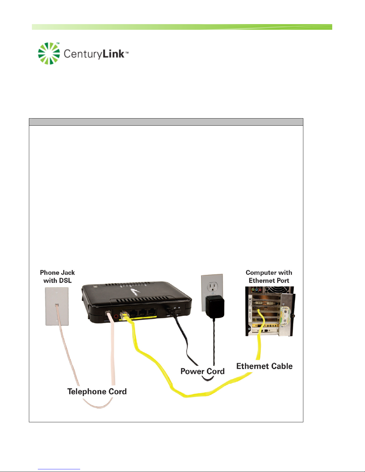
8.0 INSTALLATION GUIDE
Action
Install Gateway
NOTE: The Westell 7500 is pre-configured to automatically auto detect the
connection parameters (DHCP, PPPoE , VPI, VCI).
With the launch of version 22, the gateway includes an automated installation process known
as Home Device Manager (HDM). HDM automatically configures the gateway, walks the
customer through creation of their CenturyLink username/password, installs CenturyLink
Help (for residential customers) and takes the customer to the CenturyLink portal.
Technicians must complete the Home Device Manager (HDM) set-up procedure during gateway
installation (or replacement). Refer to the Associated Documents section of this document for the Full
Installation Guide M&P.
1. Turn your computer on.
2. Start browser (Internet Explorer)
• The gateway will automatically attempt to connect via DHCP or PPPoE. If successful
the HDM (Home Device Manager) flow will start. The auto detection will take
around 1-2 minutes.
Process Owner: Centralized Operations - Field Operations Support
Unauthorized disclosure outside CenturyLink Corporation is prohibited
Information contained in this document is proprietary
8

Method and Procedure
Field Operations Support MP-2009-12-004/ Issue 11/Date: 2/9/2011
There’s also a You Tube video available for customers on self installations that demonstrates
how to install the gateway. http://www.youtube.com/watch?v=yvbWApqFIo0
A separate video is available for how to activate CenturyLink H.S.I. :
http://www.youtube.com/watch?v=5y5ux70i4o4
Note: In the event a tech is on a trouble and HDM gets locked up, the tech can release HDM and bypass the installation flow. Refer to the H.S.I. Full Installation Guide M&P under Associated
Documents within this document for instructions on this.
9.0 USER INTERFACE
Westell gateways are configured via a web-based Graphical User Interface (GUI). To connect to the user
interface:
1. Open up a browser (Internet Explorer)
2. Type in 10.0.0.1 and hit Enter
3. If there isn’t a connection already configured, you will be launched to the Connection screen.
……………………………………………………………………………………………………………
The following sections are provided as a reference in the event a technician needs to validate
the configuration.
10.0 DSL GATEWAY CONFIGURATION – PPPoE, DHCP, STATIC/MULTIPLE STATIC & BRIDGE MODE
10.1 DEFAULT SETTINGS
(Note: Although the default for the VPI/VCI is 8/35, the device will be able to auto-detect if it should be 8/35
or not. In the case of Madison River Properties, it will switch over to 0/35 after attempting the 8/35. This
will take about 1-2 minutes. )
WAN (ADSL):
Encapsulation: ENET Encap
Multiplexing: LLC
VPI: 8
VCI: 35
IP Address: Obtained automatically
Process Owner: Centralized Operations - Field Operations Support
Unauthorized disclosure outside CenturyLink Corporation is prohibited
Information contained in this document is proprietary
9

Method and Procedure
Field Operations Support MP-2009-12-004/ Issue 11/Date: 2/9/2011
LAN:
IP Address: 10.0.0.1
DHCP Server Starting Address: 10.0.0.2
DHCP Server Pool Size: 32
WLAN: Enabled by default
SSID: Westell#### (#### represents the last 4 of the serial number)
Channel: 6
Security: WPA
Key: Pre-generated listed on the label.
Process Owner: Centralized Operations - Field Operations Support
Unauthorized disclosure outside CenturyLink Corporation is prohibited
Information contained in this document is proprietary
10
Method and Procedure
Field Operations Support MP-2009-12-004/ Issue 11/Date: 2/9/2011
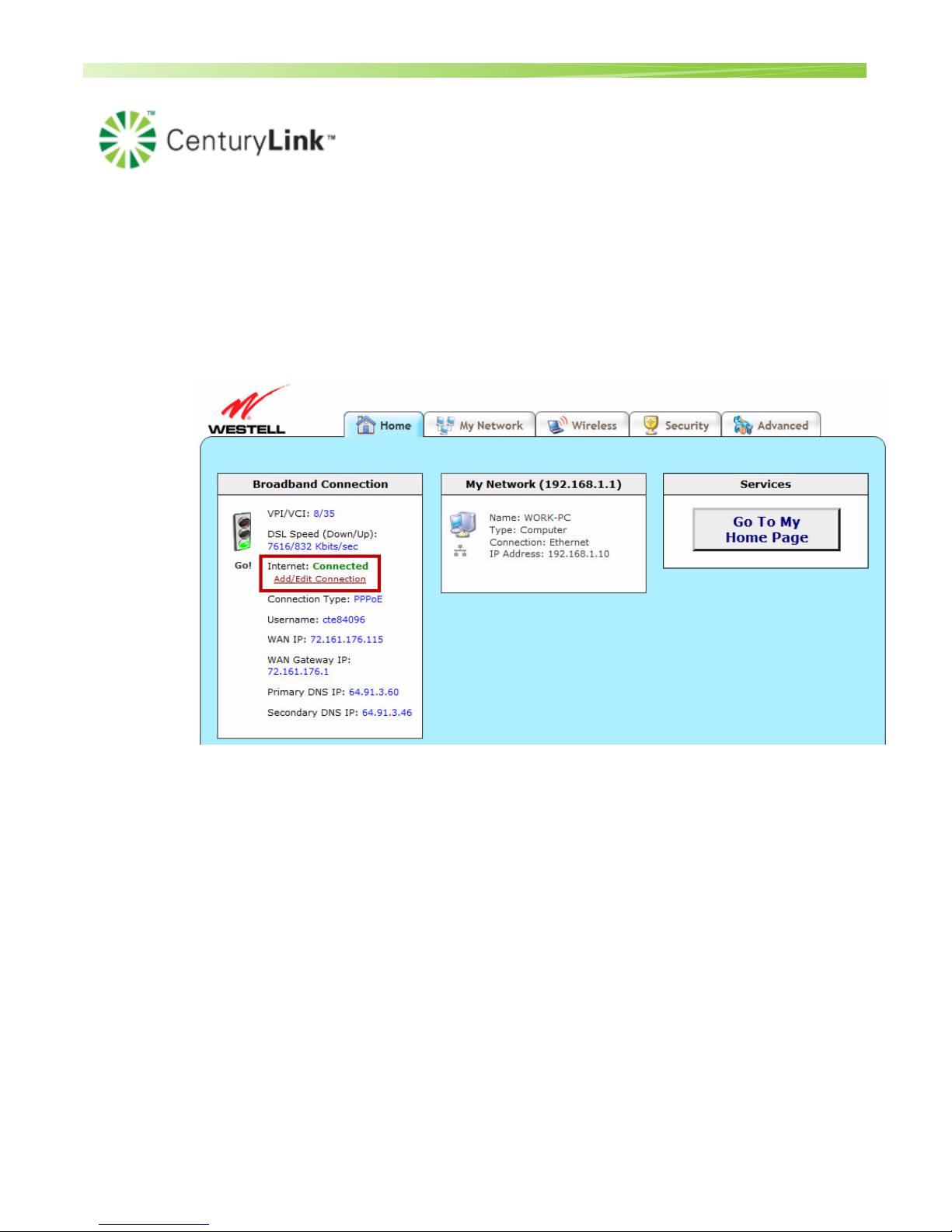
10.2 Configuring to the 7500 gateway for a PPPoE customer
IF HDM recognizes that the account is PPPoE, the PPPoE Account ID and password will already be built in as a
generic connection by default.
If there is already an account in the device, they will see the information under the Broadband Connection screen.
• If you need to modify the account information, click “Add/Edit Connection”.
Process Owner: Centralized Operations - Field Operations Support
Unauthorized disclosure outside CenturyLink Corporation is prohibited
Information contained in this document is proprietary
11
 Loading...