


DUAL CONNECT NAT ROUTER (MODEL 2200)
WITH DMHTM TECHNOLOGY
USER GUIDE
© Copyright 2003 Westell, Inc. |
i |
030-300372 Rev. A |
|
|
July 2003 |

User Guide |
Westell Dual Connect NAT Router with DMH Technology |
TABLE OF CONTENTS
1. |
PRODUCT DESCRIPTION .................................................................................................................................. |
|
1 |
|
2. |
SAFETY INSTRUCTIONS ................................................................................................................................... |
|
1 |
|
3. |
REGULATORY INFORMATION ........................................................................................................................ |
|
2 |
|
|
3.1 |
FCC Compliance Note............................................................................................................................... |
|
2 |
|
3.2 |
Canada Certification Notice....................................................................................................................... |
|
3 |
4. |
SYSTEM REQUIREMENTS................................................................................................................................. |
|
4 |
|
|
4.1 |
Minimum System Requirements for 10/100 Base-T/Ethernet Installation |
................................................4 |
|
|
4.2 |
Minimum System Requirements for USB Installation .............................................................................. |
4 |
|
5. |
INSTALLING THE HARDWARE........................................................................................................................ |
|
5 |
|
|
5.1 |
Installation Requirements .......................................................................................................................... |
|
5 |
|
5.2 |
Before you begin: ...................................................................................................................................... |
|
5 |
|
5.3 |
Microfilters ................................................................................................................................................ |
|
5 |
|
5.4 |
Router Installations.................................................................................................................................... |
|
5 |
|
5.5 |
LED Indicators........................................................................................................................................... |
|
8 |
|
5.6 |
Cable Connectors and Switch Locations ................................................................................................... |
|
8 |
6. |
INSTALLING THE USB DRIVERS................................................................................................................... |
|
10 |
|
|
6.1 |
CD-ROM Installation: ............................................................................................................................. |
|
10 |
|
6.2 |
Installing the USB Drivers for Windows 98............................................................................................ |
|
10 |
|
6.3 |
Installing the USB Drivers for Windows ME.......................................................................................... |
|
16 |
|
6.4 |
Installing the USB Driver for Windows 2000 |
......................................................................................... |
18 |
|
6.5 |
Installing the USB Driver for Windows XP ............................................................................................ |
|
21 |
7. |
CONFIGURING THE ROUTER FOR INTERNET CONNECTION ................................................................. |
23 |
||
|
7.1 |
Setting Up an Account Profile ................................................................................................................. |
|
23 |
|
7.2 |
Establishing a PPP Session ...................................................................................................................... |
|
27 |
|
7.3 |
Disconnecting a PPP Session................................................................................................................... |
|
29 |
|
7.4 |
Service Configuration.............................................................................................................................. |
|
31 |
|
7.5 |
Exiting the Dual Connect NAT Router.................................................................................................... |
|
34 |
8. |
SETTING UP MACINTOSH OS X..................................................................................................................... |
|
35 |
|
9. |
HOME |
.................................................................................................................................................................. |
|
39 |
|
9.1 |
Setting Up Advanced Configuration........................................................................................................ |
|
39 |
|
9.2 |
Adding Account Profiles ......................................................................................................................... |
|
40 |
|
|
|
||
030-300372 Rev. A |
ii |
July 2003 |
||

User Guide |
Westell Dual Connect NAT Router with DMH Technology |
||
10. STATUS............................................................................................................................................................... |
|
42 |
|
10.1 |
Connection Summary .............................................................................................................................. |
|
42 |
10.2 |
About ....................................................................................................................................................... |
|
43 |
11. CONFIGURATION ............................................................................................................................................. |
|
44 |
|
11.1 |
VC Configuration .................................................................................................................................... |
|
44 |
Configuring the Router’s Protocol Settings.......................................................................................................... |
|
48 |
|
11.2 |
DNS Configuration.................................................................................................................................. |
|
52 |
11.3 |
DHCP Configuration (Private LAN) ....................................................................................................... |
|
54 |
11.4 |
Private LAN Configuration ..................................................................................................................... |
|
58 |
11.5 |
Public LAN Configuration....................................................................................................................... |
|
59 |
11.6 |
Single Static IP Configuration ................................................................................................................. |
|
64 |
11.7 |
Service Configuration.............................................................................................................................. |
|
70 |
11.8 |
Firewall Configuration............................................................................................................................. |
|
78 |
11.9 |
ATM Loopbacks...................................................................................................................................... |
|
81 |
12. SETTING UP ADVANCED SERVICE CONFIGURATION |
.............................................................................82 |
||
12.1 |
Port Forwarding Ranges of Ports............................................................................................................. |
|
83 |
12.2 |
Adding Port Forwarding Ports................................................................................................................. |
|
83 |
12.3 |
Port Forwarding Trigger Ports................................................................................................................. |
|
84 |
12.4 |
Adding Local Trigger Ports ..................................................................................................................... |
|
85 |
12.5 |
Static NAT............................................................................................................................................... |
|
86 |
12.6 |
Enabling Static NAT................................................................................................................................ |
|
86 |
12.7 |
Disabling Static NAT............................................................................................................................... |
|
87 |
13. MAINTENANCE................................................................................................................................................. |
|
89 |
|
13.1 |
Backup/Store............................................................................................................................................ |
|
89 |
13.2 |
Firewall Log ............................................................................................................................................ |
|
90 |
13.3 |
Change Password..................................................................................................................................... |
|
91 |
13.4 |
Remote Access......................................................................................................................................... |
|
92 |
13.5 |
Update Device ......................................................................................................................................... |
|
93 |
14. TROUBLESHOOTING ....................................................................................................................................... |
|
98 |
|
14.1 |
System Self Tests..................................................................................................................................... |
|
98 |
14.2 |
Diagnostic Logs..................................................................................................................................... |
|
100 |
14.3 |
WAN VC Statistics................................................................................................................................ |
|
102 |
14.4 |
Ethernet Statistics .................................................................................................................................. |
|
103 |
14.5 |
Transceiver Statistics ............................................................................................................................. |
|
104 |
14.6 |
USB Port Statistics ................................................................................................................................ |
|
105 |
030-300372 Rev. A |
iii |
July 2003 |
|

User Guide |
Westell Dual Connect NAT Router with DMH Technology |
|
|
14.7 LAN Statistics........................................................................................................................................ |
106 |
15. |
HELP.................................................................................................................................................................. |
107 |
16. |
NAT SERVICES................................................................................................................................................ |
119 |
17. |
TECHNICAL SUPPORT INFORMATION ...................................................................................................... |
123 |
18. |
WARRANTY INFORMATION ........................................................................................................................ |
123 |
19. |
PRODUCT SPECIFICATIONS......................................................................................................................... |
124 |
20. |
SOFTWARE LICENSE AGREEMENT............................................................................................................ |
125 |
21. |
PUBLICATION INFORMATION..................................................................................................................... |
126 |
030-300372 Rev. A |
iv |
July 2003 |
User Guide |
Westell Dual Connect NAT Router with DMH Technology |
1. PRODUCT DESCRIPTION
The Westell® Dual Connect NAT Router with DMHTM technology adds reliable, high-speed, Internet access to your existing home or office phone line. Your ADSL connection is “always-on” ending the hassles of dial-up modems and busy signals. Installation is easy ... no tools ... no headaches. Simply connect the hardware, apply power, and perform the simple software configuration for your Dual Connect NAT Router.
This Router is capable of data rates hundreds of times faster than a traditional analog modem. But unlike analog modems, Westell’s Dual Connect NAT Router allows you to use the same phone line for simultaneous voice/fax communications and high-speed Internet access, eliminating the need for dedicated phone lines for voice and data needs. The Plug and Play feature means that no user configuration is required.
Your Westell modem is equipped with the latest in DSL modem technology. One of the innovative features included within your modem is a technology called Dynamic Multi-Hybrid or DMHTM. This technology enables your modem to achieve the fastest possible connection under various loop (telephone wires) conditions.
NOTE: Hereafter the Westell Dual Connect NAT Router will be referred to as “Dual Connect NAT Router” or “Router.”
2. SAFETY INSTRUCTIONS
Never install any telephone wiring during a lightning storm.
Never install telephone jacks in wet locations unless the jack is specifically designed for wet locations.
Never touch non-insulated telephone wires or terminals unless the telephone line has been disconnected at the network interface.
Use caution when installing or modifying telephone lines.
 WARNING
Risk of electric shock. Voltages up to 140 Vdc (with reference to ground) may be present on telecommunications circuits.
030-300372 Rev. A |
1 |
July 2003 |

User Guide |
Westell Dual Connect NAT Router with DMH Technology |
3. REGULATORY INFORMATION
3.1 FCC Compliance Note
This equipment has been tested and found to comply with the limits for a Class B digital device, pursuant to Part 15 of the Federal Communication Commission (FCC) Rules. These limits are designed to provide reasonable protection against harmful interference in a residential installation. This equipment generates, uses, and can radiate radio frequency energy, and if not installed and used in accordance with the instructions, may cause harmful interference to radio communications. However, there is no guarantee that interference will not occur in a particular installation. If this equipment does cause harmful interference to radio or television reception, which can be determined by turning the equipment OFF and ON, the user is encouraged to try to correct the interference by one or more of the following measures:
•Reorient or relocate the receiving antenna.
•Increase the separation between the equipment and the receiver.
•Connect the equipment to a different circuit from that to which the receiver is connected.
•Consult the dealer or an experienced radio/TV technician for help.
PART 68 - COMPLIANCE REGISTRATION
This equipment (Model 2200) complies with Part 68 of the FCC rules and the requirements adopted by the ACTA. A label on the bottom of this equipment contains, among other information, the Ringer Equivalence Number (REN), and the product identifier. For products approved after July 23, 2001 the product identifier is in the format US:AAAEQ##TXXXX. The digits represented by ## are the REN without a decimal point (e.g. 03 is a REN of 0.3). The REN is used to determine the number of devices that may be connected to a telephone line. For earlier products, the REN is separately shown on the label. If requested, this number must be provided to the telephone company.
Excessive RENs on a telephone line may result in the devices not ringing in response to an incoming call. In most, but no all areas, the sum of RENs should not exceed five (5.0). To be certain of the number of devices that may be connected to a line, as determined by the total RENs, contact the local telephone company.
This equipment is designated to connect to the telephone network or premises wiring using a compatible modular jack that is Part 68 compliant. An FCC compliant telephone cord and modular plug is provided with the equipment. See the Installation Information section of this User Guide for details.
A plug and jack used to connect this equipment to the premises wiring and telephone network must comply with the applicable FCC Part 68 rules and requirements adopted by the ACTA. A compliant telephone cord and modular plug is provided with this product. It is designed to be connected to a compatible modular jack that is also compliant. See installation instruction for details.
If this terminal equipment (Model 2200) causes harm to the telephone network, the telephone company may request you to disconnect the equipment until the problem is resolved. The telephone company will notify you in advance if temporary discontinuance of service is required. If advance notification is not practical, the telephone company will notify you as soon as possible. You will be advised of your right to file a complaint with the FCC if you believe such action is necessary.
If you experience trouble with this equipment (Model 2200), do not try to repair the equipment yourself. The equipment cannot be repaired in the field. Contact Westell for instructions on product return.
030-300372 Rev. A |
2 |
July 2003 |

User Guide |
Westell Dual Connect NAT Router with DMH Technology |
The telephone company may make changes to their facilities, equipment, operations, or procedures that could affect the operation of this equipment. If this happens, the telephone company will provide advance notice in order for you to make the modifications necessary to maintain uninterrupted service.
If your home has specially wired alarm equipment connected to the telephone line, ensure that the installation of this equipment (Model 2200) does not disable your alarm equipment. If you have questions about what will disable alarm equipment, consult your telephone company or a qualified installer.
This equipment cannot be used on public coin phone service provided by the telephone company. Connection of this equipment to party line service is subject to state tariffs.
3.2 Canada Certification Notice
The Industry Canada label identifies certified equipment. This certification means that the equipment meets certain telecommunications network protective, operations and safety requirements as prescribed in the appropriate Terminal Equipment Technical Requirements document(s). The department does not guarantee the equipment will operate to the user’s satisfaction.
This equipment meets the applicable Industry Canada Terminal Equipment Technical Specification. This is confirmed by the registration number. The abbreviation, IC, before the registration number signifies that registration was performed based on a Declaration of Conformity indicating that Industry Canada technical specification were met. It does not imply that Industry Canada approved the equipment. The Ringer Equivalence Number (REN) is 0.0. The Ringer Equivalence Number that is assigned to each piece of terminal equipment provides an indication of the maximum number of terminals allowed to be connected to a telephone interface. The termination on an interface may consist of any combination of devices subject only to the requirement that the sum of the Ringer Equivalence Numbers of all the devices does not exceed five.
Before installing this equipment, users should ensure that it is permissible to be connected to the facilities of the local Telecommunication Company. The equipment must also be installed using an acceptable method of connection. The customer should be aware that compliance with the above conditions may not prevent degradation of service in some situations. Connection to a party line service is subject to state tariffs. Contact the state public utility commission, public service commission, or corporation commission for information.
If your home has specially wired alarm equipment connected to the telephone line, ensure that the installation of this equipment (Model 2200) does not disable your alarm equipment. If you have questions about what will disable alarm equipment, consult your telephone company or a qualified installer.
If you experience trouble with this equipment (Model 2200), do not try to repair the equipment yourself. The equipment cannot be repaired in the field and must be returned to the manufacturer. Repairs to certified equipment should be coordinated by a representative, and designated by the supplier. Refer to section 12 in this User Guide for further details.
The termination on an interface may consist of any combination of devices subject only to the requirement that the sum of the Ringer Equivalence Numbers of all the devices does not exceed five.
Users should ensure, for their own protection, that the electrical ground connections of the power utility, telephone lines, and internal, metallic water pipe system, if present, are connected together. This precaution may be particularly important in rural areas.
 CAUTION
Users should not attempt to make such connections themselves, but should contact the appropriate electrical inspection authority, or electrician, as appropriate.
030-300372 Rev. A |
3 |
July 2003 |

User Guide |
Westell Dual Connect NAT Router with DMH Technology |
4. SYSTEM REQUIREMENTS
4.1 Minimum System Requirements for 10/100 Base-T/Ethernet Installation
The following system specifications are required for optimum performance of the Dual Connect NAT Router via 10/100 Base-T installation:
•Pentium® or equivalent and above class machines, Macintosh
•Microsoft® Windows® (98, 2000, ME, NT 4.0, or XP) or Macintosh® OS X installed
•Computer Operating System CD-ROM on hand
•Internet Explorer 4.x or Netscape Navigator 4.x or higher
•64 MB RAM (128 MB recommended)
•10 MB of free hard drive space
•TCP/IP Protocol stack installed
•10/100 Base-T Network Interface Card (NIC)
4.2Minimum System Requirements for USB Installation
The following system specifications are required for optimum performance of the Dual Connect NAT Router via USB installation:
•Pentium® or equivalent and above class machines
•Microsoft® Windows® 98, 2000, ME, or XP installed
•Computer Operating System CD-ROM on hand
•Internet Explorer 4.x or Netscape Navigator 4.x or higher
•64 MB RAM (128 MB recommended)
•10 MB of free hard drive space
•USB Version 1.0 or higher compliant bus
•An available USB Port
030-300372 Rev. A |
4 |
July 2003 |

User Guide |
Westell Dual Connect NAT Router with DMH Technology |
5. INSTALLING THE HARDWARE
5.1 Installation Requirements
To install the Dual Connect NAT Router, you will need the following:
•A Network Interface Card (NIC) installed in your PC or
•An available USB port installed on your PC.
•A DSL line (provided by your Service Provider).
STOP! Please wait until you have received notification from your Internet service provider (ISP) that your DSL line has been activated before installing this Router and software.
5.2 Before you begin:
Make sure that your kit contains the following items:
•Westell Dual Connect NAT Router
•Power Supply
•RJ-45 Ethernet cable (straight-through) (yellow)
•USB cable (blue)
•RJ-11 Phone cable
5.3Microfilters
ADSL signals must be blocked from reaching each telephone, answering machine, fax machine, computer modem or any similar conventional device. Failure to do so may degrade telephone voice quality and ADSL performance. Install a microfilter if you desire to use the DSL-equipped line jack for telephone, answering machine, fax machine or other telephone device connections. Microfilter installation requires no tools or telephone rewiring. Just unplug the telephone device from the baseboard or wall mount and snap in a microfilter, next snap in the telephone device. You can purchase microfilters from your local electronics retailer, or contact the original provider of your DSL equipment.
5.4 Router Installations
This section explains the procedures for installing Westell’s Dual Connect NAT Router via 10/100 Base-T/Ethernet or USB connection.
NOTE: Please wait until you have received notification from your Service Provider that your DSL line has been activated before installing your Dual Connect NAT Router.
NOTE: If you are using a Westell Dual Connect NAT Router in conjunction with an Ethernet Hub or Switch, refer to the manufacturer’s instructions for proper installation and configuration. Westell recommends the use of a surge suppressor to protect equipment attached to the AC power supply.
030-300372 Rev. A |
5 |
July 2003 |

User Guide |
Westell Dual Connect NAT Router with DMH Technology |
5.4.1 Router Installation via 10/100 Base-T Ethernet
NOTE: Before you connect the Dual Connect NAT Router via 10/100 Base-T, you must have an available
!Ethernet card installed in your computer. If your Ethernet card does not auto-negotiate, you must set it to half duplex. Refer to the Ethernet card manufacturer’s instructions for installing and configuring your Ethernet card. If you do not have an Ethernet card installed in your computer, go to section 5.4.2.
~
1.Connect the power supply cord to the power connector marked 12V on the rear panel of the Router. Plug the other end of the power supply into an AC wall socket.
2.Connect the DSL phone cable from the jack marked 


 on the rear panel of the Router to the DSL-equipped telephone line jack on the wall. IMPORTANT: Do not use a DSL filter on this connection. You must use the phone cord that was provided with the Router kit.
NOTE: Your Westell modem is equipped with the latest in DSL modem technology. One of the innovative features included within your modem is a technology called Dynamic Multi-Hybrid or DMHTM. This technology enables your modem to achieve the fastest possible connection under various loop (telephone wire) conditions. When the modem is reset, powered-up or connected to the DSL line there may be a “clicking” noise. This “clicking” is part of the DMH technology and will stop once the modem has successfully locked to the DSL signal.
3.Connect the Ethernet cable from the Ethernet jack marked on the rear panel of the Router to the Ethernet port on your computer.
Congratulations! You have completed the Ethernet hardware installation for your Dual Connect NAT Router. No software installation is required when using an Ethernet connection. You must now proceed to step 7.
NOTE: Your modem’s rear panel may have additional features. See Figure 3
Figure 1. Connection via 10/100 Base-T Ethernet
030-300372 Rev. A |
6 |
July 2003 |
User Guide |
Westell Dual Connect NAT Router with DMH Technology |
5.4.2 Router Installation via USB
!NOTE: The USB installation will not function for Macintosh computers. Macintosh computers must install the Router via Ethernet connection. See section 5.4.1.
~
1.Connect the power supply cord to the power connector marked 12V on the rear panel of the Router. Plug the other end of the power supply into an AC wall socket.
2.Connect the DSL phone cable from the connector marked 


 on the rear panel of the Router to the DSLequipped telephone line jack on the wall. IMPORTANT: Do not use a DSL filter on this connection. You must use the phone cord that was provided with the Router kit.
NOTE: Your Westell modem is equipped with the latest in DSL modem technology. One of the innovative features included within your modem is a technology called Dynamic Multi-Hybrid or DMHTM. This technology enables your modem to achieve the fastest possible connection under various loop (telephone wire) conditions. When the modem is reset, powered-up or connected to the DSL line there may be a “clicking” noise. This “clicking” is part of the DMH technology and will stop once the modem has successfully locked to the DSL signal.
3.Connect the USB cable from the USB connector marked  on the rear panel of the Router to the USB port on the PC.
Congratulations! You have completed the USB hardware installation for your Dual Connect NAT Router. You must now go to Section 6 to begin the USB driver software installation.
NOTE: Your modem’s rear panel may have additional features. See Figure 3
Figure 2. Connection via USB
030-300372 Rev. A |
7 |
July 2003 |

User Guide |
Westell Dual Connect NAT Router with DMH Technology |
5.5 LED Indicators
The LED indicators are used to verify the unit’s operation and status. LED states are described in Table 1.
Table 1. LED States and Descriptions
LED |
State |
Description |
|
POWER |
Solid Green |
Power ON |
|
No Light |
No Power |
||
|
|||
|
Slow Flashing Green |
Power ON and waiting for carrier detect signal |
|
|
|
(1 flash/sec) |
|
|
Moderate Flashing Green |
Power ON and attempting synchronization |
|
READY |
|
(2 flashes/sec) |
|
Solid Green |
Power ON and synchronized with ADSL line card |
||
|
Steady Red (less than 20 sec.) |
Hardware power-up in process |
|
|
Flashing Yellow |
Modem failed self-diagnostics |
|
|
Solid Yellow |
Modem is in safe boot mode |
|
|
No Light |
No Power |
|
ETHERNET |
Solid Green |
Ethernet link established |
|
Flashing Green |
Transmit or Receive Activity |
||
|
No Light |
No link established |
|
USB |
Solid Green |
USB link established |
|
Flashing Green |
Transmit or Receive Activity |
||
|
No Light |
No USB link established |
5.6 Cable Connectors and Switch Locations
The following items are located on the rear panel of the Router. See Figure 3. Tables 2 through 5 list the connector types and pinout designations.
•DSL Connector (RJ-11)
•USB Connector
•ON/OFF Switch
•Power Connector
•Reset Button
•Ethernet Connector (RJ-45)
|
|
|
|
|
|
|
|
|
|
|
|
|
|
|
|
|
|
|
|
|
|
|
|
DSL Line |
|
USB |
ON/OFF |
Power |
|
Reset |
Ethernet |
||||
Connector |
Connector |
Switch |
Connector |
Button |
Connector |
||||||
Figure 3. Dual Connect NAT Router Rear Panel (Model x99-220040-00) |
|||||||||||
|
|
|
|
|
|
|
|
|
|
|
|
030-300372 Rev. A |
|
|
8 |
|
|
|
|
|
July 2003 |
||

User Guide |
|
Westell Dual Connect NAT Router with DMH Technology |
|||||
|
|
|
|
|
|
Table 2. Connector Descriptions |
|
|
|
|
|
|
|
|
|
SYMBOL |
|
NAME |
TYPE |
FUNCTION |
|||
|
|
|
|
|
LINE |
6-pin RJ-11 modular jack |
Connects to an ADSL-equipped telephone jack or |
|
|
|
|
|
|||
|
|
|
|
|
|
|
DSL connection of a POTS splitter. |
|
|
|
|
|
USB |
4-pin USB Series B connector |
Connects the USB device to the PC. |
|
|
|
|
|
|
|
|
|
|
|
POWER |
Barrel connector |
Power source. |
||
12V |
|
|
|
|
|||
|
|
|
|
|
ETHERNET |
8-pin (RJ-45) modular jack |
Connects the Ethernet device to the PC. |
|
|
|
|
|
|
|
|
Table 3. DSL Pinouts
Pinout |
Description |
1, 2, 5, 6 |
Not Used |
3 |
DSL Tip |
4 |
DSL Ring |
Table 4. USB Series B Connector Pinouts
Pin |
Name |
Description |
Cable Color |
1 |
VBUS/Vcc |
5 Vdc |
Red |
2 |
D – |
Data – |
White |
3 |
D + |
Data + |
Green |
4 |
GND |
Ground |
Black |
Table 5. Ethernet Pinouts
Pinout |
Description |
1 |
Rx+ |
2 |
Rx- |
3 |
Tx+ |
4,5,7,8 |
Not Used |
6 |
Tx- |
030-300372 Rev. A |
9 |
July 2003 |
User Guide |
Westell Dual Connect NAT Router with DMH Technology |
6. INSTALLING THE USB DRIVERS
This section explains how to install the USB modem drivers for the Dual Connect NAT Router. If you are using only Ethernet ports, USB driver installation is not necessary. The Microsoft® Plug and Play auto-detect feature recognizes when new hardware has been installed. After you connect the Router to the PC, the Router will automatically be detected.
6.1 CD-ROM Installation:
1.Place the CD-ROM that you received in the Router kit into the CD-ROM drive of the PC that is connected to the USB port.
2.Go to the USB driver installation section that matches your operating system and follow the procedures outlined in that section.
3.Verify the connection to the computer by observing the state of the USB LED. Once the USB drivers have been installed, the USB LED should be solid green. Solid green indicates a USB connection has been established. Refer to Table 1 (LED States and Descriptions).
Before you begin the USB driver software installation, determine which operating system is installed on your PC. Then, follow the instructions that match your operating system (e.g., Microsoft Windows 98-refer to the instructions in section 6.2). Next, begin the USB driver software installation. When the installation has completed, proceed to section 7. Table 6 provides a quick reference to the USB software driver instructions.
Table 6. USB Driver Software Installation
Your Operating System |
Refer to this section for USB driver instructions |
Windows 98 or 98 SE |
6.2 |
Windows ME |
6.3 |
Windows 2000 |
6.4 |
Windows XP |
6.5 |
6.2 Installing the USB Drivers for Windows 98
!IMPORTANT: Confirm that the Westell USB Driver CD-ROM is inserted in the appropriate drive before continuing this installation.
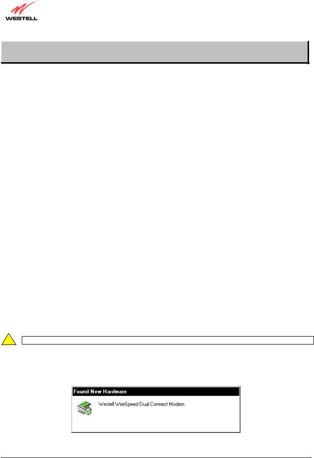
1.After you have connected the Westell Dual Connect Modem to your PC, the Found New Hardware window appears (Figure 4). In a few moments, the Add New Hardware Wizard window will open (Figure 5). Click
Next.
Figure 4. Windows 98
030-300372 Rev. A |
10 |
July 2003 |
User Guide |
Westell Dual Connect NAT Router with DMH Technology |
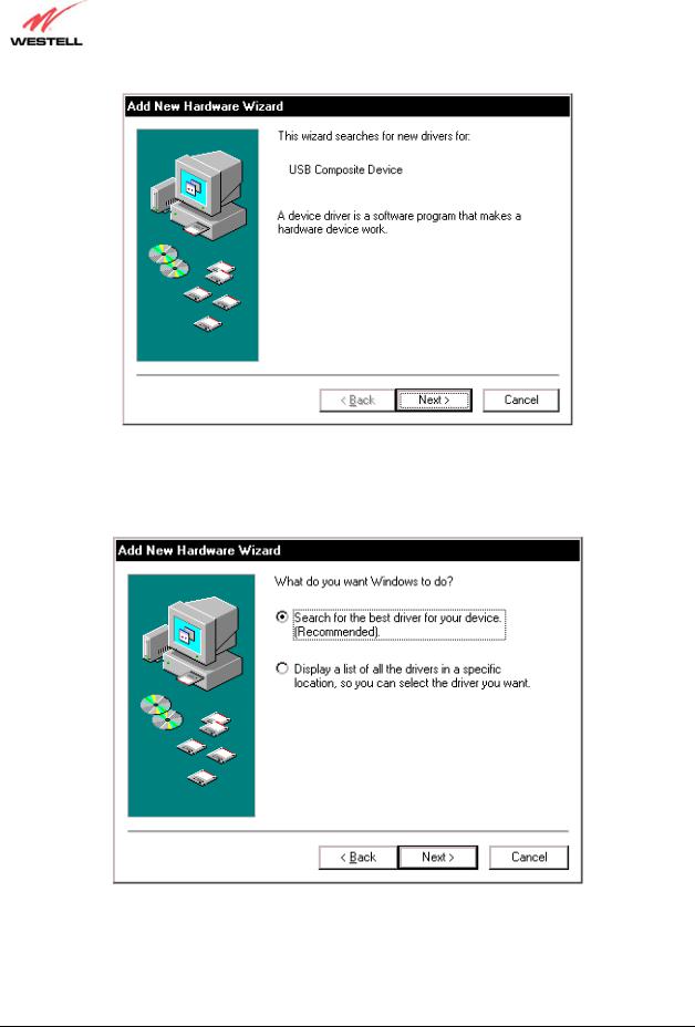
Figure 5. Add New Hardware
2.Windows 98: Click the option button for Search for the best driver for your device. (Recommended). See Figure 6. Click Next.
Figure 6. Windows 98
030-300372 Rev. A |
11 |
July 2003 |

User Guide |
Westell Dual Connect NAT Router with DMH Technology |
3.Windows 98: Select CD-ROM drive option. See Figure 7. Click Next. Windows will search for the driver.
Figure 7. Windows 98
4.Windows 98: Select option button The updated driver (Recommended) Westell Dual Connect Modem. See Figure 8. Click Next.
!Note: If Figure 8 does not appear at this step, and Figure 9 appears with the text ‘USB Composite device’, ‘C:\Windows\Inf\USB.Inf’, do not continue. Click Back to Step 3 and specify the location of the Westell CD-ROM.
Figure 8. Windows 98
030-300372 Rev. A |
12 |
July 2003 |

User Guide |
Westell Dual Connect NAT Router with DMH Technology |
5.Windows 98: Windows will display the location of the driver. See Figure 9. Click Next. Note: The drive “letter” may vary.
F:\WSTLVRTR.INF
Figure 9. Windows 98
6.Windows 98: Remove the Westell CD from the CD-ROM Drive. Next, insert the Windows operating system CD into the CD-ROM Drive. See Figure 10. Click OK.
Figure 10. Windows 98
7.Windows 98: The system will begin copying files (Figure 11).
Figure 11. Windows 98
030-300372 Rev. A |
13 |
July 2003 |

User Guide |
Westell Dual Connect NAT Router with DMH Technology |
8.Windows 98: Figure 12 may pop up, depending on how Windows 98 was installed on the computer. The installation of the Westell modem requires files that are supplied by Microsoft for Windows 98. If Figure 13 pops up, insert the Windows 98 Operating System CD into the computers CD-ROM drive, wait a moment for the CD to be recognized by the system, and then click on OK. The system should find the required files on the Windows 98 CD and automatically complete the installation.
Figure 12. Windows 98
If the Operating System CD is not available, or if Figure 12 pops up again, you will have to manually specify the location of the files. The required files may be stored on your hard drive. A common location for these files is "C:\Windows\Options\Cabs." Try specifying this path or the path to your CD-ROM drive (usually "D:\") by clicking the Browse… button in the Insert Disk screen. When you have specified the correct path, click on OK. The system will begin copying the files. See Figure 14.
NOTE: It is very important that the Windows 98 files be installed. Do not click on Cancel or Skip File in the dialogs, doing so will result in an improper installation and the modem will not function correctly.
Figure 13. Windows 98
030-300372 Rev. A |
14 |
July 2003 |

User Guide |
Westell Dual Connect NAT Router with DMH Technology |
9.Windows 98: The window below confirms that the PC has finished loading the drivers (Figure 14). Click
Finish.
Figure 14. Windows 98
10. Windows 98: Click Yes to restart your computer. See Figure 15.
Figure 15. Windows 98
Congratulations! You have completed the software installation for the USB drivers. After the computer has restarted, the Router is ready for use. You must now go to section 7.
030-300372 Rev. A |
15 |
July 2003 |
User Guide |
Westell Dual Connect NAT Router with DMH Technology |
6.3 Installing the USB Drivers for Windows ME
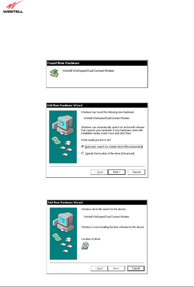
1.Windows ME: After you have connected the Dual Connect Modem to your PC, the Found New Hardware window appears (Figure 16). In a few moments, the Add New Hardware Wizard window appears (Figure 17). Click the option button for Automatic search for a better driver (Recommended). Click Next.
Figure 16. Windows ME
Figure 17. Windows ME
2.Windows ME: Windows will display the location of the driver. See Figure 18.
F:\WSTLVRTR.INF
Figure 18. Location of Hardware Device Driver
030-300372 Rev. A |
16 |
July 2003 |
User Guide |
Westell Dual Connect NAT Router with DMH Technology |
3.Windows ME: The window below confirms that the PC has finished loading the drivers. See Figure 19. Click
Finish.
Figure 19. Found New Hardware
4.Windows ME: When the System Settings Change screen appears, the USB drivers are installed properly. See Figure 20. Click Yes.
Figure 20. Restart the Computer
Congratulations! You have completed the software installation for the USB drivers. After the computer has restarted, the Router is ready for use. You must now go to section 7.
030-300372 Rev. A |
17 |
July 2003 |

User Guide |
Westell Dual Connect NAT Router with DMH Technology |
6.4 Installing the USB Driver for Windows 2000
1.Windows 2000: After you have connected the Westell Dual Connect Modem to your PC, the Found New Hardware window appears (Figure 21). In a few moments, the Found New Hardware Wizard window appears (Figure 22). Click Next.
Figure 21. Found New Hardware
Figure 22. Welcome to Install Device Driver
030-300372 Rev. A |
18 |
July 2003 |

User Guide |
Westell Dual Connect NAT Router with DMH Technology |
2.Windows 2000: The Install Hardware Device Drivers window appears. Select Search for a suitable driver for my device (recommended) See Figure 23. Click Next.
Figure 23. Search for Device Driver
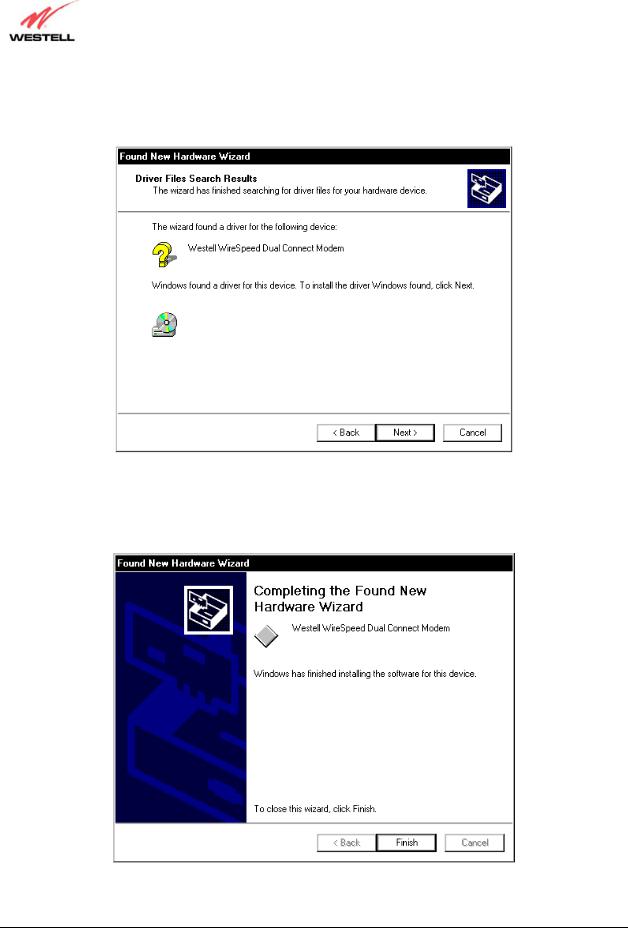
3.Windows 2000: The Driver Files Search Results window appears. Select the CD-ROM drives option See Figure 24). Click Next.
Figure 24. Locate Driver Files
030-300372 Rev. A |
19 |
July 2003 |
User Guide |
Westell Dual Connect NAT Router with DMH Technology |
4.Windows 2000: The Driver Files Search Results window appears (Figure 25). Click Next.
Note: The drive “letter” may vary.
F:\WSTLVRTR.INF
Figure 25. Driver Files Search Results
5.Windows 2000: The window below confirms that the PC has finished loading the drivers (Figure 26). Click
Finish.
Figure 26. Drivers Loaded
030-300372 Rev. A |
20 |
July 2003 |

User Guide |
Westell Dual Connect NAT Router with DMH Technology |
6.Windows 2000: When the System Settings Change screen appears, the USB drivers are installed properly. See Figure 27. Click Yes.
Figure 27. Restart Your Computer
Congratulations! You have completed the software installation for the USB drivers. After the computer has restarted, the Router is ready for use. You must now go to section 7.
6.5 Installing the USB Driver for Windows XP
1.Windows XP: After you have connected the Westell Dual Connect Modem to your PC, the Found New Hardware Wizard window will open. See Figure 28. Select option button Install the software automatically (Recommended). Click Next.
Figure 28. Windows XP
030-300372 Rev. A |
21 |
July 2003 |

User Guide |
Westell Dual Connect NAT Router with DMH Technology |
2.Windows XP: The window below confirms that the PC has finished loading the drivers (Figure 29). Click
Finish.
Figure 29. Windows XP
Congratulations! You have completed the software installation for the USB drivers. After the computer has restarted, the Router is ready for use. You must now go to section 7.
030-300372 Rev. A |
22 |
July 2003 |

User Guide |
Westell Dual Connect NAT Router with DMH Technology |
7. CONFIGURING THE ROUTER FOR INTERNET CONNECTION
To surf the Internet using your Westell Dual Connect NAT Router, you must set up your account profile, confirm your DSL sync, and establish a DHCP/PPP session with your Internet service provider (ISP). Refer to the Internet service provider’s installation manual to install the software required for your Internet connection. After you have connected to the Internet, you may use the Router’s Network Address Translation (NAT) feature to configure your Router for a specific NAT service, discussed later in this section.
NOTE: When viewing the screens, please note that the actual information displayed may vary.
7.1 Setting Up an Account Profile
At the Getting Started screen, click on next.
030-300372 Rev. A |
23 |
July 2003 |

User Guide |
Westell Dual Connect NAT Router with DMH Technology |
If you clicked on next, the following screen will be displayed. This screen will allow you to set up your account profile.
NOTE: Before you set up your account profile, you must obtain your Account ID, Account Password, and VPI/VCI values from your Internet service provider. You will use this information when you set up your account parameters. If you are at a screen and need help, click on the Help button to learn more about the screen.
Type in your account parameters. (Account parameters are required before connecting to the Internet.) Account Parameters include:
●Connection Name-the Connection Name is a word or phrase that you use to identify your account. (You may enter up 64 characters in this field.)
●Account ID-the Account ID is provided by your Internet Service Provider.
(You may enter up 255 characters in this field.)
●Account Password-the Account Password is provided by your Internet Service Provider. (You may enter up 255 characters in this field.)
When you enter your account parameters at the User Name screen, they will be displayed as shown in the screen below. Click next if you want your account parameters to take effect. Click on reset if you do not want the account parameters that you entered to take effect or if you want to re-enter the parameters.
030-300372 Rev. A |
24 |
July 2003 |

User Guide |
Westell Dual Connect NAT Router with DMH Technology |
Enter the VPI and VCI values (0 for VPI and 35 for VCI) you obtained from your Internet service provider. Click on next.
VPI = 0
VCI = 35
NOTE: Depending on your Internet Service Provider, the VPI/VCI screen may come pre-configured and it will be displayed here. In this case, you should not change any values in this screen. Click on next to go to the PROTOCOL screen.
030-300372 Rev. A |
25 |
July 2003 |

User Guide |
Westell Dual Connect NAT Router with DMH Technology |
Select the Protocol type that you obtained from your Internet Service Provider. Click on next.
NOTE: Depending on your Internet Service Provider, the PROTOCOL screen may come pre-configured and it will be displayed here. In this case, you will need to click on next to go to the SET-UP COMPLETE screen.
When the SET-UP COMPLETE screen appears, you have successfully completed your Account Profile setup. Click on done.
If you clicked on done, the following pop-up screen will be displayed. Click on OK. This will allow the modem to be reset and the new configuration will take effect.
030-300372 Rev. A |
26 |
July 2003 |
 Loading...