


G90-610060-20
Table of contents
 Loading...
PROLINE
P
ROLINE® G90-6110 (MODEL 6110)
®
G90-6100 (MODEL 6100)
USER GUIDE
Copyright © 2009 Westell, Inc. 1 August 2009

)
User Guide ProLine G90 (Models 6100, 6110
CONTENTS
1.
PRODUCT DESCRIPTION ..................................................................................................................................4
2. SAFETY INSTRUCTIONS...................................................................................................................................4
3. REGULATORY INFORMATION........................................................................................................................5
3.1 FCC Compliance Note...............................................................................................................................5
3.2 Canada Certification Notice.......................................................................................................................6
4. HARDWARE FEATURES....................................................................................................................................7
4.1 LED Indicators...........................................................................................................................................7
4.2 Cable Connectors and Locations................................................................................................................8
4.3 Connector Descriptions..............................................................................................................................8
4.4 Installation Requirements ..........................................................................................................................8
4.5 Before You Begin......................................................................................................................................9
4.6 Microfilters ................................................................................................................................................9
5. HARDWARE INSTALLATIONS.......................................................................................................................10
5.1 Connecting Your Modem to a DSL Network..........................................................................................10
6. INSTALLING THE USB DRIVERS...................................................................................................................12
6.1 Installing the USB Driver for Windows 2000..........................................................................................12
6.2 Installing the USB Driver for Windows XP.............................................................................................16
6.3 Installing the USB Driver for Windows Vista™ .....................................................................................17
7. ACCESSING YOUR MODEM...........................................................................................................................18
7.1 Logging on to Your Modem....................................................................................................................18
7.2 Configuring Your Internet Connection Using the Installation Wizard ....................................................19
7.3 Configuring Your Internet Connection Manually....................................................................................23
7.4 Confirming Your Internet Connection.....................................................................................................26
7.5 Disconnecting from an Internet Session ..................................................................................................27
7.6 Changing the Administration Password...................................................................................................28
8. SETTING UP MACINTOSH OS X.....................................................................................................................29
8.1 Opening the System Preference Screen...................................................................................................29
8.2 Choosing the Network Preferences..........................................................................................................29
8.3 Creating a New Location .........................................................................................................................30
8.4 Naming the New Location.......................................................................................................................30
8.5 Selecting the Ethernet Configuration.......................................................................................................30
8.6 Checking the IP Connection ....................................................................................................................31
8.7 Accessing Your Modem ..........................................................................................................................31
9. BASIC CONFIGURATION ................................................................................................................................33
10. HOME..................................................................................................................................................................34
10.1 Broadband Connection Panel...................................................................................................................34
030-300564 Rev A 2 August 2009

)
User Guide ProLine G90 (Models 6100, 6110
10.2 Quick Links Panel....................................................................................................................................35
10.3 My Network Panel...................................................................................................................................36
10.4 Services Panel..........................................................................................................................................36
11. MY NETWORK...................................................................................................................................................37
11.1 Network Devices......................................................................................................................................37
11.2 Network Summary...................................................................................................................................39
12. SECURITY ..........................................................................................................................................................40
12.1 Security Level..........................................................................................................................................40
12.2 Security Services......................................................................................................................................42
12.3 Change Password.....................................................................................................................................56
12.4 Security Log.............................................................................................................................................57
13. ADVANCED........................................................................................................................................................59
13.1 Version Data............................................................................................................................................59
13.2 Diagnostics...............................................................................................................................................60
13.3 LAN (Local Area Network).....................................................................................................................78
13.4 WAN (Wide Area Network)....................................................................................................................84
13.5 Single Static IP.........................................................................................................................................98
13.6 Restart....................................................................................................................................................101
14. TECHNICAL SUPPORT INFORMATION......................................................................................................102
15. PRODUCT SPECIFICATIONS.........................................................................................................................102
16. SOFTWARE LICENSE AGREEMENT............................................................................................................103
17. PUBLICATION INFORMATION.....................................................................................................................105
030-300564 Rev A 3 August 2009
)
User Guide ProLine G90 (Models 6100, 6110
1. PRODUCT DESCRIPTION
The Westell
®
ProLine® G90 DSL modem provides reliable, high-speed, Internet access to your existing home or
office phone line. Your ADSL connection is “always-on” ending the hassles of dial-up modems and busy signals.
Installation is easy... no tools... no headaches. Simply connect the hardware, apply power, and perform the simple
software configuration for your Modem and you are on the Internet.
This DSL modem is capable of data rates hundreds of times faster than a traditional analog modem. But unlike
analog modems, Westell’s DSL modem allows you to use the same phone line for simultaneous voice/fax
communications and high-speed Inter net access, eliminating the need for dedicated phone lines for voice and data
needs.
®
Hereafter, the Westell
This modem is powered by an ENERGY STAR
ProLine® G90 DSL modem will be referred to as the “modem.”
®
qualified adapter.
2. SAFETY INSTRUCTIONS
• Never install any telephone wiring during a lightning storm.
• Never install telephone jacks in wet locations unless the jack is specifically designed for wet locations.
• Never touch non-insulated telephone wires or terminals unless the telephone line has been disconnected at
the network interface.
• Use caution when installing or modifying telephone lines.
WARNING
Risk of electric shock. Voltages up to 140 Vdc (with reference to
ground) may be present on telecommunications circuits.
030-300564 Rev A 4 August 2009

)
User Guide ProLine G90 (Models 6100, 6110
3. REGULATORY INFORMATION
3.1 FCC Compliance Note
This equipment has been tested and found to comply with the limits for a Class B digital device, pursuant to Part 15
of the Federal Communication Commission (FCC) Rules. These limits are designed to provide reasonable protection
against harmful interference in a residential installation. This equipment generates, uses, and can radiate radio
frequency energy, and if not installed and used in accordance with the instructions, may cause harmful interference
to radio communications. However, there is no guarantee that interference will not occur in a particu lar installation.
If this equipment does cause harmful interference to radio or television reception, which can be determined by
turning the equipment OFF and ON, the user is encouraged to try to correct the interference by one or more of the
following measures:
• Reorient or relocate the receiving antenna.
• Increase the separation between the equipment and the receiver.
• Connect the equipment to a different circuit from that to which the receiver is connected.
• Consult the dealer or an experienced radio/TV technician for help.
PART 68 - COMPLIANCE REGISTRATION
This equipment (Models 6100, 6110) complies with Part 68 of the FCC rules and the requirements adopted by the
ACTA. A label on the bottom of this equipment contains, among other information, the Ringer Equivalence Number
(REN) and the product identifier. For products approved after July 23, 2001 the product identifier is in the format
US:AAAEQ##TXXXX. The digits represented by ## are the REN without a decimal point (e.g. 03 is a REN of 0.3).
The REN is used to determine the number of devices that may be connected to a telephone line. For earlier products,
the REN is separately shown on the label. If requested, this number must be provided to the telephone company.
Excessive RENs on a telephone line may result in the devices not ringing in response to an incoming call. In most,
but no all areas, the sum of RENs should not exceed five (5.0). To be certain of the number of devices that may be
connected to a line, as determined by the total RENs, contact the local telephone company.
This equipment is designated to connect to the telephone network or premises wiring using a compatible modular
jack that is Part 68 compliant. An FCC compliant telephone cord and modular plug is provided with the equipment.
See the Installation Information section of this User Guide for details.
A plug and jack used to connect this equipment to the premises w iring an d telephone network must comply with the
applicable FCC Part 68 rules and requirements adopted by the ACTA. A compliant telephone cord and modular plug
is provided with this product. It is designed to be connected to a compatible modular jack that is also compliant. See
installation instruction for details.
If this terminal equipment (Models 6100, 6110) causes harm to the telephone network, the telep hone company may
request you to disconnect the equipment until the problem is resolved. The telephone company will notify you in
advance if temporary discontinuance of service is required. If advance notification is not practical, the telephone
company will notify you as soon as possible. You will be advised of your right to file a complaint with the FCC if
you believe such action is necessary.
If you experience trouble with this equipment (Models 6100, 6110), do not try to repair the equipment yourself. The
equipment cannot be repaired in the field and must be returned to the manufacturer. Repairs to certified equipment
should be coordinated by a represen tative, and designated by the supplier. Refer to section 12 in this User Guide for
further details.
The telephone company may make changes to their facilities, equipment, operations, or p rocedures that could affect
the operation of this equipment. If this happens, the telephone company will provide advan ce notice in ord er for you
to make the modifications necessary to maintain uninterrupted service.
030-300564 Rev A 5 August 2009

)
User Guide ProLine G90 (Models 6100, 6110
If your home has specially wired alarm equipment connected to the telephone line, ensure that the installation of th is
equipment (Models 6100, 6110) does not disable your alarm equipment. If you have questions about what will
disable alarm equipment, consult your telephone company or a qualified installer.
This equipment cannot be used on public coin phone service provided by the telephone company. Connection of this
equipment to party line service is subject to state tariffs.
3.2 Canada Certification Notice
The Industry Canada label identifies certified equipment. This certification means that the equipment meets certain
telecommunications network protective, operations and safety requirements as prescribed in the appropriate
Terminal Equipment Technical Requirements document(s). The department does not guarantee the equipment will
operate to the user’s satisfaction.
This equipment meets the applicable Industry Canada Terminal Equipment Technical Specification. This is
confirmed by the registration number. The abbreviation, IC, before the registration number signifies that registration
was performed based on a Declaration of Conformity indicating that Industry Canada technical specification were
met. It does not imply that Industry Canada approved the equipment. The Ringer Equivalence Number (REN) is 0.0.
The Ringer Equivalence Number that is assigned to each piece of terminal equipment provides an indication of the
maximum number of terminals allowed to be connected to a telephone interface. The termination on an interface
may consist of any combination of devices subject only to the requirement that the su m of the Ringer Equivalence
Numbers of all the devices does not exceed five.
Before installing this equipment, users should ensure that it is permissib le to be connected to the facilities of the
local Telecommunication Company. The equipment must also be installed using an acceptable method of
connection. The customer should be aware that compliance with the above conditions may not prevent degrad ation
of service in some situations. Connection to a party line service is subject to state tariffs. Contact the state public
utility commission, public service commission, or corporation commission for information.
If your home has specially wired alarm equipment connected to the telephone line, ensure that the installation of th is
equipment (Models 6100, 6110) does not disable your alarm equipment. If you have questions about what will
disable alarm equipment, consult your telephone company or a qualified installer.
If you experience trouble with this equipment (Models 6100, 6110), do not try to repair the equipment yourself. The
equipment cannot be repaired in the field and must be returned to the manufacturer. Repairs to certified equipment
should be coordinated by a represen tative, and designated by the supplier. Refer to section 12 in this User Guide for
further details.
The termination on an interface may consist of any combination of devices subject only to the requirement that the
sum of the Ringer Equivalence Nu mbers of all the devices does not exceed five.
Users should ensure, for their own protection, that the electrical ground connections of the power utility, teleph one
lines, and internal, metallic water pipe system, if present, are connected together. This precaution may be
particularly important in rural areas.
CAUTION
Users should not attempt to make such connections themselves, but should contact the
appropriate electrical inspection authority, or electrician, as appropriate.
030-300564 Rev A 6 August 2009

)
User Guide ProLine G90 (Models 6100, 6110
4. HARDWARE FEATURES
4.1 LED Indicators
This section explains the LED States and Descriptions. LED indicators are used to verify the unit’s operation and
status.
LED States and Descriptions
LED State Description
Modem power is ON.
Modem power is OFF.
POST (Power On Self Test), Failure (not bootable) or Devi ce
Malfunction. Note: The Power LED should be red no longer than
two seconds after the power on self test passes.
Powered device is connected to the associated port (includes
devices with wake-on LAN capability where slight voltage is
supplied to an Ethernet connection).
Note: When using the optional upli n k p ort (E1), Ethernet LAN
connection is limited to E2, E3, and E4.
10/100 Base-T LAN activity is present (traffic in either direction)
Modem power is OFF, no cable or no powered device is
connected to the associated port.
USB link established.
USB LAN activity present (traffic in either direction).
No USB link established.
Good DSL link.
DSL attempting to sync.
Modem is in safeboot mode.
Modem power is OFF.
Internet link established. With DSL up, the modem has a WAN IP
address from IPCP or DHCP; or a static IP is configured; or PPP
negotiation has successfully completed (if used) and no traffic is
detected.
IP connection established and IP Traffic is passing through device
(in either direction). Note: If the IP or PPP session is dropped due
to an idle timeout, the light will remain solid green, if a DSL
connection is still present. If the session is dropped for any other
reason, the light is turned OFF. The light will turn red when it
attempts to reconnect and DHCP or PPP fails).
Device attempted to become IP connected and failed (no DHCP
response, no PPP response, PPP authentication failed, no IP
address from IPCP, etc.).
Modem power is OFF or the DSL connection is not present.
POWER
ETHERNET
USB
DSL
INTERNET
Solid Green
OFF
Solid Red
Solid Green
Flashing Green
OFF
Solid Green
Flashing Green
OFF
Solid Green
Flashing Green
Solid Amber
OFF
Solid Green
Flashing Green
Solid Red
OFF
030-300564 Rev A 7 August 2009
)
r
r
r
User Guide ProLine G90 (Models 6100, 6110
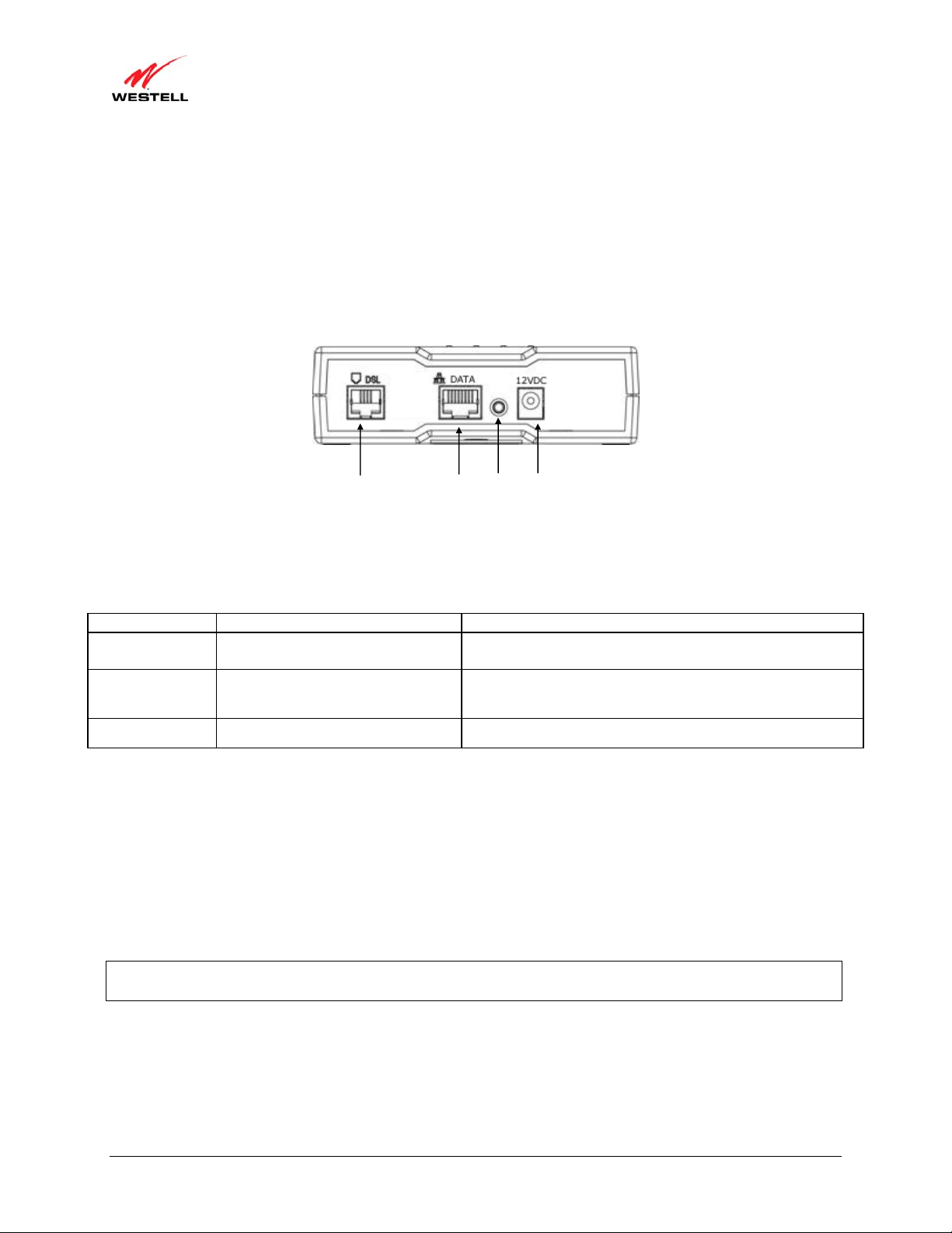
4.2 Cable Connectors and Locations
• DSL connector (RJ-11)
• Ethernet (RJ-45) connector DATA port
• Reset push button
• Power connector (12 VDC) barrel
Model 6100 and Model 6110 - Rear View
DSL Line
Connecto
Ethernet
Connecto
Reset
Power
Connecto
4.3 Connector Descriptions
The following chart displays the modem’s connector types.
AME TYPE FUNCTION
N
DSL Modular 6-pin (RJ-11) DSL jack
DATA Modular 8-pin (RJ-45) Ethernet jack
Connects the modem to a telephone jack that has active DSL
service or to the DSL port of a POTS splitter.
Connects the modem to a PC or Hub via 10/100 BaseT
Ethernet.
12VDC Barrel connector Connects the 12 VDC power connector to an AC wall jack.
4.4 Installation Requirements
This section explains the hardware installation procedures for installing your modem.
To install the modem, you will need the following:
• Active DSL line
• Network Interface Card (NIC) installed in your PC, or
• Available USB port installed in your PC
IMPORTANT: Please wait until you have received notification from your Internet service provider (ISP) that your
DSL line has been activated before installing your modem.
030-300564 Rev A 8 August 2009

)
User Guide ProLine G90 (Models 6100, 6110
4.5 Before You Begin
Make sure that your kit contains the following items:
• Westell ProLine G90 DSL modem
• Power Supply
• Y-cable comprising:
o Built-in 10/100 BaseT Ethernet cable—labeled PC/Ethernet, yellow
o Built-in USB cable—labeled PC/USB, blue
• RJ-11 Phone cable
• CD-ROM containing User Guide in PDF format
4.6 Microfilters
DSL signals must be blocked from reaching each telephone, answering machine, fax machine, computer modem, or
any similar conventional device. Failure to do so may degrade telephone voice quality and DSL performance. Install
a microfilter if you desire to use the DSL-equipped line jack for telephone, answering machine, fax machine, or
other telephone device connections. Microfilter installation requires no tools or telephone rewiring. Just unplug the
telephone device from the baseboard or wall mount and snap in a microfilter; next, snap in the telephone device.
You can purchase microfilters from your local electronics retailer, or contact the original provider of your DSL
equipment.
030-300564 Rev A 9 August 2009

)
User Guide ProLine G90 (Models 6100, 6110
5. HARDWARE INSTALLATIONS
The following instructions explain how to install your modem using 10/100 Base-T Ethernet or USB connections.
Before you begin, please read the following notes:
NOTE:
1. If your Ethernet card does not auto-negotiate, set it to half duplex. Refer to the Ethernet card manufacturer’s
instructions for installing and configuring your Ethernet card.
2. If you are using your modem in conjunction with an Ethernet Hub or Switch, refer to the manufacturer’s
instructions for proper installation and configuration.
3. When using a microfilter, confirm that the DSL RJ-11 phone cable is connected to the DSL port of the DSL/HPN
non-filtered jack.
4. It is recommended that you use a surge suppressor to protect equipment attached to the power supply. Use only
the power supply provided with your kit.
5. Depending on the installation method you are using, additional Ethernet cables may be required. Ethernet cables
and DSL filters can be purchased at your local computer hardware retailer.
5.1 Connecting Your Modem to a DSL Network
To connect your modem to a network provisioned with activ e DSL service, please follow these steps:
1. Connect the DSL phone from the connector marked DSL on the rear panel of the modem to the teleph one wall
jack provisioned with DSL service. Please use the DSL phone cable that was provided with your kit.
IMPORTANT: Plug the RJ-11 DSL phone cable from the modem into the DSL port of the microfilter plugged
into the telephone jack at the wall.
2. Plug the small end of the power supply cord into the connector marked 12VDC on the rear panel of the modem.
Plug the other end of the power supply into an AC wall socket.
3. Check to see if the POWER LED is solid green. Solid green indicates that the modem is functioning properly.
4. Check to see if the DSL LED is solid green. If it is solid green, DSL is functioning properly.
5. Log on to your account, and establish an Internet connection, as explained later in section 7, “Accessing Your
Modem.”
6. Check to see if the modem’s INTERNET LED is solid green. Solid green indicates that the Internet link has
been established. (Flashing green indicates the presence of IP traffic.)
Congratulations! You have completed the installation. Now, go to section 5.1.1, “Connecting Ethernet Devices to Your
Modem,” or section 5.1.2, “Connecting USB Devices to Your Modem,” depending on your PC’s configuration.
030-300564 Rev A 10 August 2009

)
User Guide ProLine G90 (Models 6100, 6110
5.1.1 Connecting Ethernet Devices to Your Modem
To network computers in your home or office to your modem using an Ethernet installation, please follow these
steps:
1. Ensure that you have connected your modem to your broadband service using the installation method explained
earlier in section 5.1, “Connecting Your Modem to a DSL Network.”
2. Obtain an Ethernet cable. Connect the Ethernet cable from the DATA port on the rear panel of the modem to
the Ethernet port on your computer.
3. Check to see if the modem’s ETHERNET LED is solid green. Solid green indicates that the Ethernet
connection is functioning properly. Check the ETHERNET LED for each Ethernet jack to which you are
connected.
Congratulations! You have completed the connection. Now, go to section 7, “Accessing Your Modem,” to access your
modem’s Web pages.
5.1.2 Connecting USB Devices to Your Modem
It is recommended that you connect your modem via Eth ernet connections. How ever, if you choose to connect your
computer via USB, please follow the instructions in this section.
IMPORTANT: The USB installation will not function for Macintosh computers. Macintosh users will need to
install the modem via Ethernet connection. Refer to section 5.1.1, “Connecting Ethernet Devices to Your Modem,”
for Ethernet installation instructions.
To network a computer in your home or office to your modem using a USB connection, please follow these steps:
1. Ensure that you have connected your modem to your broadband service using one the installation method
explained earlier in section 5.1, “Connecting Your Modem to a DSL Network.”
2. Insert the CD-ROM provided with your kit into the CD-ROM drive of the PC that will connect via USB.
3. Use the Y-cable provided with your kit. At the “Y” end of the cable, plug the USB jack (labeled PC/USB, blue)
into the USB port on your computer. Then, at the other end of the Y-cable, plug the Ethernet jack (labeled
PC/ETHERNET, yellow) into the Ethernet connector marked DATA on the rear panel of the modem.
4. Plug the small end of the power supply cord into the connector marked 12VDC on the rear panel of the modem.
Plug the other end of the power supply into an AC wall socket.
5. Complete the instructions outlined in section 6, “Installing the USB Drivers.” Then, return to this section to
complete the remaining step.
6. After the USB drivers have been installed, check to see if the USB LED is solid green. Solid green indicates that the
USB connection is functioning properly.
Congratulations! You have completed the USB hardware installation. Now, go to section 7, “Accessing Your
Modem,” to access your modem’s Web pages.
030-300564 Rev A 11 August 2009
)
User Guide ProLine G90 (Models 6100, 6110
6. INSTALLING THE USB DRIVERS
This section explains how to install the USB drivers for your modem. If you are using only an Ethernet connection,
USB driver installation is not necessary. The Microsoft Plug and Play (PnP) auto-detect feature recognizes when
new hardware has been installed. After you connect the modem to the PC, the modem will be detected
automatically.
IMPORTANT: Make sure that the CD-ROM provided with your kit is inserted into the PC’s CD-ROM drive before
connecting the USB jack, as explained in section 5.1.2, “Connecting USB Devices to Your Modem .”
Determine which operating system is installed on your PC, and then follow the USB driver instructions that match
your operating system. The following table provides a reference to the USB driver installation instructions. After
you have completed the USB driver installation, return to section 5.1.2, “Connecting USB Devices to Your
Modem,” to complete the USB hardware installation instructions.
Your Operating System Refer to this section for USB driver instructions
Windows 2000 6.1. Installing the USB Driver for Windows 2000
Windows XP 6.2. Installing the USB Driver for Windows XP
Windows Vista™ 6.3. Installing the USB Driver for Windows Vista™
6.1 Installing the USB Driver for Windows 2000
To install the USB driver for Windows 2000, please follow these steps:
IMPORTANT: Confirm that the CD-ROM provided with the modem kit is inserted into the PC’s CD-ROM drive
before beginning this installation.
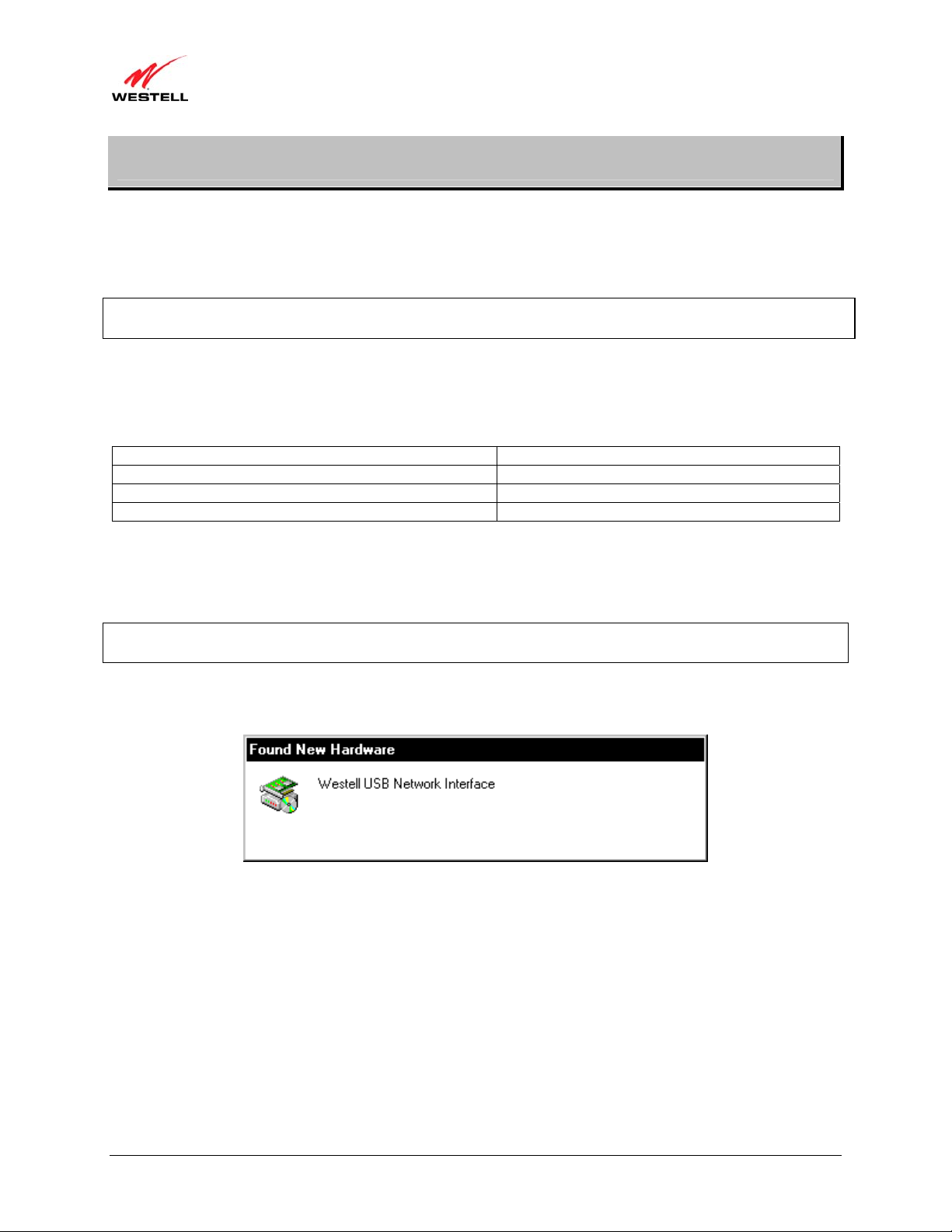
1. Windows 2000: After you connect the modem to your PC, the Found New Hardware window will appear
(Figure 1). After a brief delay, the Found New Hardware Wizard will appear (Figure 2). Click Next.
Figure 1. Windows 2000
030-300564 Rev A 12 August 2009
)
User Guide ProLine G90 (Models 6100, 6110
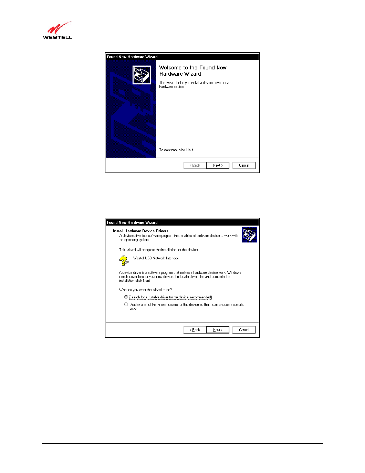
2. Windows 2000: The Install Hardware Device Drivers window will appear (Figure 3). Select Search for a
suitable driver for my device (recommended). Click Next.
Figure 2. Windows 2000
Figure 3. Windows 2000
030-300564 Rev A 13 August 2009
)
User Guide ProLine G90 (Models 6100, 6110
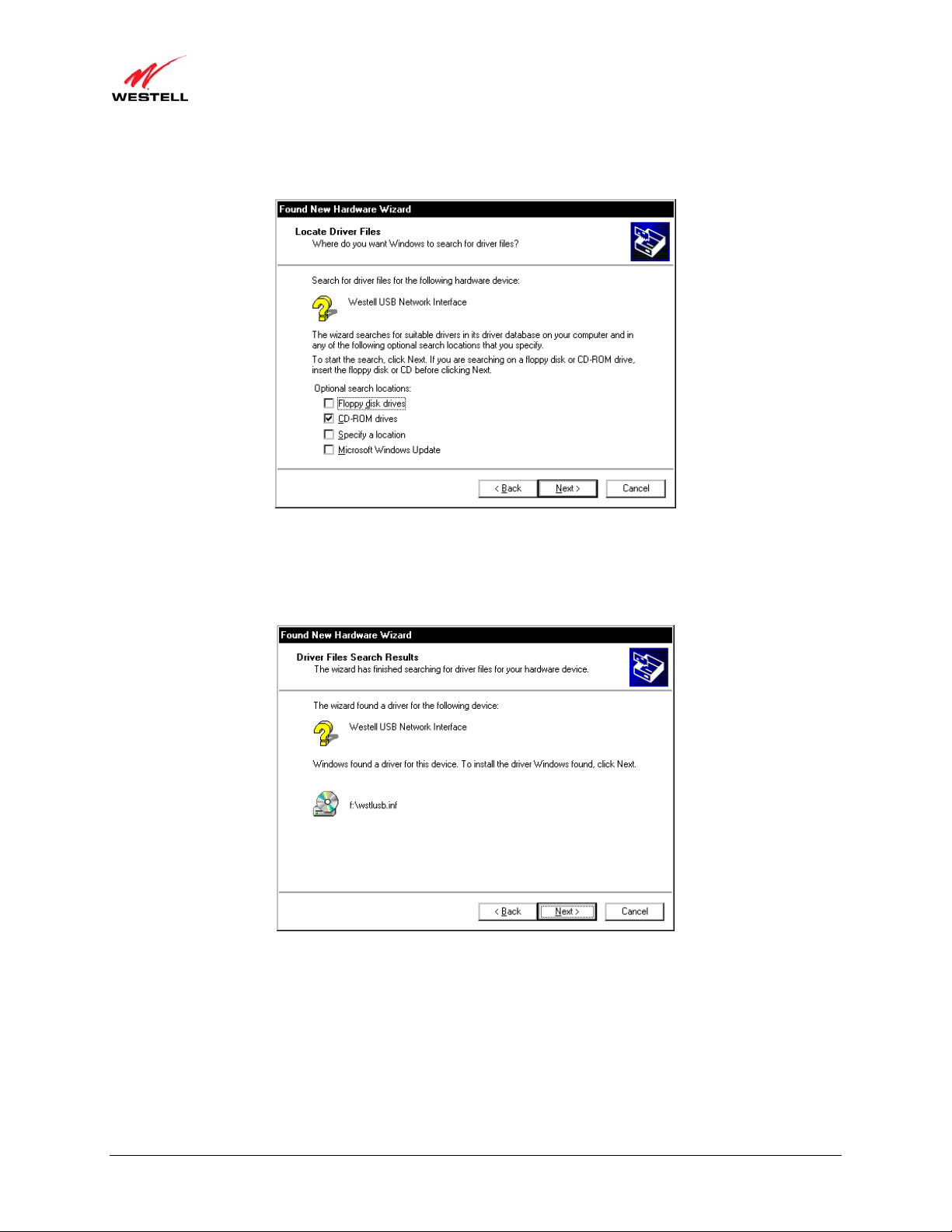
3. Windows 2000: The Locate Driver Files window will appear. Select CD-ROM drives (Figure 4). Click Next.
Figure 4. Windows 2000
4. Windows 2000: The Driver Files Search Results window will appear (Figure 5). Note the drive “letter” may
vary. Click Next.
Figure 5. Windows 2000
030-300564 Rev A 14 August 2009
)
User Guide ProLine G90 (Models 6100, 6110
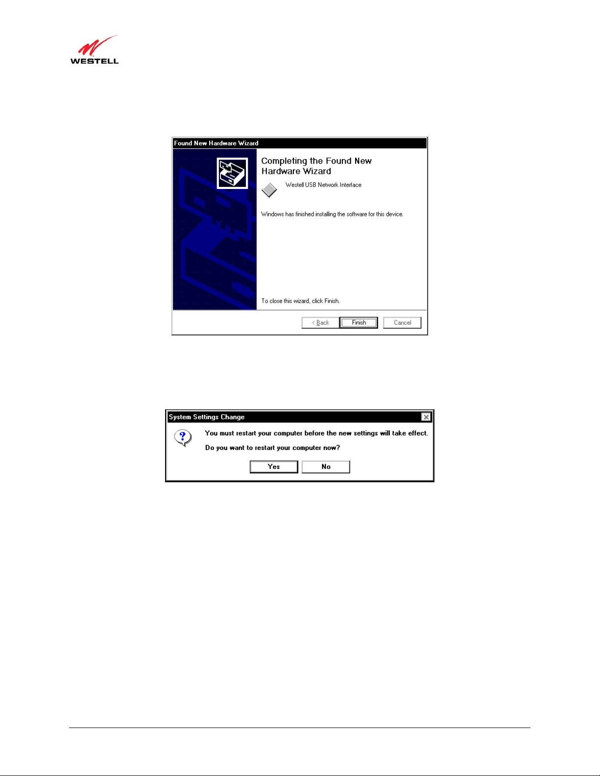
5. Windows 2000: The window below confirms that the PC has finished loading the drivers (Figure 6). Click
Finish.
Figure 6. Windows 2000
6. Windows 2000: When the System Settings Change screen appears, the USB d rivers are installed properly
(Figure 7). Click Yes to restart your computer.
Figure 7. Windows 2000
Congratulations! You have completed the software installation for the USB drivers. Now, return to section 5.1.2,
“Connecting USB Devices to Your Modem,” to complete the hardware installation instructions.
030-300564 Rev A 15 August 2009
)
User Guide ProLine G90 (Models 6100, 6110
6.2 Installing the USB Driver for Windows XP
To install the USB driver for Windows XP, please follow these steps:
IMPORTANT: Confirm that the CD-ROM provided with the modem kit is inserted into the PC’s CD-ROM drive
before beginning this installation.
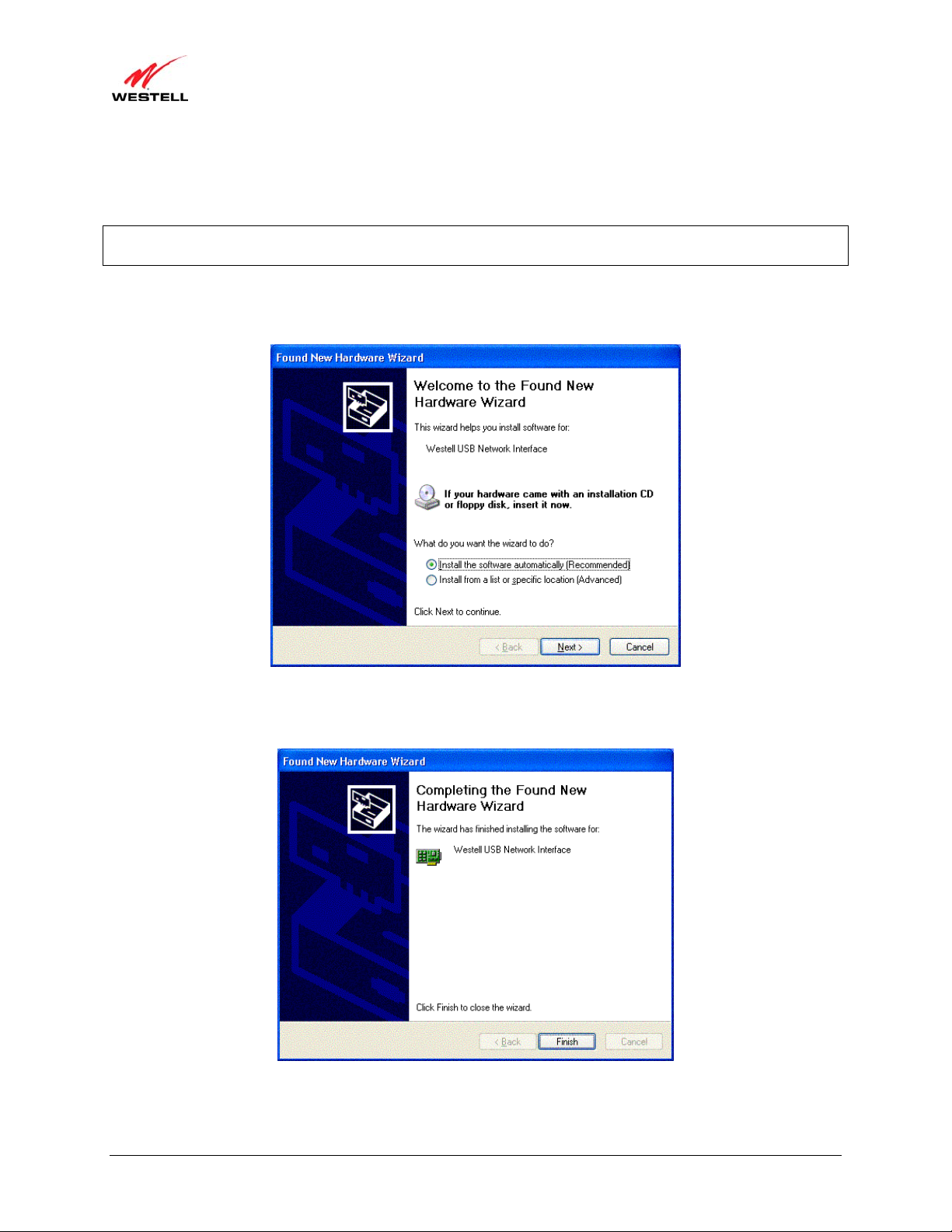
1. Windows XP: After you connect the modem to your PC, the following screen will appear (Figure 8). Select
Install the software automatically (Recommended). Click Next.
Figure 8. Windows XP
2. Windows XP: The window below confirms that the PC has finished loading the drivers (Figure 9). Click Finish.
Figure 9. Windows XP
Congratulations! You have completed the software installation for the USB drivers. Now return to section 5.1.2,
“Connecting USB Devices to Your Modem,” to complete the hardware installation instructions.
030-300564 Rev A 16 August 2009
)
User Guide ProLine G90 (Models 6100, 6110
6.3 Installing the USB Driver for Windows Vista™
To install the USB driver for Windows Vista™, please follow these steps:
IMPORTANT: Confirm that the CD-ROM provided with the modem kit is inserted into the PC’s CD-ROM drive
before beginning this installation.
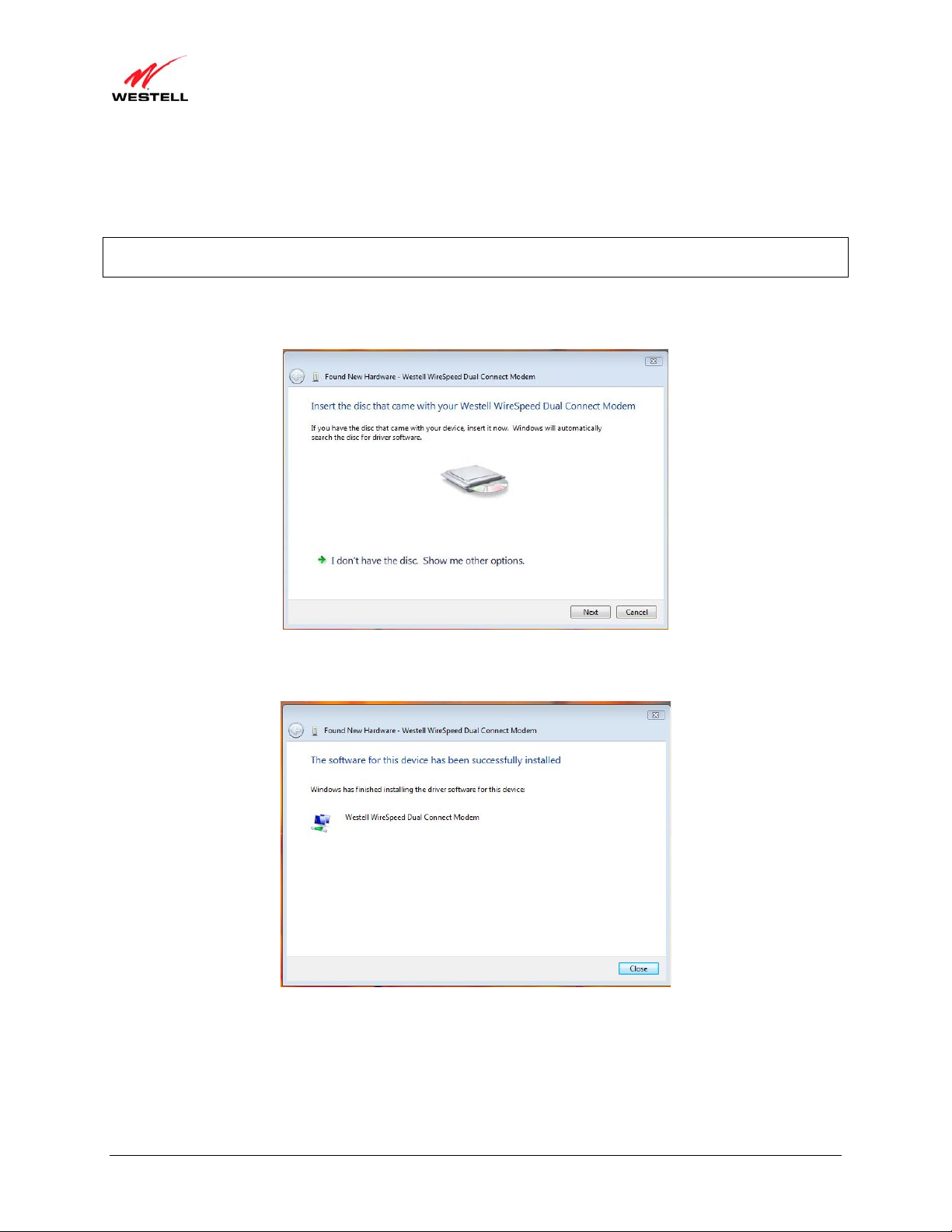
1. Windows Vista™: After you connect the modem to your PC, the following Found New Hardware screen will
appear (Figure 10). Click Next.
Figure 10. Windows Vista
2. Windows Vista™: The window below confirms that the PC has finished loading the drivers (Figure 11). Click
Close.
Figure 11. Windows Vista
Congratulations! You have completed the software installation for the USB drivers. Now return to section 5.1.2,
“Connecting USB Devices to Your Modem,” to complete the hardware installation instructions.
030-300564 Rev A 17 August 2009
)
User Guide ProLine G90 (Models 6100, 6110
7. ACCESSING YOUR MODEM
7.1 Logging on to Your Modem
This section explains the logon procedures for your modem. These procedures should be used any time you want to
access or make changes to your modem’s configurations or firewall settings.
IMPORTANT: Your modem is capable of automatically sensing protocol type (DHCP or PPPoE). This process is
designed to start after you have connected your modem to your network. To access your modem’s Web pages, your
PC must be configured for DHCP. Refer to your Windows he lp screen for information on configuring your
computer for DHCP. At your PC, click Start, then Help to access the Windows help screen.
Your ISP determines the type of protocol you will use to connect to the Internet. Routed IP allows you to connect to
your ISP equipment without first having to identify yourself (authenticate) with your ISP. PPPoE requires that you
authenticate (type an account ID and password) before obtaining an Internet connection. After automatic protocol
detection starts, the modem will determine which protocol you will use for your Internet connection.
To log on to your modem, start your Web browser, and type the following IP address in the browser’s address bar:
http://192.168.1.1
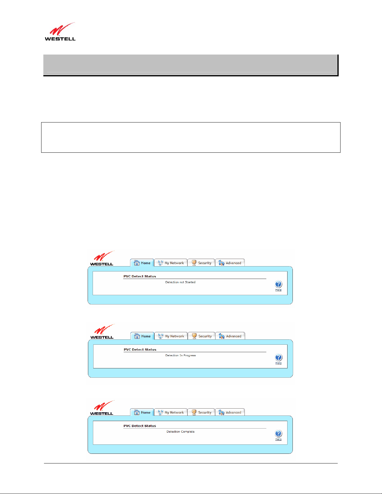
After you have typed the URL address, press Enter on your keyboard. If your modem has the Automatic PVC
Detection feature enabled (optional), you will see this screen while the modem detects and configures the WAN
connection.
The detection process will then begin as shown in the following screen.
Once the detection process is complete, you will see the following screen.
030-300564 Rev A 18 August 2009

)
User Guide ProLine G90 (Models 6100, 6110
7.1.1 Connecting to the Internet via Routed IP Protocol
If Automatic WAN Protocol Detection finds that your ISP’s server is DHCP, the ISP’s DHCP server will send your
modem a WAN IP address. A WAN IP address indicates that you have established a connection with your ISP.
Routed IP allows you to connect to your ISP equipment without first having to identify yourself (authenticate) with
your ISP. Once your modem has obtain ed a WAN IP address, you do not need to configure any additional settings
Congratulations! You have completed the modem’s Automatic WAN Protocol Detection process. Now, go to
section 7.4, “Confirming Your Internet Connection,” to confirm your Internet connection.
7.1.2 Connecting to the Internet via PPPoE Protocol
Some ISPs require that you identify yourself using PPP (Point-to-Point Protocol) authentication be fore obtaining an
Internet connection. To connect to the Internet for the first time via PPP, go to one of the following sections:
• Section 7.2, “Configuring Your Internet Connection Using the Installation Wizard,” for details on
connecting to the Internet using the modem’s built-in Installation Wizard. Use this method for simple, lessdetailed configuration process.
• Section 7.3, “Configuring Your Internet Connection Manually,” for details on connecting to the Internet
using a manually set up connection. Use this method for a more detailed configuration process.
7.2 Configuring Your Internet Connection Using the Installation Wizard
To connect to the Internet using the modem’s built-in Installation Wizard, please follow these steps:
1. Click the Add/Edit Connection
Started window will appear.
link in the Broadband Connection panel of the Home screen. The Getting
030-300564 Rev A 19 August 2009

)
User Guide ProLine G90 (Models 6100, 6110
2. Click next. The User Name window will appear, requesting information that will allow the modem to make a
connection to your ISP. This information is stored in your modem.
3. Type in the following information in the fields provided:
• Connection Name: This is a description of the default connection profile that your modem will use.
You may use the default or assign a new description.
• Account ID: This is supplied by your ISP. This is a text string which uniquely identifies you with your
ISP.
• Account Password: This is supplied by your ISP. This is a key phrase or text string that verifies your
identity to the ISP.
030-300564 Rev A 20 August 2009
)
User Guide ProLine G90 (Models 6100, 6110
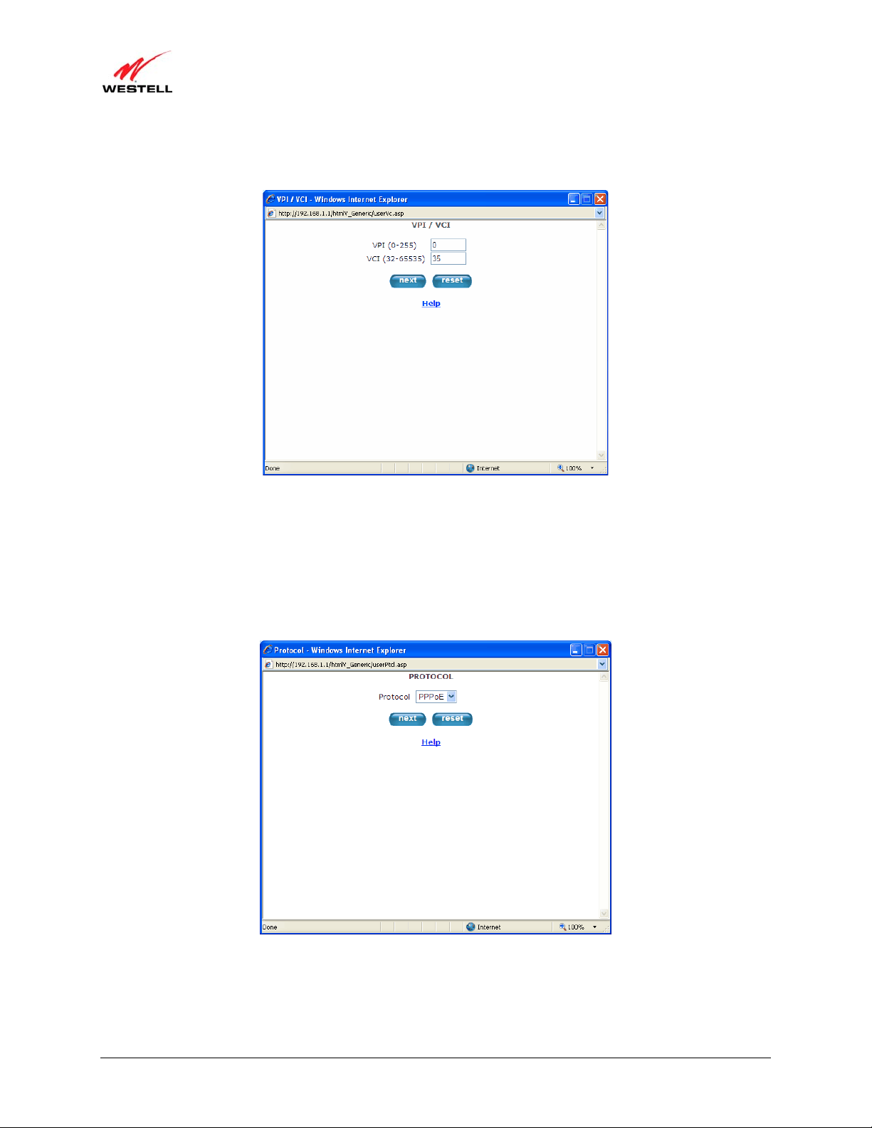
4. Click next. The VPI/VCI window will appear, requesting information that will allow the modem to establish a
communications channel to the ISP.
5. Type in the following information in the fields provided:
• VPI (0-255): This is Virtual Path Indicator. This value is supplied by your ISP.
• VCI (32-65535): This is the Virtual Channel Indicator. This value is supplied by your ISP.
6. Click next. The PROTOCOL window appears, requesting a networking protocol to use when communicating
with the ISP.
7. Click the drop-down menu to select a protocol: PPPoA, PPoE, or Bridge. This information is provided by your
ISP.
030-300564 Rev A 21 August 2009

)
User Guide ProLine G90 (Models 6100, 6110
8. Click the next button. The SET-UP COMPLETE window will appear, signifying that you have successfully
established a connection profile.
9. Click the done button. The Connection Overview screen appears. The Installation Wizard is now done.
10. Click Home in the main menu to exit the process completely.
Congratulations! You have com pl eted configuring your Internet connection using the Installation Wizard. Now, go
to section 7.4, “Confirming Your Internet Connection,” to confirm your Internet connection.
030-300564 Rev A 22 August 2009
)
User Guide ProLine G90 (Models 6100, 6110
7.3 Configuring Your Internet Connection Manually
Your modem allows you to set up connection profiles for PPP authentication with your ISP. A connection profile
contains your account ID and password (provided by your ISP), and several connection options that you can specify
for your profile. The account ID and password are used for each connection profile that you set up. Connection
profiles can be associated with specific service settings, such as firewall settings or NAT services, enabling you to
customize your modem for specific users.
IMPORTANT: Before setting up a connection profile, confirm that you have an Account ID and Account Password
from your ISP.
To connect to the Internet manually by setting up a PPPoE connection profile, please follow these steps:
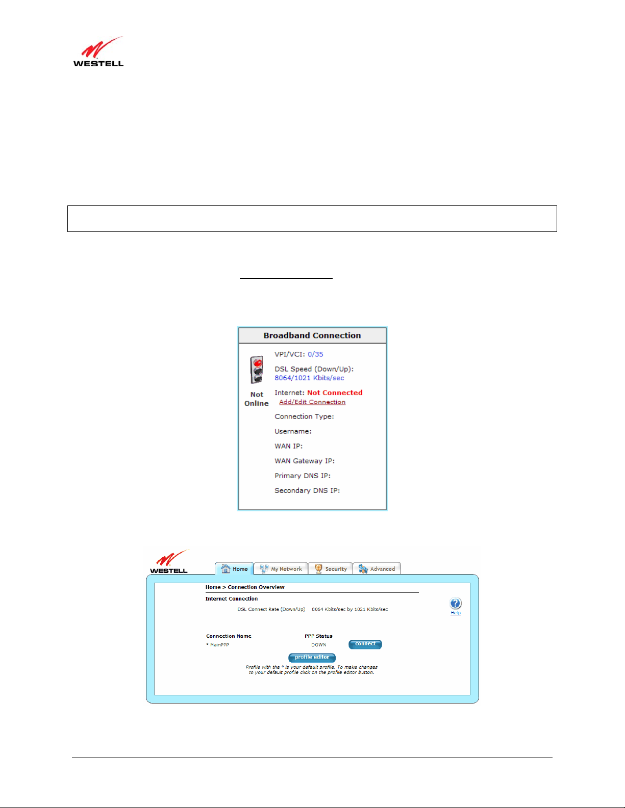
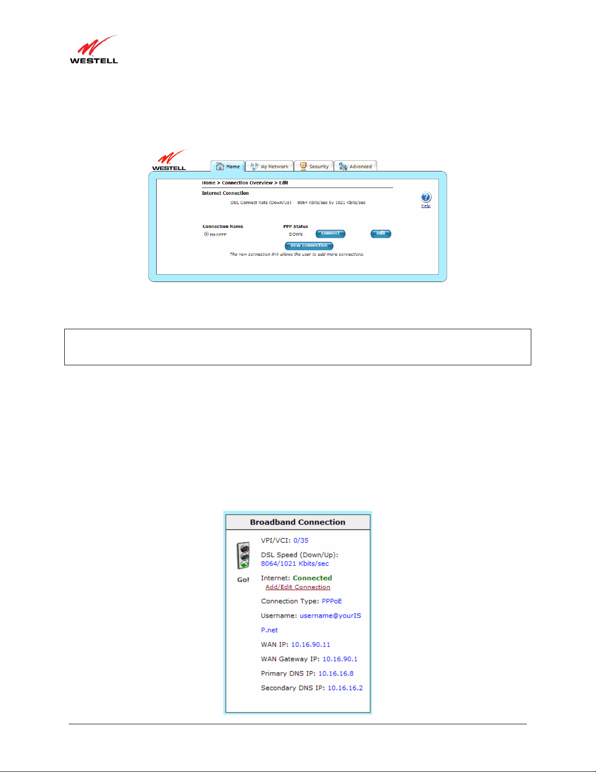
1. Go to the Home page, and click the Add/Edit Connection
Connection Overview screen. The Connection Overview screen displays the status of your Internet
connection. In the screen below, the status displays DOWN. This means that you do not have an Internet
connection.
link in the Broadband Connection to go to the
2. Click profile editor to set up your connection profile. The Edit screen (Home > Connection Overview) will
appear.
030-300564 Rev A 23 August 2009
)
User Guide ProLine G90 (Models 6100, 6110
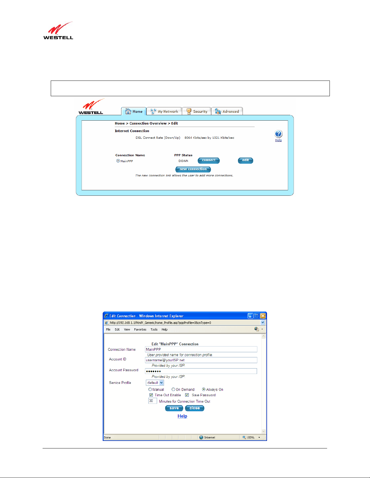
3. Click edit. The Edit Connection window will appear. This window allows you to change the connection profile
settings defined in the modem.
NOTE: To create an entirely new connection profile, rather than edit an existing one, click new connection
instead of edit.
4. Type in the following information in the fields provided and select from the following options:
• Connection Name: This is description for the connection profile that your modem will use. This name
is supplied by your ISP.
• Account ID: This is your account ID. This ID is supplied by your ISP.
• Account Password: This is your account’s password. This password is provided by your ISP.
• Service Profile: This drop-down menu lists pre-defined Service Profi le s.
• Manual/On Demand/Always On: These are options for specifying how this particular connection
profile is used.
• Time Out Enable: This check box enables/disables an automatic modem inactivity timeout.
• Save Password: This check box to enables/disables automatic password entry.
• Minutes for Connection Time Out: This is the number of minutes specified before the Time Out
Enable feature disconnects the modem from the ISP.
030-300564 Rev A 24 August 2009

)
User Guide ProLine G90 (Models 6100, 6110
Refer to the following table for detailed information on each of the Edit/New Connection window fields.
Connection Name Displays the description for the connection profile that your modem will use. This
field allows you to type in the desired name that you want to use for each profile that
you set up. You can create and store up to eight unique connection profiles in your
modem, which you can use once you establish a PPP session with your ISP. This field
allows a maximum of 64 characters. Remember, use MainPPP as the connection
name if you are connecting for the first time.
Note: When you establish a PPPoE session for the first time, you must use the factory
default Connection Name “MainPPP” to connect to your ISP. Then, if you want set
up additional profiles, you can use connection names of your choice. The Connection
Name is the name associated each connection profile.
Account ID Displays your Account ID as supplied by your ISP. The Account ID field allows a
maximum of 255 characters.
Account Password
Displays your Account Password as provided by your ISP. The Account Password is
masked for extra security. This field allows a maximum of 255 characters.
Service Profile Click this drop-down menu to select a pre-defined Service Profile. A service profile is
a collection of settings for the built-in firewall and NAT. These settings control which
applications are enabled to communicate through the modem. This selection specifies
which service profile is used with this connection.
Manual/On
Demand/Always On
Select the option to specify how this connection profile is used. By default, the
modem’s connection setting is set to Always On.
• Manual: Select this option to manually establish your PPP session.
• On Demand: Select this option to automatically reestablish your PPP session
on demand anytime your PC requests Internet activity (for example,
browsing the Internet, email, etc.). Please note that when you have Internet
traffic, this setting may cause a delay.
• Always On: Select this option to automatically establish a PPP session when
you log on or if the PPP session goes down.
Time Out Enable Click this check box to enable disconnect timeout. If enabled, the modem will
monitor the ISP connection for activity. If there is no activity for the time out period,
the modem will disconnect from the ISP.
Note: The timeout option will be dimmed if you select Always On as your
connection setting.
Save Password Click this check box to enable automatic password entry. If enabled, the modem will
automatically insert your Account Password. By default, this feature is enabled
(checked).
Minutes for Connection
Time Out
Displays the number of minutes of inactivity before your modem will disconnect
from the ISP.
5. Click save and then OK to save the connection settings.
Congratulations! You have completed setting up your PPPoE connection profile. Now, go to section 7.4,
“Confirming Your Internet Connection,” to confirm your Internet connection.
030-300564 Rev A 25 August 2009
)
User Guide ProLine G90 (Models 6100, 6110
7.4 Confirming Your Internet Connection
If you clicked the Save button in the Edit or New Connection window, the following screen will appear.
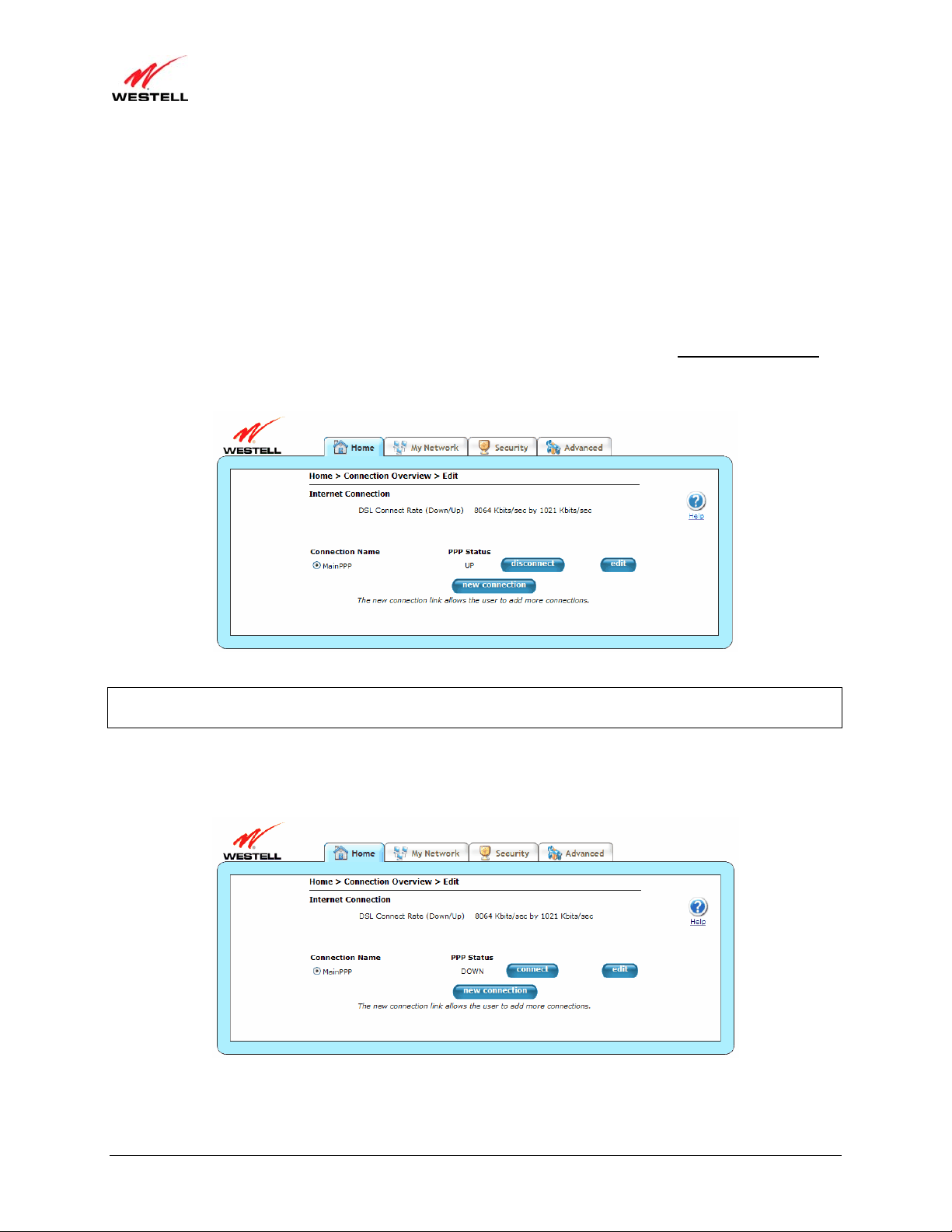
Click the Connect button, and wait a brief moment while the modem connects to the Internet. The Status field will
display UP once an Internet connection has been established.
NOTE: If your modem’s connection setting is set to Always On or On Demand, after a brief delay, the Internet
connection will be established automatically; however, if the connection setting is set to Manual, you must click the
Connect button in the Connection screen to establish an Internet connection.
Additional ways to confirm your Internet connection are:
• In the Broadband Connection panel of the Home page, vi ew the Internet field. If the status reads Not
Connected, you do not have a DSL link. However, if the Internet field displays Connected and the Speed
(Down/Up) field displays numeric values, a DSL link has been established. The values displayed represent
the transmission rates of your DSL signal (downstream and upstream). You may need to wait a brief
moment for the modem to report these values.
• At the top of the modem, check to see if the DSL LED is solid green. Solid green indicates that the
modem’s DSL connection has been established. (The DSL LED may flash wh ile the connection is being
established.) Please wait a brief moment for the modem to connect.
030-300564 Rev A 26 August 2009
)
User Guide ProLine G90 (Models 6100, 6110
If you do not have a DSL sync, first check your physical connections. (Refer to section 5, “Hardware Installations,”
if needed.) If the problem persists, contact your ISP for further instructions.
Congratulations! You have established an Internet connection. You can now Go! browse the Internet. For example, to
visit Westell’s home page, type http://www.westell.com in your Internet browser’ s address bar, and then press Enter
on your keyboard.
7.5 Disconnecting from an Internet Session
If you have finished browsing the Internet and want to disconnect from your ISP, click the Add/Edit Connection
link from the Broadband Connection panel. The following Home > Connection Overview screen will appear.
Click disconnect and then OK.
IMPORTANT: If you disconnect the PPP session, this will disconnect the modem from the Internet, and Internet
access for all users connected to the modem will be down until the PPP session is re-established.
If you clicked the disconnect button in the Home > Connection Overview screen, after a brief moment, PPP
Status should display DOWN. This means that you no longer have a PPP session. However, your DSL session will
not be affected. When you are ready to end your DSL session, simply unplug the modem from its power source.
When you are ready to establish a PPP session again, click the connect button in the Home > Connection
Overview screen. If you have previously unplugged the modem, first plug in the modem, and then log on to your
account profile to establish a PPP session.
030-300564 Rev A 27 August 2009
)
User Guide ProLine G90 (Models 6100, 6110
NOTE: When you are ready to exit the modem’s interface, click on the X (close) in the upper-right corner of the
browser window. This will not affect your PPP Status; i.e., your PPP session will not be disconnected. You must
click the disconnect button to disconnect your PPP session. To restore this interface, open your Internet browser
window, type http://192.168.1.1/ in the browser’s address bar, and then press Enter on your keyboard. Type your
User name and Password in the pop-up screen as needed.
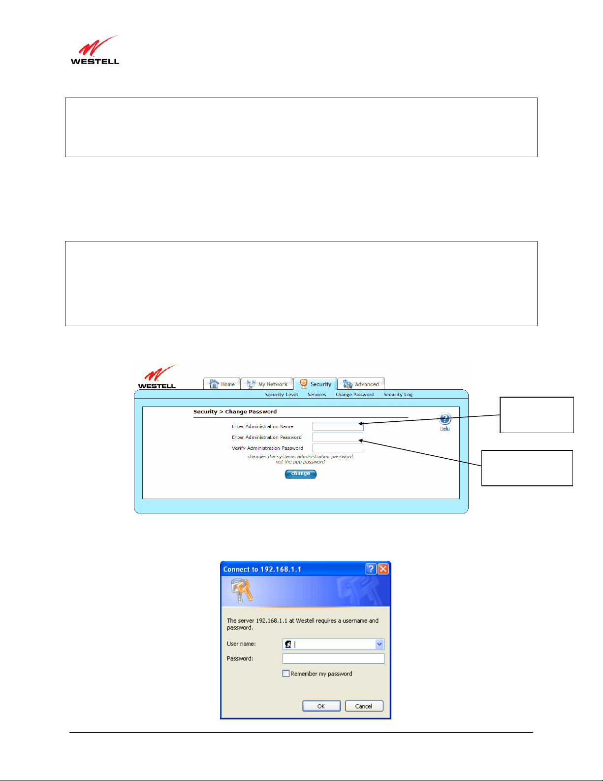
7.6 Changing the Administration Password
It is recommended that you change the administration password of your modem after completing initial installation
and setup. You can accomplish this through the Change Password screen (Security > Change Password). This
screen allows you to change the default administration name and password to values of your choice.
IMPORTANT:
1. The Security > Change Password screen allows you to use admin as your administrator name (your
administrator name can match yo ur user name). However, you may not use password as your administrator
password. The values in these fields are case sensitive. Once you decide on an administrator name and password,
please record them for future reference.
2. This feature changes the Administrator’s password, not the PPP password.
Type your Administration Name and your Administration Password in the fields provided, and then click change
and OK. The password fields will be masked for security purposes.
Type a new password.
(Do not type the word
password here.)
If you clicked OK after clicking change, the following screen will appear. Type in your new User name and
Password in the fields provided, and then click OK.
Type admin or
the name of
your choice.
030-300564 Rev A 28 August 2009
)
User Guide ProLine G90 (Models 6100, 6110
8. SETTING UP MACINTOSH OS X
This section provides instructions on how to use Macintosh Operating System 10 with the modem. Follow the
instructions in this section to create a new network configuration for Macintosh OS X.
NOTE: Macintosh computers must use the modem’s Ethernet installation. Refer to section 5, “Hardware
Installations,” for details.
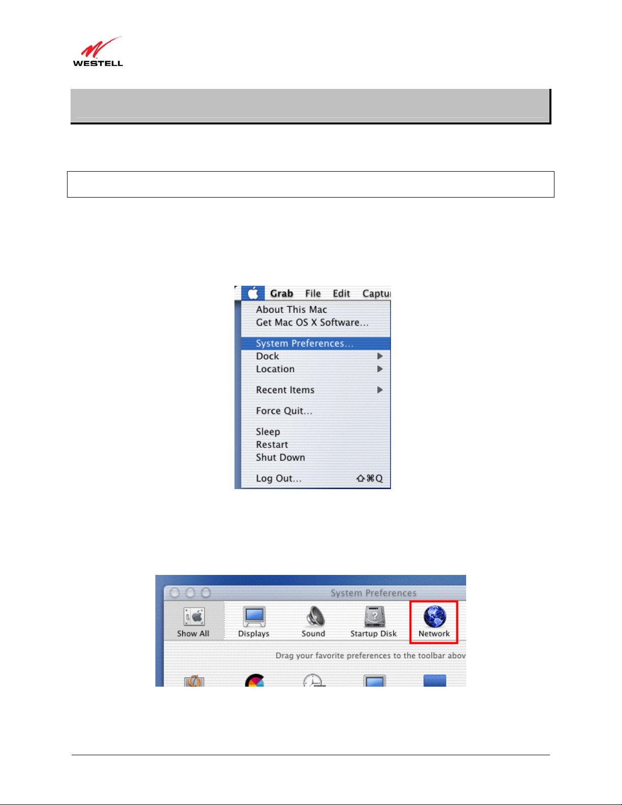
8.1 Opening the System Preference Screen
After you have connected the modem to the Ethernet port of your Macintosh, the screen below will appear. Click the
Apple icon in the upper-left corner of the screen, and select System Preferences.
8.2 Choosing the Network Preferences
After selecting System Preferences from the previous screen, the following screen will appear. Click the Network
icon.
030-300564 Rev A 29 August 2009
)
User Guide ProLine G90 (Models 6100, 6110
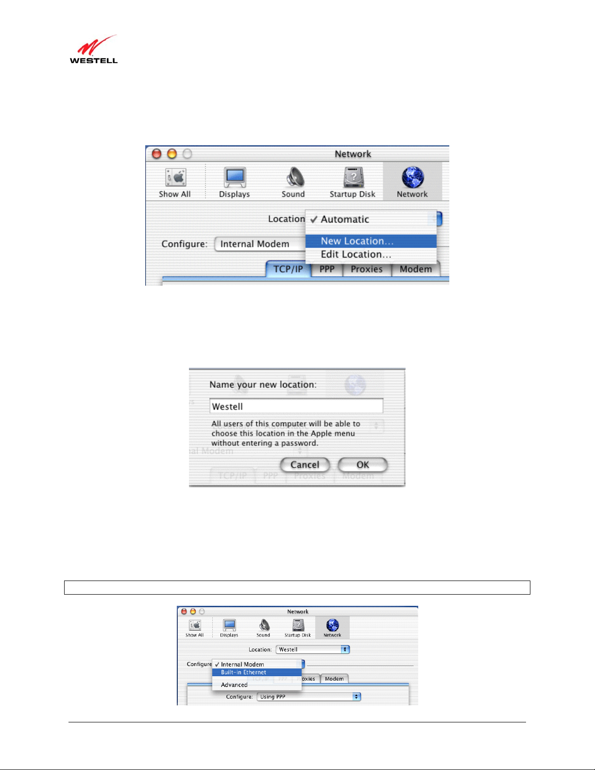
8.3 Creating a New Location
After clicking the Network icon, the following screen will appear. Select New Location from the Location field.
8.4 Naming the New Location
After selecting New Location in the Network screen, the following screen will appear. In the field labeled
Name your new location:, change the text from Untitled to Westell. Click OK.
8.5 Selecting the Ethernet Configuration
After clicking OK in the Name your new location: screen, the Network screen will appear. The Network screen
displays the settings for the newly created location. From th e Configure field in the Network screen, select Built-in
Ethernet. Click Save to save the settings.
NOTE: Default settings for the Built-in Ethernet configuration are sufficient to operate the modem.
030-300564 Rev A 30 August 2009
Loading...