

WESTEK TM104R Instruction Manual & Warranty
TM104R
Instruction Manual & Warranty
http://waterheatertimer.org/Boxtype.html#Westek
Mechanical Time Switch
DOUBLE POLE/SINGLE THROW (DPST)
40 AMP RESISTIVE, INDUCTIVE, TUNGSTEN
OR 1000VA PILOT DUTY
EACH POLE 120V-480 VAC
2HP (24FLA)-120VAC; 4HP (28FLA)-240VAC
Timer Motor Input Voltage:
208-277 VOLTS-60Hz between terminal
[A] and terminal [LINE1].
208 OR 240V
SUPPLY
LINE1
LINE2
NEUTRAL
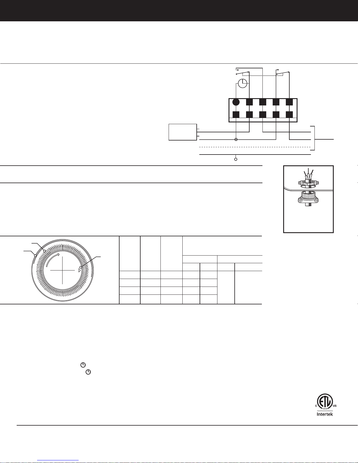
WIRING INSTRUCTIONS
208V OR 240V DPST
For 277/480 volt supply do not connect LINE2 to terminal A.
Connect supply NEUTRAL to Terminal A.
Remove terminal cover plate to get access to the terminals. Remove knockouts and insert and secure wiring
as required by local electrical codes.
To wire switch follow diagram above. Use only solid or stranded COPPER wire with insulation to suit installation.
See gauge selection table for normal service applications. To make power connections remove 1/3 inch of insulation
from wire ends. Insert bare ends of wire under the pressure plate of terminals. Use screwdriver to tighten terminal
screws firmly (25in-lb minimum).
REPLACE INSULATOR PLATE BEFORE TURNING ON ELECTRICITY
A
LINE1 LOAD1 LINE2 LOAD2
GROUND
LOAD1
LOAD2
NEUTRAL
TO LOAD
Install UL approved
cable connector
following local
electrical codes
1
1
Segment
Dial
3
4
5
6
7
8
9
0
1
1
2
2
1
11
10
9
Arrow
8
7
6
5
4
3
2
2
1
1
MINIMUM
COPPER
WIRE SIZE
(AWG)
14
12
10
8
MAX
LOAD
(AMP)
15
20
30
40
MIN
INSULATION
TEMP
(°C)
60
60
60
75
75°C INSULATION MAX. MOTOR LOAD
SINGLE PHASE 3 PHASE
120V 240V 208V 240V
1/2
1
2
2
2 1/2
3
(HP)
N/A N/A
4
PROGRAMMING INSTRUCTIONS: TO SET “ON” AND “OFF” TIMES
1. SET ON/SET OFF TIMES. Locate segment pins on the dial
2. Push segments toward the outer rim of the dial to select the ON time. Push out all segments falling within
the period of time that the power will be on. Each segment represents 15 minutes.
3. Push all segments falling within the period of time that the power will be OFF toward the
center of the dial.
4. SET TIME OF DAY. Rotate the dial in clockwise direction until the arrow points to the current time.
Rotating the dial in the counter clockwise direction will permanently damage your timer.
5. SET OFF/ON OR TIMER (
) MODE OF OPERATION
6. Place selector switch in the ( ) position to select timer operation
7. Place selector switch in ON position to turn power on. Power will not turn off until the switch is changed.
8. Place selector switch in OFF position to turn power off. Power will not turn on until switch is changed.
9. In case of power failure reset clock dial to proper time of day. (Step 4)
Questions? 201.661.9945
©2011 AmerTac™
Saddle River Executive Centre,
One Route 17 South, Saddle River, NJ 07458
www.amertac.com
Made in China
3182003
Limited One Year Warranty: AmerTac™ warrants this product to be free from defects in material and workmanship for a period
of one year from the date of purchase. AmerTac’s obligations are limited to repairing or replacing any defective unit and are effective
only if such units are returned within one year of the purchase date to AmerTac, 250 Boulder Drive, Breinigsville, PA 18031. Warranty
void if damage is due to misuse or improper installation. In no circumstance will AmerTac be liable for consequential or incidental
damages relating in any way to this product.

TM104R
Manual de instrucciones y garantía
Interruptor horario mecánico
DOBLE POLO/UNA VÍA (DPST)
40 AMP RESISTIVOS, INDUCTIVOS, TUNGSTENO
O SERVICIO PILOTO DE 1000VA
CADA POLO 120V-480 VCA
2HP (24FLA)-120VCA; 4HP (28FLA)-240VCA
Voltaje de entrada del motor del temporizador:
208-277 VOLTIOS-60Hz entre la terminal [A]
y la terminal [LÍNEA1].
SUMINISTRO DE
208 ó 240V
LÍNEA1
LÍNEA2
NEUTRAL
A
INSTRUCCIONES DE CABLEADO
208 V
Para el suministro de 277/480 voltios, no conecte LÍNEA2 a la terminal A.
Conecte el suministro NEUTRO a la terminal A.
Retire la placa de cubierta de terminal para lograr acceso a las terminales. Retire los destapaderos, e inserte y
asegure el cableado según lo estipulan los códigos eléctricos locales.
Para cablear el interruptor, observe el diagrama anterior. Utilice únicamente conductores sólidos o retorcidos de
COBRE con aislamiento según lo requiere la instalación. Consulte la tabla de selección de calibres para aplicaciones
de servicio normal. Para llevar a cabo las conexiones de alimentación, retire 8 mm de aislamiento de los extremos
de los conductores. Inserte los extremos desnudos del conductor debajo de la placa de presión de las terminales.
Utilice un destornillador para apretar los tornillos terminales (2.8 Nm mínimo).
REEMPLACE LA PLACA DE AISLAMIENTO ANTES DE CONECTAR LA ELECTRICIDAD
ó 240 V DPST
LÍNEA1
TIERRA
CARGA1
LÍNEA2
CARGA2
CARGA1
CARGA2
NEUTRAL
Instale un conector para
cable aprobado por UL
observando los códigos
eléctricos locales.
A LA
CARGA
Segmento
Cuadrante
1
1
2
2
3
4
5
6
7
8
9
0
1
1
1
1
1
10
9
8
7
6
5
4
3
2
2
1
1
Flecha
TAMAÑO
MÍNIMO DEL
CONDUCTOR
DE COBRE
(AWG)
14
12
10
CARGA
MÁX
(AMP)
15
20
30
8
40
TEMP
MÍN DE
AISLAMIENTO
(ºC)
60
60
60
75
AISLAMIENTO MÁX. 75ºC
CARGA DEL MOTOR (HP)
UNIFÁSICO TRIFÁSICO
120V 240V 208V 240V
1/2
1
2
2
2 1/2
3
N/A N/A
4
INSTRUCCIONES DE PROGRAMACIÓN: PARA ESTABLECER LAS HORAS DE “ENCENDIDO” Y “APAGADO”
1. HORAS DE ENCENDIDO/APAGADO Ubique las clavijas de segmentos en el cuadrante.
2. Empuje los segmentos hacia el borde exterior del cuadrante para seleccionar la hora de Encendido. Empuje
hacia fuera todos los segmentos ubicados dentro del período de tiempo que la alimentación estará encendida.
Cada segmento representa 15 minutos.
3. Empuje todos los segmentos ubicados dentro del período de tiempo que la alimentación estará apagada
hacia el centro del cuadrante.
4. HORA DEL DÍA. Gire el cuadrante hacia la derecha hasta que la flecha apunte hacia la hora actual.
Girar el cuadrante hacia la izquierda ocasionará daños permanentes al temporizador.
5. MODO DE FUNCIONAMIENTO (
6. Coloque el interruptor selector en la posición (
) DE ENCENDIDO/APAGADO O TEMPORIZADOR
) para seleccionar la operación del temporizador.
7. Coloque el interruptor selector en la posición ON para encender la alimentación. La alimentación no
se apagará hasta que se cambie el interruptor.
8. Coloque el interruptor selector en la posición OFF para apagar la alimentación. La alimentación no
se encenderá hasta que se cambie el interruptor.
9. En caso de un fallo de alimentación, restablezca el cuadrante del reloj a la hora correcta del día. (Paso 4).
3182003
¿Preguntas? 201.661.9945
©2011 AmerTac™
Saddle River Executive Centre,
One Route 17 South, Saddle River, NJ 07458
www.amertac.com
Hecho en China
Garantía limitada de un año: AmerTac™ garantiza que este producto está libre de defectos de material y mano de obra por un
período de un año a partir de la fecha de compra. Las obligaciones de AmerTac se limitan a reparar o cambiar la unidad defectuosa
y son efectivas sólo si se devuelve en un lapso de un año a partir de la fecha de compra a AmerTac, 250 Boulder Drive, Breinigsville,
PA 18031. La garantía no será válida si el daño es causado por mal uso o instalación inadecuada. En ningún caso AmerTac será
responsable por daños consecuentes o incidentales relacionados en cualquier forma con este producto.
 Loading...