

TECHNICAL
PUBLICATION
~
WESTCODE
SEMICONDUCTORS
Flat
-Base
400
RATINGS Maximum values
Average forward current
RMS
current
DC
forward current
Peak one-cycle
Maximum permissible surge energy
Case operating temperature
Storage temperature
amperes average:
RATING
surge (non repetitive)
Silicon
at
190°C
Half sine wave
10 d . { 60% V R RM re-applied
10 d . . {
Rectifier
Diodes
up
Tj
unless stated otherwise
CONDITIONS
120°C case temperature
ms uratlon V ~ 10
ms uratlon V ~ 10
3ms duration
R volts
60%
V RRM re-applied
R volts
V
.;;;;
R
~
D
H400
ISSUE 1
May,
1980
Type
to
10 volts 245000A2s
HHN/HHR400
1500vo/ts V
SYMBOL
'FIAV)
'FIRMS)
IF
'FSMI1I
'FSM(2)
,2t
(1)
,2t
(2)
Tc
T
stg
RRM
-30,+190°C
-40,
400A
630A
630A
7500A
8250A
281000A2s
340000A%s
+200°C
CHARACTERISTICS Maximum values
CHARACTERISTIC
Peak forward voltage
Forward conduction threshold voltage
Forward conduction slope resistance
Peak reverse current
Thermal resistance junction
a diode with a maximum forward volt-
drop
characteristic
Thermal resistance case
VOLTAGE CODE
Repetitive voltage
Non-repetitive voltage V
drop
to
V
to
heatsink
....
RRM
RSM
case for
02
200
300
ORDERING INFORMATION (Please
S
BASIC CODE
FIXED
W
• •
VOLTAGE CODE
(see
above)
at
190°C
At
1500A,
At V
DC
and 180° sine wave
120°
400
500 700
quote
IFM
RRM
rectangular wave
04
device code as explained below - 10 digits)
H
OUTLINE CODE
Tj
unless stated otherwise
CONDITIONS
06
600 800
FIXED
H
08
900
1000 1200
1100
POLARITY
N • c:atttode
10
BASE
R·
•
anode
SYMBOL
V
FM
Vo
r
IRRM
R
-
c)
thli
Rth(c_ hs)
12 14
1300
1400
1500
4
1.62V
0.8V
0.55mn
15mA
0.13°CIW
0.14°CIW
O.04°CIW
15
1500
1600
0 0
FIXED
TVPECODE
Typical code SW06HHR400 = 600V
In
the
intrllftt
of
product
improVtlmtlnt. Westrode rest6fVfIS the
diode with base anode
RRM
right
to
changtl6fJllCifiations
at
any
time
without
notice.
o
H400
U
°
:!i
.~
~
;0
0;'
.S'
;0
!?:
~
-0
~
'"
~
E
)(
'"
E
C.
E
~
e:
u
'"
"
E
0.
'"
x
'"
E
~
190
r...~
170
150
130
110
90
a
800
700
600
500
400
300
200
100
a
a
i'~~
i'
0['-.
i\
6
phase
100
200
6
phase
V
~
~
100
200
mean
forward
current.
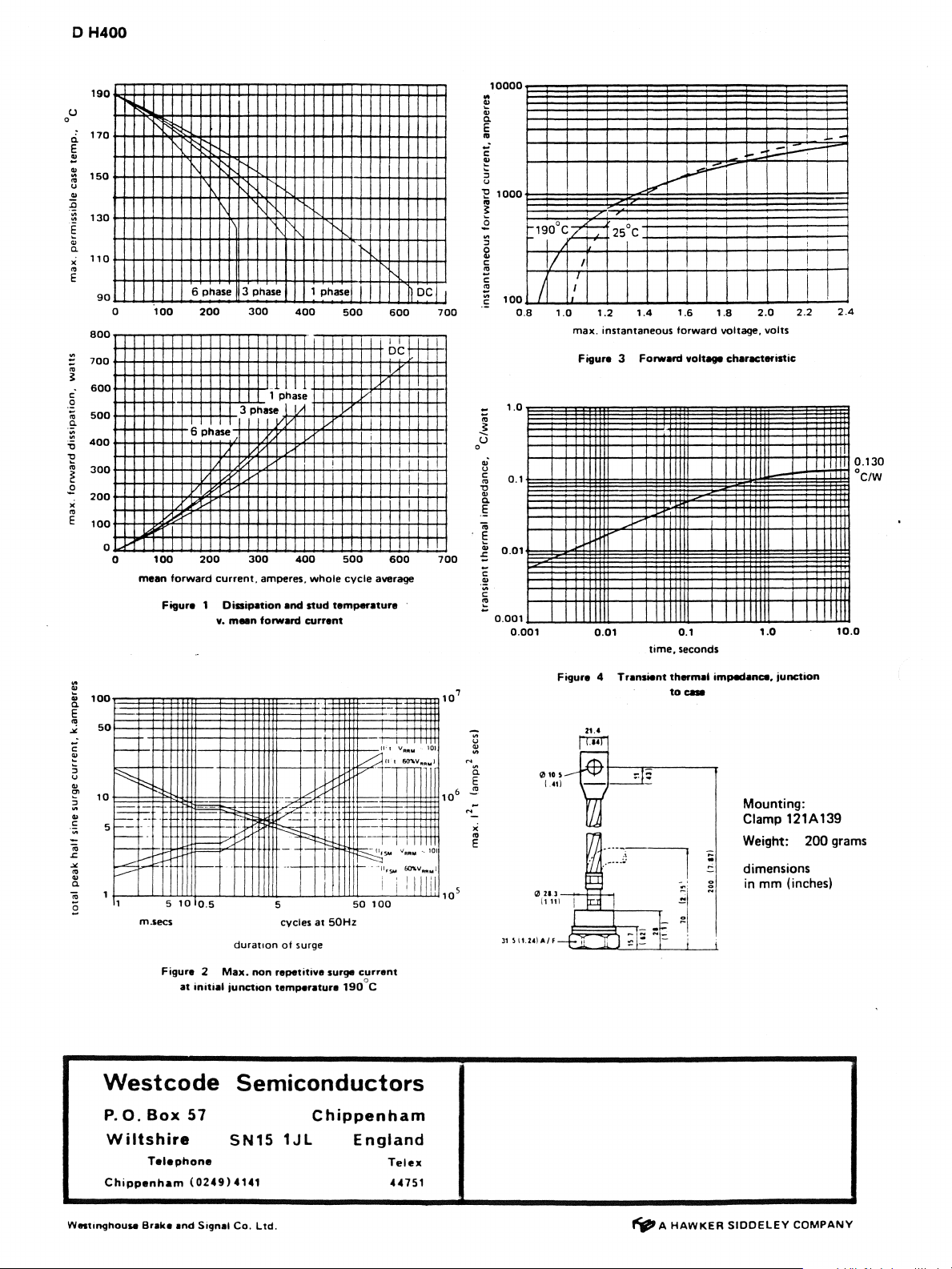
Figura 1 Dissipation
v.
"-
'\
3 phase 1
300
1 phase
3
phase
V
300
amperes.
maan
forward
and
400
400
whole
stud
currant
phase
500
I
I
I
500
cycle
temperature
600
ot
,
600
average
DC
H+
I
I
I
700
I
I
I
700
10000
..
~
0.
'"
E
..
E
~
:::l
u
'E
1000
:,.r"
,
I
I
rt:
PI
;...:::.
I
,
I
..:::.-:---
I
I
-
~
.2
5
g
c:
e
c:
~
I
.=
;;;
!:
U
°
<II'
U
c:
-0
'"
<II
0.
E
;;;
§
<II
.:;
C
.!!
C
~
100
1.0
0.1
0.01
0.001
190°C/+
il
/
0.8
0.001
_
25°C
I
I I
I
I
1.0
1.2
max.
instantaneous
Figura
3
I-""
0.01
1.4
Forward
time,
I
I
1.6
forward
voltage charllCteristic
0.1
seconds
1.8
voltage,
2.0
volts
1.0
2.2
,
I
I
,
2.4
0.130
°C/W
1
I
10.0
~
100
0.
"
E
"!
50
.><
-'
C
~
:;
U
~
<II
10
'"
~
<II
r=-
0;
1-.
5
f--
;;;
~
<II
'"
<II
~
0.
;;;
1 5
8
Westcode
P.
O.
Wiltshire
Chippanham
P::
f-
-1
r::
m.secs
Figure 2
Box
Talaphone
10
at
57
(0249)
- .
.
~:?~
--
duration
oon
~~~
tf
I
I : I
5
at
cycles
ot
surge
repetitive surge
temperatura
f--
f---
as
initial
Max.
junction
Semiconductors
Chippenham
SN15
4141
1JL
\-
t
I
50Hz
1900 C
-
.t-H-!itt
_.
,
II I V
Rlltoil
~~.
50W".'
I
1--';"'-
1--
--r-
,-t
~~o;,.
"AI'IM'
r--
.
·11~SlI;
6O't.v
i
:
i
1
50
00
curr8nl
England
Telex
44751
101
'0,
Im",i
Illil
107
x
..
E
Figura 4
21.'
Transient
thermal
to_
impedance.
junction
Mounting:
Clamp
121A
Weight: 200 grams
dimensions
in
mm
(inchesl
139
W.,.t'09housa
Braka
and
Signal
Co.
Ltd.
~
A
HAWKER
SIOOELEY
COMPANY
 Loading...