

Page 1
1 or 2 control loops
ON/OFF, PID heat only & Heat/Cool, Valve Motor Drive, Ratio Cascade Control
255 segment profiler shared in 64 programs
5 PID sets manual or automatic gain scheduling
7 Alarms – absolute, deviation, rate of change, sensor break, recorder memory,
power
Datalogging function
USB host for configuration (read/write) and logged data (read)
Ethernet – Modbus TCP, RS485 - Modbus RTU (Master/Slave)
Up to to 2 analogue inputs, 9 outputs, remote setpoint input, 9 digital inputs
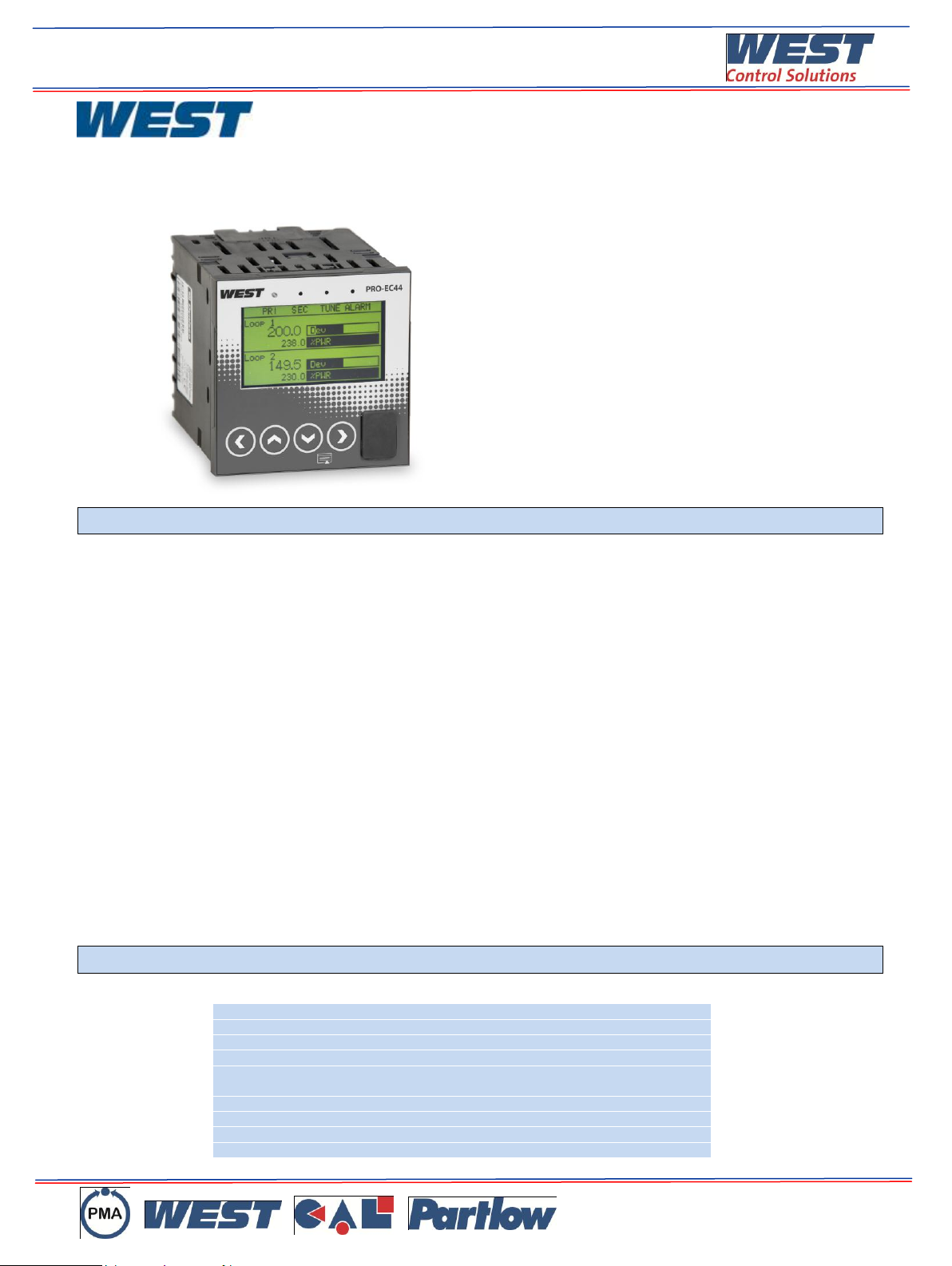
PRO-EC44 Single or two loop advanced
controller with graphic display
KEY FEATURES
1/4 DIN Format
Single or Two Loop
Graphical / text LCD Display (red/green)
USB configuration and data access
Profiler 256 segments shared in 64 progs
Datalogger with real time clock
Modbus RS485 or Modbus TCP Ethernet
Standards CE, UL
Overview
Pro-EC44 is a 1/4 DIN process controller with graphical text display, advanced control capability and modular I/O options providing flexibility to
fit wide range of industrial manufacturing and process applications.
Fast and easy front panel setup for both for simple and advanced control tasks
Pro-EC44 simplifies user setup with a step by step wizard configuration saving working through several menus for initial setup. A Logical
menu structure for intuitive navigation allows fast changes and updates to individual settings.
Configure controllers without connecting to a PC
Configuration files can be downloaded to a controller using a flash memory stick via the front USB port allowing for fast programming. Settings
can also be read via the USB port to clone additional devices or configure a replacement. Datalog files can also be extracted locally via the
USB for convenient access of process data.
Easy access user operation
The Pro-EC44 pages are formatted to show users important process information on a single page, minimising the steps to access data and
settings. A colour change green/red LED backlight provides easily recognisable alarm indication to improve response times for corrective
action.
Comprehensive control ….. and much more.
Pro-EC44 includes many features to ensure good control performance on a wide range of applications.
Single or dual loop capability in a single device, cascade, valve and ratio enhanced control with support features such as real time clock, timer,
gain scheduling and profiler ensure Pro-EC44 has the flexibility for a process system needs. In addition datalogging, trending, USB, Ethernet
options add even more capability to an already powerful device.
Fast configuration via configuration interface.
Direct access for programming is available via a top of controller connection port. The interface provides easy and fast access with Blue
Control software to configure the controller or drilldown into process issues with minimal disruption.
Key Features
Ref DS-EC44-01013-2-EN
© West Control Solutions 2013
Page 2
Specification
UNIVERSAL INPUT 1 AND 2
Sampling Rate:
10 per second.
Resolution:
16 bits. Always four times better than display resolution.
Impedance:
>10M resistive, except DC mA (5) and V (47k ).
Temp Stability:
Error <0.01% of span per °C change in ambient temperature.
Supply Variation:
Supply voltage influence negligible within supply limits.
Humidity Influence:
Negligible if non-condensing.
Process Display:
Displays up to 5% over and 5% under span limits.
Process Variable Input
Offset:
Reading adjustable ± Controller Span. +ve values added to Process Variable, -ve values subtracted from Process
Variable
Sensor Break Detection:
Thermocouple & RTD - Control goes to pre-set power value. High & Sensor Break alarms activate.
Linear (4 to 20mA, 2 to 10V & 1 to 5V only) - Control goes to pre-set power value. Low & Sensor Break alarms
activate.
Isolation:
Reinforced safety isolation from outputs and other inputs
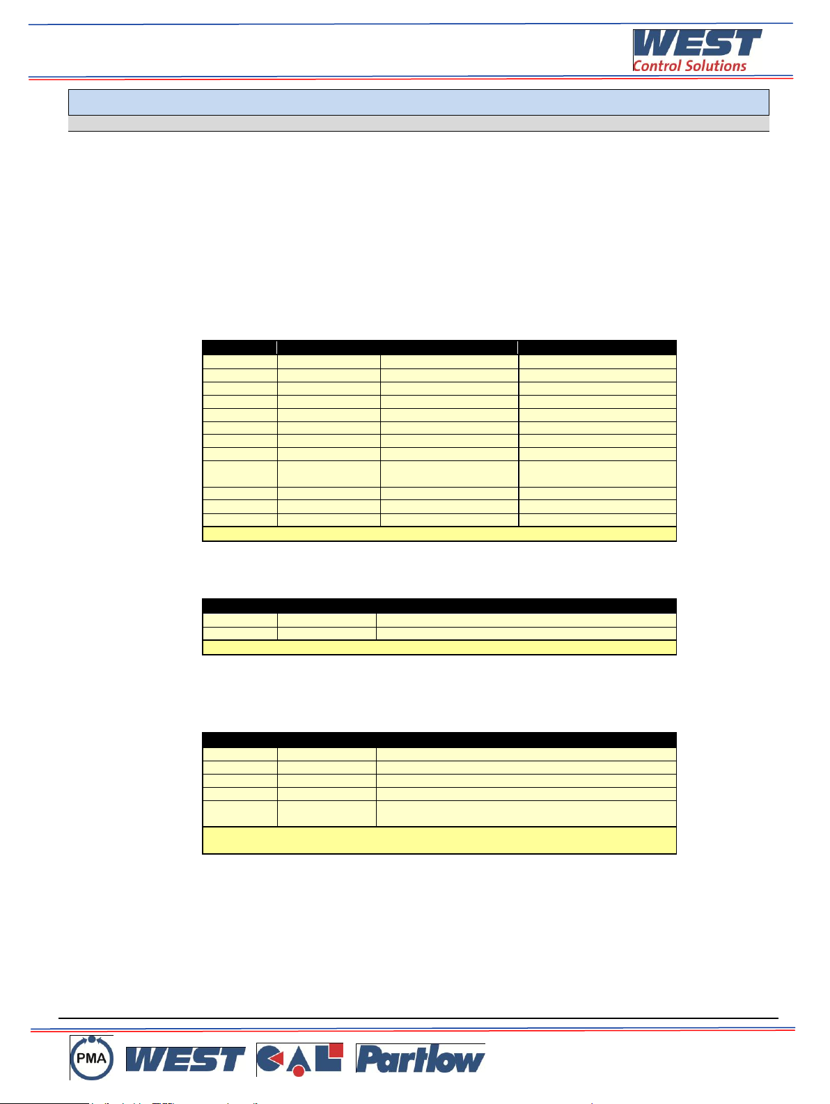
Supported Thermocouple
Types & Ranges:
Type
Range °C
Range °F
B
+100 to 1824°C
+211 to 3315°F
C
0 to 2320°C
32 to 4208°F
D
0 to 2315°C
32 to 4199°F
E
-240 to 1000°C
-400 to 1832°F
J
-200 to 1200°C
-328 to 2192°F
*
K
-240 to 1373°C
-400 to 2503°F
*
L
0 to 762°C
32 to 1402°F
*
N
0 to 1399°C
32 to 2551°F
*
PtRh
20%:40%
0 to 1850°C
32 to 3362°F
R
0 to 1759°C
32 to 3198°F
S
0 to 1762°C
32 to 3204°F
T
-240 to 400°C
-400 to 752°F
*
Optional decimal place can be displayed on all ranges
Thermocouple Calibration:
0.1% of full range, 1LSD (1°C for internal CJC if enabled).
Linearization better than better 0.2C (0.05 typical) on ranges marked * in the table above.
Linearization for other ranges is better than better than 0.5C.
BS4937, NBS125 & IEC584
Supported RTD Types &
Ranges:
Type
Range °C
Range °F
3-Wire PT100
-199 to 800°C
-328 to 1472°F
NI120
-80 to 240°C
-112 to 464°F
Optional decimal place can be displayed on all ranges
RTD Calibration:
0.1% of full range, 1LSD.
Linearization better than 0.2C (0.05 typical).
PT100 input to BS1904 & DIN43760 (0.00385//°C).
RTD Excitation:
Sensor current 150μA 10%.
Lead Resistance:
<0.5% of span error for max 50per lead, balanced.
Supported Linear Types &
Ranges:
Type
Range
Offset Range
mA DC
0 to 20mA DC
4 to 20mA DC
mV DC
0 to 50mV DC
10 to 50mV DC
V DC
0 to 5V DC
1 to 5V DC
V DC
0 to 10V DC
2 to 10V DC
Potentiometer
≥100 ohms
N/A
Scalable from -2000 to 100000. Decimal point selectable from0 to 3 places, but rounds to 2
places above 99.999; 1 place above 999.99 and no decimal above 9999.9.
Maximum Overload:
1A on mA input terminals, 30V on voltage input terminals.
DC Calibration:
0.1% of full range, 1LSD.
DC Input Multi-Point
Linearization:
Up to 15 scaling values can be defined anywhere between 0.1 and 100% of input.
Ref DS-EC44-01013-2-EN
© West Control Solutions 2013
Page 3
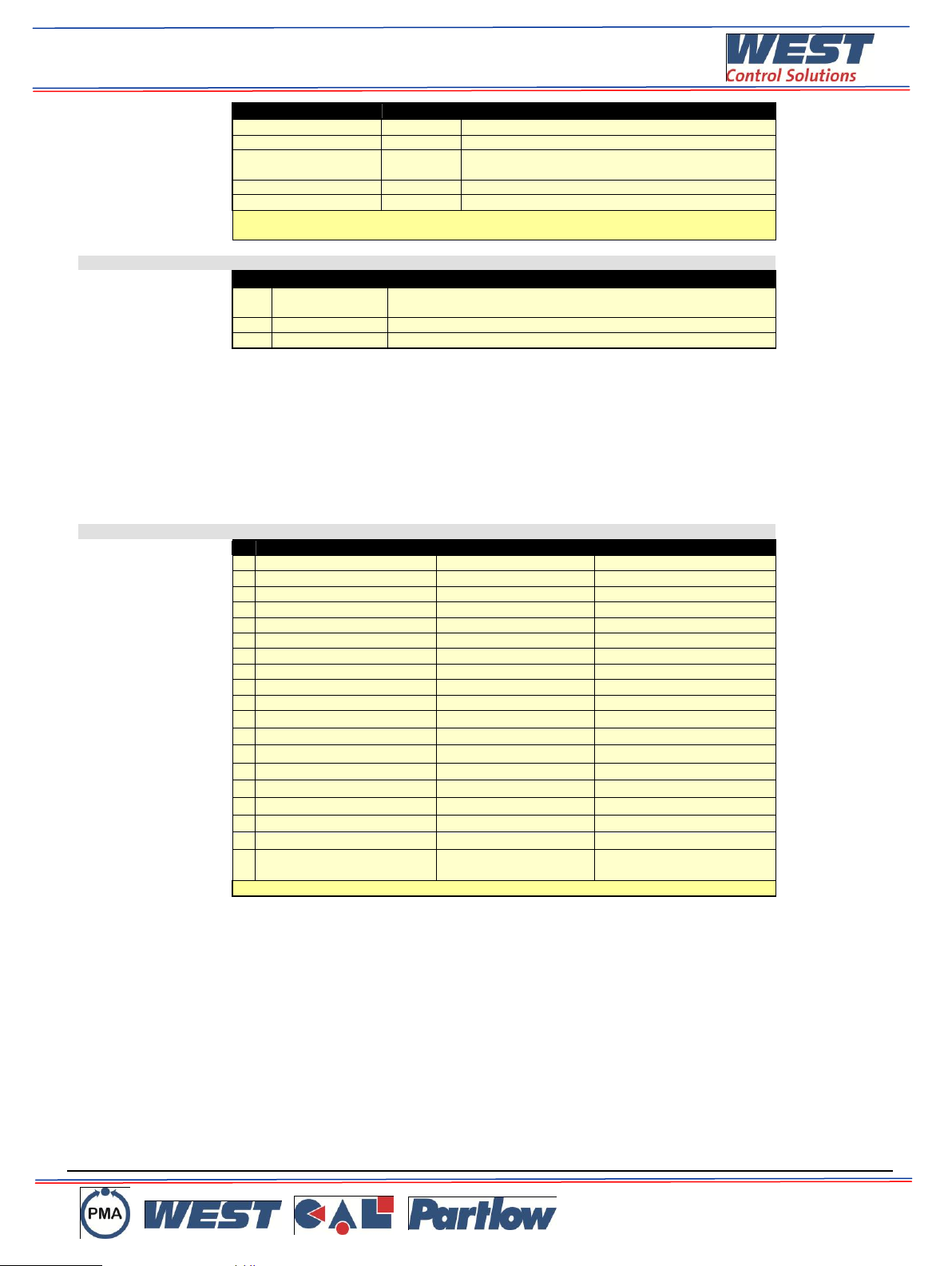
Input Functions:
Function
Input 1
Input 2
Process Control
Loop 1
Loop 2
Cascade Control
Slave Loop
Master Loop
Ratio Control
Controlled
Variable
Un-controlled Variable
Remote Setpoint (RSP)
-
RSP on loop 1
Valve Position Feedback
-
Valve on loop 1
RSP Linear inputs only, scalable between -9999 to 10000, but actual setpoint value is kept
within the setpoint limit settings
#AUXILIARY INPUT A
Supported Input Types &
Ranges:
Type
Range
Offset Range
MA
DC
0 to 20mA DC
4 to 20mA DC
V DC
0 to 5V DC
1 to 5V DC
V DC
0 to 10V DC
2 to 10V DC
Accuracy:
0.25% of input range 1 LSD.
Sampling Rate:
4 per second.
Resolution:
16 bits.
Impedance:
>10M resistive, except DC mA (10) and V (47k ).
Sensor Break Detection:
4 to 20mA, 2 to 10V and 1 to 5V ranges only. Control goes to pre-set power value if Aux Input is
the active setpoint source.
Isolation:
Reinforced safety isolation from outputs and inputs.
Input Function:
Remote Setpoint (RSP) input, Scalable between ±0.001 & ±10000, but always constrained by
the setpoint limit settings.
DIGITAL INPUTS A & C
Selectable Digital Input
Functions:
Function
Logic High*
Logic Low*
┌ ┐
Loop 1 Control Select
Enabled
Disabled
┌ ┐
Loop 2 Control Select
Enabled
Disabled
┌ ┐
Loop 1 Auto/Manual Select
Automatic
Manual
┌ ┐
Loop 2 Auto/Manual Select
Automatic
Manual
┌ ┐
Loop 1 Setpoint Select
Main SP
Alternate SP
┌ ┐
Loop 2 Setpoint Select
Main SP
Alternate SP
┌ ┐
Loop 1 Pre-Tune Select
Stop
Run
┌ ┐
Loop 2 Pre-Tune Select
Stop
Run
┌ ┐
Loop 1 Self-Tune Select
Stop
Run
┌ ┐
Loop 2 Self-Tune Select
Stop
Run
█
Profile Run/Hold
Hold
Run
█
Profile Hold Segment Release
Release
No Action
█
Profile Abort
Abort
No Action
█
Data Recorder Trigger
Not Active
Active
█
Output n Forcing Open/Close
Open
Closed
█
Clear All Latched Outputs
No Action
Reset
█
Output n Clear Latch
No Action
Reset
█
Key n Mimic (for L D U R)
No Action
Key Pressed
█
Inputs C1-C7 can be used as
Binary or BCD Profile Selection
Binary 0
Binary 1
*The High/Low function can be switched using Inputs to Invert.
Digital Input Sensitivity:
Inputs work in parallel with equivalent menus, either can change function status. Response
<0.25 second.
█ = Level Sensitive: High or low sets status.
┌ ┐ = Edge Sensitive: High-Low or Low-High transition changes function. Pre-Tune always off
at power on (except auto pre-tune), but others retain their power off status at power on.
Std. Logic State:
Volt-free (or TTL):
Open contacts (>5000or 2 to 24VDC signal = Logic High
Closed contacts (<50 or -0.6 to +0.8VDC signal = Logic Low.
Inverted Logic:
Open contact (>5000
or 2 to 24VDC signal = Logic Low
Closed contact (<50 or -0.6 to +0.8VDC signal = Logic High.
Number Available
0 to 9. One from Module Slot A, 8 from Multi-Digital Input C
Isolation:
Reinforced safety isolation from inputs and outputs.
Ref DS-EC44-01013-2-EN
© West Control Solutions 2013
Page 4

OUTPUTS
Caution: Plastic pegs prevent fitting of older non-reinforced single relay modules –Remove the peg to fit dual relays (all
dual relay modules have reinforced isolation)
Single Relay 1-3
Type:
1 x Single pole double throw (SPDT). Plug-in Modules 1, 2 & 3.
Rating:
2A resistive at 120/240VAC with >500,000 and which contacts operations at full rated AC
voltage/current. De-rate for DC loads.
Isolation:
Reinforced safety isolation from inputs and other outputs.
Dual Relay 2-3
Type:
2 x Single pole single throw (SPST*). Plug-in Modules 2 & 3.
Rating:
2A resistive at 120/240VAC with >200,000 and which contacts operations at full rated AC
voltage/current. De-rate for DC loads.
*Dual relay modules have shared common terminal.
Isolation:
Reinforced safety isolation from inputs and other outputs.
Base Relay 4-5
Type:
1 x single pole single throw (SPST). Base outputs 4 & 5.
Rating:
2A resistive at 120/240VAC with >200,000 operations and which contacts at full rated
voltage/current. De-rate for DC loads.
Isolation:
Reinforced safety isolation from inputs and other outputs.
SSR Driver 1-3
Type:
1 x Logic / SSR Driver output. Plug-in Modules 1, 2 & 3.
Drive Capability:
Driver voltage >10V into 500 minimum.
Isolation:
Isolated from all inputs/output except other SSR driver outputs.
2x SSR Driver 2-3
Type:
2 x Logic / SSR Driver outputs*. Plug-in Modules 2 & 3.
Drive Capability:
Driver voltage >10V into 500 minimum.
*Dual SSR Driver modules have shared positive terminal.
Isolation:
Isolated from all inputs/output except other SSR driver outputs.
Triac 1-3
Type:
1 x Triac output. Plug-in Modules 1, 2 & 3.
Operating Voltage:
20 to 280Vrms (47 to 63Hz)
Current Rating:
0.01 to 1A (full cycle rms on-state @ 25°C);
de-rates linearly above 40°C to 0.5A @ 80°C.
Isolation:
Reinforced safety isolation from inputs and other outputs.
Linear DC 1, 6-7
Type:
1 x Analogue DC output. Plug-in Module 1 & Base outputs 6 & 7.
Ranges
0 to 5, 0 to 10, 2 to 10V & 0 to 20, 4 to 20mA (selectable) with 2% over/under-drive when used
for control outputs, or 0-10V adjustable Transmitter PSU.
Resolution:
8 bits in 250mS (10 bits in 1s typical, >10 bits in >1s typical).
Accuracy:
0.25% of range, (mA @ 250, V @ 2k). Degrades linearly to ±0.5% for increasing burden (to
specification limits).
Isolation:
Reinforced safety isolation from inputs and other outputs.
Transmit PSU 2-3
Type:
1 x DC Excitation output. Plug-in Modules 2 & 3. Caution: Only one Transmit PSU is supported.
Do not fit in both positions.
Power Rating:
24V nominal (19 to 28V DC) into 910 minimum resistance. (Option to use DC Linear output as
0-10V stabilised PSU).
Isolation:
Reinforced safety isolation from inputs and other outputs.
COMMUNICATIONS
PC Configuration
Functions
PC software configuration, data extraction and profile creation.
Connection:
RS232 via PC Configurator Cable to RJ11 socket under case.
Isolation:
Not isolated from input or SSR Driver outputs. For bench configuration only. CAUTION: Do not
use in live applications.
RS485
Functions
Setpoint broadcast master or general communications slave (inc. extraction of data recordings,
transfer of configuration & profile files to/from PC software).
Connection:
Plug-in Module Slot A. Connection to rear terminals 16-18.
Protocol:
Modbus RTU.
Address Range
Slave address 1-255 or Setpoint master broadcast mode.
Supported Speeds:
4800, 9600, 19200, 38400, 57600 or 115200 bps.
Data Type:
10 or 11 (1 start & 1 stop bit, 8 data bits plus 1 optional parity bit).
Isolation:
240V reinforced safety isolation from all inputs and outputs.
Ref DS-EC44-01013-2-EN
© West Control Solutions 2013
Page 5

Ethernet
Functions
General communications (inc. extraction of data recordings, transfer of configuration & profile
files to/from PC software).
Connection:
Locates in Module Slot A. Connection via RJ45 connector on top of case.
Protocol:
Modbus TCP. Slave only.
Supported Speed:
10BaseT or 100BaseT (automatically detected).
Isolation:
240V reinforced safety isolation from the supply, inputs and outputs.
USB
Functions
Extraction of data recordings, transfer of configuration & profiles files to/from PC software or
direct to another controller.
Connection:
Connection via optional front mounted connector.
Protocol:
USB 1.1 or 2.0 compatible. Mass Storage Class.
Supply Current:
Up to 250mA.
Targeted Peripheral:
USB Memory Stick.
Isolation:
Reinforced safety isolation from all inputs and outputs.
LOOP CONTROL
Control types
1 or 2 control loops, each with either standard PID (single or dual control) or Valve Motor
Drive (3-point stepping PID control).
2 internally linked cascade loops, with standard PID (single or dual control) or Valve Motor
Drive (3-point stepping PID control).
1 Ratio loop for combustion control.
VMD Feedback
Second input can provide valve position feedback or flow indication. Feedback not required or
used for control algorithm.
Tuning Types:
Pre-tune, Auto Pre-tune, Self-tune or manual tuning with up to 5 PID sets stored internally.
Gain Scheduling
Automatically switch in the 5 PID sets at user definable break-points relating to PV or SP value.
Proportional Bands:
Single (Primary) or Dual (Primary & Secondary - e.g. Heat & Cool) 1 to 9999 units or On-Off
control.
Automatic Reset:
Integral Time Constant, 1s to 99min 59s or OFF
Rate:
Derivative Time Constant, 1s to 99 min 59s or OFF
Manual Reset:
Bias 0 to 100% (-100% to +100% with Dual control).
Deadband/
Overlap:
Overlap (+ve values) or Deadband (-ve values) between Primary & Secondary Proportional
Bands for Dual Control. Adjustable In display units - limited to 20% of the combined primary &
secondary proportional band width.
Differential:
ON-OFF switching differential 1 to 300 units
Auto/Manual Control:
Selectable with “bumpless” transfer when switching between Automatic and Manual control.
Cycle Times:
Selectable from 0.5s to 512s.
Setpoint Ramp:
Ramp rate selectable 1 to 9999 LSDs per hour or Off (infinite).
ALARMS
Alarm Types:
7 alarms can be assigned as Process High; Process Low; PV-SP Deviation; Band; Control
Loop; Rate Of Signal Change per minute – all with adjustable minimum duration* before
activation and optional start-up inhibit function.
Input Signal Break; % Recorder Memory Used, Control Power High, Control Power Low or
Unused.
*CAUTION: If the duration is less than this time, the alarm will not activate no matter what the
value is.
Alarm Hysteresis:
Adjustable deadband from 1 LSD to full span (in display units) for Process, Band or Deviation
Alarms.
Combination Alarm &
Events Outputs:
Logically AND or OR any alarm or profile event (inc Profile running or ended) to switch an
output. This can be when the condition is true, or the condition is not true.
DATA RECORDER
Recording Memory:
1Mb non-volatile flash memory. Data retained when power is turned off.
Recording Interval:
1; 2; 5; 10; 15; 30 seconds or 1; 2; 5; 10; 15; 30 minutes.
Recording Capacity:
Dependant on sample rate and number of values recorded.
Example: Two values will record for 21 days at 30s intervals. More values or faster sample
rates reduce the duration.
RTC Battery Type:
VARTA CR 1616 3V Lithium.
Clock runs for >1 year without power.
RTC accuracy
Real Time Clock error <1second per day.
PROFILER
A Profiler Enable Key can be purchased from your supplier if the feature is disabled.
Profile Capacity
Max 255 segments, shared by max 64 profiles
Segment Types
Ramp Up/Down over time, Ramp Rate Up/Down*, Step, Dwell, Hold, Loop, Join A Profile, End
or Repeat Sequence Then End. *Ramp Rate Up/Down is not available when profile controls two
loops
Ref DS-EC44-01013-2-EN
© West Control Solutions 2013
Page 6

Timebase
hh:mm:ss (Hours, Minutes & Seconds).
Segment Time
Maximum segment time 99:59:59 hh:mm:ss. Use loop-back for longer segments (e.g. 24:00:00
x 100 loops = 100 days).
Ramp Rate
0.001 to 9999.9 display units per hour.
Hold Segment Release
Release With Key Press, At Time Of Day or Digital Input.
Profile starting point
The first segment setpoint(s) begin from either the setpoint, or current measured input value, of
the controlled loop(s)
Delayed Start
After 0 to 99:59 (hh:mm) delay, or at specified day(s) & time.
End On
Keep Last Profile Setpoint, Use Controller Setpoint or Control Outputs Off.
Abort Action
Keep Last Profile Setpoint, Use Controller Setpoint or Control Outputs Off.
Power/signal Loss
Recovery
Continue Profile, Restart Profile, Keep Last Profile Setpoint, Use Controller Setpoint or Control
Outputs Off.
Auto-Hold
Hold if input >Band above and/or below SP for each segment.
Profile Control
Run, Manual Hold/Release, Abort or jump to next segment.
Profile Timing Accuracy
0.02% Basic Profile Timing Accuracy.
<0.5 second per Loop, End or Join segment.
Profile Cycling
1 to 9999 or Infinite repeats per profile.
Sequence Repeats
1 to 9999 or Infinite repeats of joined profile sequence.
Loop Back
1 to 9999 loops back to specified segment.
Segment Events
Events turn on for the duration of the segment. For End Segments, the event state persists until
another profile starts, the user exits from profiler mode, or the unit is powered down.
OPERATING CONDITIONS (FOR INDOOR USE)
Temperature:
0°C to 55°C (Operating), –20°C to 80°C (Storage).
Relative Humidity:
20% to 90% non-condensing.
Altitude
<2000m above sea level.
Supply Voltage and
Power:
Mains versions: 100 to 240VAC 10%, 50/60Hz, 20VA.
Low voltage versions: 20 to 48VC 50/60Hz 15VA or
22 to 65VDC 12W.
Front Panel Cleaning
Wash with warm soapy water and dry immediately.
Close the USB cover (if fitted) before cleaning.
CONFORMANCE NORMS
EMI:
CE: Complies with EN61326.
Safety Considerations:
CE: Complies with EN61010-1 Edition 3. UL, cUL to UL61010C-1.
Pollution Degree 2, Installation Category II.
Front Panel Sealing:
To IP66 (IP65 front USB connector). IP20 behind the panel.
(IP rating not recognised / approved by UL).
DISPLAY
Display Type:
160 x 80 pixel, monochrome graphic LCD with a two colour (red/green) backlight.
Display Area:
66.54mm (W) x 37.42mm (H).
Display Characters:
0 to 9, a to z, A to Z, plus ( ) @ ß - and _
Trend Views:
One optional trend graph for each control loop each with 120 of 240 data points shown in a
scrollable window. Data is not retained when power turned off or if time base is changed.
Trend Data:
Any active alarm, plus PV (solid) & SP (dotted) at sample time or Max/Min PV between samples
(candle-stick graph).
Auto scales from 2 to 100% of Input Span.
Trend Sample Rate:
1; 2; 5; 10; 15; 30 seconds or 1; 2; 5; 10; 15; 30 minutes.
Set independently for each trend graph.
DIMENSIONS
Weight:
0.65kg maximum.
Size:
96 x 96mm (Front Bezel). 117mm (Depth Behind Panel).
Mounting Panel:
Panel must be rigid. Maximum thickness 6.0mm (0.25inch).
Panel Cut-out Size:
92mm x 92mm. Tolerance +0.5, -0.0mm.
Ventilation
20mm gap required above, below and behind.
Ref DS-EC44-01013-2-EN
© West Control Solutions 2013
Page 7

Wiring Connections
Central Terminals 1 to 24
Outer Terminals 25 to 42
Ref DS-EC44-01013-2-EN
© West Control Solutions 2013
Page 8

Ordering Code
Order Code
EC44
- 0 - x - x - x - x - x - x - x - x - x - x - x -
x - x
Unit Type
Controller
C
Controller with USB Port
U
Controller/ Recorder
X
Controller /Recorder with USB Port
R
Profiler
Not fitted
0
Profiler
P
Power Supply
100-240V AC
0
24-48V AC or DC (COMING SOON)
2
Control Loops
One Control Loop
1
One Loop + Auxiliary Input
A Two Control Loops
2 Base Option 1
Relay Output
1
Relay Output + Linear DC Output
M
Base Option 2
Not fitted
0
Relay Output
1
Relay Output + Linear DC Output
M
Plug-in Module Slot 1
Not fitted
0
Relay Output
1
DC Drive Output for SSR
2
Linear DC Output
L
Triac Output
8
Plug-in Module Slot 2
Not fitted
0
Relay Output
1
DC Drive Output for SSR
2
Triac Output
8
Dual relay Output
9
Dual SSR Driver Output
Y
24VDC Transmitter Power Supply
T
Plug-in Module Slot 3
Not fitted
0
Relay Output
1
DC Drive Output for SSR
2
Triac Output
8
Dual relay Output
9
Dual SSR Driver Output
Y
24VDC Transmitter Power Supply
T
Plug-in Module Slot A
Not fitted
0
RS485 Serial Comms - Modbus
RTU 1
Digital Input
3
Auxiliary Input A
4
Ethernet Port - Modbus TCP
5
Option C
Not fitted
0
Multiple Digital Input
1
Manual & HMI Language
English
1
French
2
German
3
Italian 4
Spanish
5
Ref DS-EC44-01013-2-EN
© West Control Solutions 2013
Page 9

CHINA
Danaher Setra-ICG (Tianjin Co., Ltd.
No.28 Wei 5 Road,
The Micro-Electronic Industry Park TEDA,
Xiqing District, Tianjin 300385
Tel: +86 22 8398 8098 Fax: +86 22 8398 8099
Sales Hotline: 400 666 1802
e-mail: EnquiriesChina@West-CS.com
GERMANY
PMA Prozeß- und, Maschinen- Automation GmbH,
Miramstraße 8, 7D -34123 Kassel
Tel: +49 (561) 505-1307 Fax: +49 (561) 505-1710
e-mail: EnquiriesGermany@West-CS.com
USA
West Control Solutions
1675 Delany Road, Gurnee, IL 60031-1282
Tel: 800 866 6659 Fax: 847 782 5223
e-mail: InquiriesUSA@West-CS.com
FRANCE
Tel: +33 (1) 77 80 90 40 Fax:+33 (1) 77 80 90 50
e-mail: EnquiriesFrance@West-CS.com
UNITED KINGDOM
West Control Solutions
The Hyde Business Park, Brighton, East Sussex, BN2 4JU
Tel: +44 (0)1273 606271 Fax: +44 (0)1273 609990
e-mail: EnquiriesUK@West-CS.com
Brochures and datasheets are available for
the complete range of West Control
Solutions products, contact your local sales
office or visit our website at:
www.west-cs.com for more information.
West Control Solutions – International Sales and Support
Specifications are subject to change without notice, as a result of continual development and improvement, E&OE
Ref DS-EC44-01013-2-EN
© West Control Solutions 2013
 Loading...