


 Loading...
PROG
41-DIN
SETPOINT PROGRAMMER
Site Manual
59216-1

PREFACE
This manual is intended for use in support of installation, commissioning and configuration of the 41-DIN Setpoint Programmer. For information on the day-to-day operation, refer to the associated Operator's manual (see below).
Associated Documents
Title |
Part No. |
41-DIN Setpoint Programmer Operator's Manual |
59215 |
The procedures described in this manual must be undertaken only by technically-competent and authorised servicing personnel.
59216
|
|
Contents |
1 |
INTRODUCTION |
1-1 |
2 |
INSTALLATION |
2-1 |
2.1UNPACKING PROCEDURE . . . . . . . . . . . . . . . . . . . . . . . 2-1
2.2PANEL-MOUNTING THE SETPOINT PROGRAMMER . . . . . . . . . . . . 2-1
2.3 |
CONNECTIONS AND WIRING . . |
. . . . . . . . . . . . . . . . . . . 2-4 |
|
2.3.1 |
Mains (Line) Input . . . . . . |
. . . . . . . . . . . . . . . . . . . |
2-5 |
2.3.2 |
24V (Nominal) AC/DC Supply |
. . . . . . . . . . . . . . . . . . . |
2-5 |
2.3.3Thermocouple Input . . . . . . . . . . . . . . . . . . . . . . . . 2-7
2.3.4 |
RTD Inputs . . . . . . . . . . . . . . . . . . . . . . . . . . . . . 2-7 |
2.3.5Linear Inputs . . . . . . . . . . . . . . . . . . . . . . . . . . . . 2-7
2.3.6Digital Inputs . . . . . . . . . . . . . . . . . . . . . . . . . . . . 2-7
2.3.7Relay Outputs . . . . . . . . . . . . . . . . . . . . . . . . . . . 2-8
2.3.8SSR Drive Outputs. . . . . . . . . . . . . . . . . . . . . . . . . . 2-9
2.3.9DC Outputs. . . . . . . . . . . . . . . . . . . . . . . . . . . . . 2-9
2.3.10 |
Event Outputs . . . . . . . . . . . . . . . . . . . . . . . . . . . 2-9 |
2.3.11RS485 Serial Communications Link. . . . . . . . . . . . . . . . . 2-9
3 |
INTERNAL LINKS AND SWITCHES |
3-1 |
3.1REMOVING THE SETPOINT PROGRAMMER FROM ITS HOUSING . . . . . 3-1
3.2REMOVING/REPLACING THE OUTPUT 2/OUTPUT 3 OPTION PCBs . . . . . 3-3
3.3REMOVING/REPLACING THE RS485 COMMUNICATIONS OPTION PCB . 3-3
3.4INSTALLING/REMOVING THE DIGITAL INPUT OPTION PCB . . . . . . . . 3-4
3.5INSTALLING/REMOVING THE EVENT OUTPUT OPTION PCB . . . . . . . . 3-5
3.6REPLACING THE SETPOINT PROGRAMMER IN ITS HOUSING . . . . . . . 3-5
3.7SELECTION OF INPUT TYPE . . . . . . . . . . . . . . . . . . . . . . . 3-6
3.8SELECTION OF PRIMARY OUTPUT (OUTPUT 1) TYPE . . . . . . . . . . . . 3-7
3.9OUTPUT 2 TYPE/OUTPUT 3 TYPE . . . . . . . . . . . . . . . . . . . . . 3-8
4 |
CONFIGURATION MODE |
4-1 |
4.1ENTRY INTO CONFIGURATION MODE. . . . . . . . . . . . . . . . . . 4-1
59216-FM |
(iii) |
59216
4.2HARDWARE DEFINITION CODE . . . . . . . . . . . . . . . . . . . . . 4-1
4.3CONFIGURATION MODE PARAMETERS . . . . . . . . . . . . . . . . . 4-4
4.4ALARM INHIBIT FACILITY . . . . . . . . . . . . . . . . . . . . . . . . 4-7
4.5EXIT FROM CONFIGURATION MODE . . . . . . . . . . . . . . . . . . 4-7
5 |
SERIAL COMMUNICATIONS - ASCII PROTOCOL |
5-1 |
5.1RS485 CONNECTIONS . . . . . . . . . . . . . . . . . . . . . . . . . 5-1
5.2COMMUNICATIONS ENABLE/DISABLE . . . . . . . . . . . . . . . . . . 5-1
5.3 |
SELECTION OF COMMUNICATIONS ADDRESS . . . . . . . . . . . . . 5-1 |
5.4ASCII COMMUNICATIONS PROTOCOL . . . . . . . . . . . . . . . . . 5-1
5.4.1Type 1 Message . . . . . . . . . . . . . . . . . . . . . . . . . . 5-3
5.4.2Type 2 Message . . . . . . . . . . . . . . . . . . . . . . . . . . 5-3
5.4.3Type 3 Message . . . . . . . . . . . . . . . . . . . . . . . . . . 5-4
5.4.4Type 4 Message . . . . . . . . . . . . . . . . . . . . . . . . . . 5-4
5.5PROGRAMMER PARAMETERS (Start of Message character = R) . . . . 5-5
5.6 |
PROGRAMMER COMMANDS . . . . . . . . . . . . . . . . . . . . . 5-8 |
5.7PROGRAMMER STATUS 1 . . . . . . . . . . . . . . . . . . . . . . . . 5-8
5.8CURRENT SEGMENT EVENT STATUS . . . . . . . . . . . . . . . . . . . 5-9
5.9POWER FAIL RECOVERY . . . . . . . . . . . . . . . . . . . . . . . . 5-9
5.10PROGRAM/SEGMENT DEFINITIONS . . . . . . . . . . . . . . . . . . . 5-9
5.11PROGRAM SCAN TABLE. . . . . . . . . . . . . . . . . . . . . . . . 5-10
5.12SEGMENT MODE . . . . . . . . . . . . . . . . . . . . . . . . . . . 5-10
5.13PROGRAMMER STATUS 2 . . . . . . . . . . . . . . . . . . . . . . . 5-11
5.14USER TAG NAMES. . . . . . . . . . . . . . . . . . . . . . . . . . . 5-11
5.15CONTROLLER PARAMETERS (Start of Message character = L) . . . . 5-12
5.16CONTROLLER SCAN TABLE . . . . . . . . . . . . . . . . . . . . . . 5-16
5.17 |
ERROR RESPONSE . . . . . . . . . . . . . . . . . . . . . . . . . . 5-16 |
5.18MASTER COMMUNICATIONS MODE. . . . . . . . . . . . . . . . . . 5-16
6 |
MODBUS RTU SERIAL COMMUNICATIONS |
6-1 |
6.1 |
COMMUNICATIONS WRITE ENABLE/DISABLE . . . . |
. . . . . . . . . . 6-1 |
6.2PHYSICAL REQUIREMENTS . . . . . . . . . . . . . . . . . . . . . . . 6-1
6.2.1 |
Character Transmission . . . . . . . . . . . . . . . . . . . . . . 6-1 |
(iv) |
59216-FM |
59216
6.2.2Line Turn-round. . . . . . . . . . . . . . . . . . . . . . . . . . . 6-1
6.3MODBUS RTU PROTOCOL . . . . . . . . . . . . . . . . . . . . . . . 6-1
6.3.1 |
Message Formats . . . . . . . |
. . . . . . . . . . . . . . . . . . |
6-2 |
6.3.2 |
Error and Exception Responses |
. . . . . . . . . . . . . . . . . . |
6-6 |
6.3.3Address Range . . . . . . . . . . . . . . . . . . . . . . . . . . . 6-6
6.3.4Bit Parameters . . . . . . . . . . . . . . . . . . . . . . . . . . . 6-7
6.3.5Word Parameters. . . . . . . . . . . . . . . . . . . . . . . . . . 6-7
6.4PROGRAMMER COMMANDS . . . . . . . . . . . . . . . . . . . . . 6-11
6.5PROGRAMMER STATUS 1 . . . . . . . . . . . . . . . . . . . . . . . 6-11
6.6SEGMENT MODE . . . . . . . . . . . . . . . . . . . . . . . . . . . 6-12
6.7PROGRAMMER STATUS 2 . . . . . . . . . . . . . . . . . . . . . . . 6-12
6.8 |
CURRENT SEGMENT EVENT STATUS |
. . . . . . . . . . . . . . . . . . |
6-12 |
6.9 |
POWER FAIL RECOVERY . . . . . |
. . . . . . . . . . . . . . . . . . |
6-12 |
A |
PRODUCT SPECIFICATION |
|
A-1 |
59216-FM |
(v) |
59216
SECTION 1
INTRODUCTION
The Setpoint Programmer is equipped with a universal (thermocouple, RTD or linear) input and up to three outputs (relay, SSR or linear). It can be panel-mounted in an appropriate-sized cut-out using the “no-tools” fixing strap supplied. Several instruments can be installed in a side-by-side multiple installation in one single cut-out.
The Setpoint Programmer is front-panel configurable, enabling the user to tailor the instrument to suit the application.
The Setpoint Programmer is equipped with a 96 - 264V 50/60Hz power supply as standard; a 24V AC/DC option is available.
The Setpoint Programmer is constructed such that, once the instrument is correctly configured and installed, most changes to its use or application can be accommodated without removing it from its panel installation.
The options available on the Setpoint Programmer include:
•Remote control and selection of program via a Digital Input Option PCB
•Second control (COOL) output
•Valve motor drive (VMD) output
•Up to four Event relay outputs via an Event Output Option PCB
•Recorder output (setpoint or process variable)
•RS485 serial communications (ASCII or MODBUS protocol)
•Real Time Clock
For a full list of options, refer to Appendix A.
1-1 |
59216-1 |

59216
SECTION 2
INSTALLATION
2.1UNPACKING PROCEDURE
1.Remove the Setpoint Programmer from its packing. The Setpoint Programmer is supplied with a panel gasket and push-fit fixing strap. Retain the packing for future use, should it be necessary to transport the Setpoint
Programmer to a different site or to return it to the supplier for repair/testing.
2.Examine the delivered items for damage or deficiencies. If any is found, notify the carrier immediately.
2.2PANEL-MOUNTING
THE SETPOINT
PROGRAMMER
The panel on which the Setpoint
Programmer is to be mounted must be rigid and may be up to 6.0mm (0.25 inches) thick. The cut-out required for a single etpoint
Programmer is as shown in Figure 2-1.
Several controllers may be installed in a single cut-out, side-by-side. For n Setpoint Programmers mounted
side-by-side, the width of the cut-out would be:
(96n - 4) millimetres or (7.56n - 0.16) inches.
92.0 mm +0.8 -0.0
Cut-out Dimensions
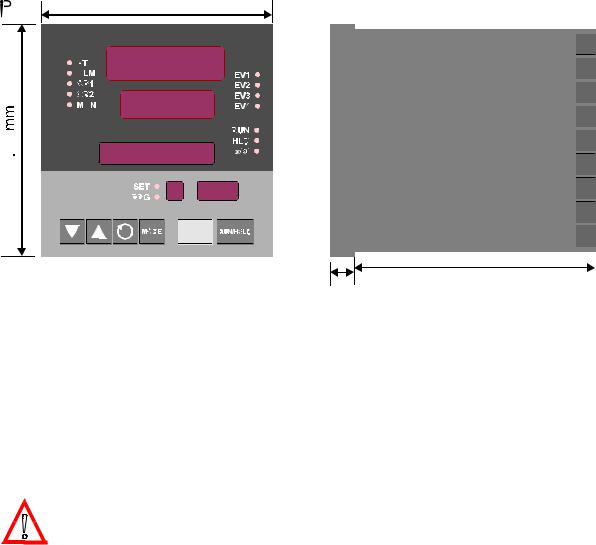
The Setpoint Programmer is 100mm deep (measured from the rear face of the front panel). The front panel is 96mm high and 96mm wide. When panel-mounted, the front panel projects 10mm from the mounting panel. The main dimensions of the Setpoint Programmer are shown in Figure 2-2.
59216-2 |
2-1 |
59216
Figure 2-2 Principal Dimensions
To panel-mount the Setpoint Programmer:
1. Insert the rear of the Setpoint Programmer housing through the cut-out (from the front of the mounting panel) and hold the Setpoint Programmer lightly in position against the panel. Ensure that the panel gasket is not distorted and that the Setpoint Programmer is positioned squarely against the mounting panel. Apply pressure to the front panel bezel only.
CAUTION: Do not remove the panel gasket, as this may result in inadequate clamping of the instrument in the panel.
2. Slide the fixing strap in place (see Figure 2-3) and push it forward until it is firmly in contact with the rear face of the mounting panel (the tongues on the strap should have engaged in matching rachet positions on the Setpoint Programmer housing and the fixing strap springs should be pushing firmly against the mounting panel rear face).
Once the Setpoint Programmer is installed in its mounting panel, it may be subsequently removed from its housing, if necessary, as described in Subsection
3.1.
2-2 |
59216-2 |

59216
Figure 2-3 Panel-mounting the Setpoint Programmer
59216-2 |
2-3 |
59216
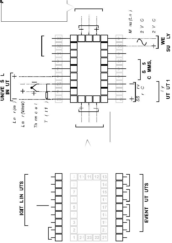
2.3CONNECTIONS AND WIRING
Figure 2-4 Rear Terminals
2-4 |
59216-2 |
59216
2.3.1Mains (Line) Input
The Setpoint Programmer will operate on 96 - 264V AC 50/60Hz mains (line) supply.
The power consumption is approximately 4 VA.
CAUTION: This equipment is designed for installation in an enclosure which provides adequate protection against electric shock. Local regulations regarding electrical installation should be rigidly observed. Consideration should be given to prevention of access to the power terminations by unauthorised personnel. Power should be connected via a two-pole isolating switch (preferably situated near the equipment) and a 1A fuse, as shown in Figure 2-5.
Figure 2-5 Mains (Line) Supply Connections
If the Setpoint Programmer has relay outputs in which the contacts are to carry mains (line) voltage, it is recommended that the relay contact mains (line) supply should be switched and fused in a similar manner but should be separate from the Setpoint Programmer mains (line) supply.
2.3.224V (Nominal) AC/DC Supply
The supply connections for the 24V AC/DC option of the Setpoint Programmer are as shown in Figure 2-6. Power should be connected via a two-pole isolating switch and a 315mA slow-blow (anti-surge Type T) fuse.
Figure 2-6 24V AC/DC Supply Connections
With the 24V AC/DC supply option fitted, these terminals will accept the following supply voltage ranges:
24V |
(nominal) AC 50/60Hz - |
20 - 50V |
24V |
(nominal) DC - |
22 - 65V |
59216-2 |
2-5 |

59216
Table 2-1 Thermocouple Cable Colour Codes
|
|
|
|
|
|
|
|
|
|
|
|
|
|
|
|
|
|
|
|
|
|
|
|
|
|
|
|
|
|
|
|
|
|
|
|
|
|
|
|
|
|
|
|
|
|
|
|
|
|
|
|
|
|
|
|
|
|
|
|
|
|
|
|
|
|
|
|
|
|
|
|
|
|
|
|
|
|
|
|
|
|
|
|
|
|
|
|
|
|
|
|
|
|
|
|
|
|
|
|
|
|
|
|
|
|
|
|
|
|
|
|
|
|
|
|
|
|
|
|
|
|
|
|
|
|
|
|
|
|
|
|
|
|
|
|
|
|
|
|
|
|
|
|
|
|
|
|
|
|
|
|
|
|
|
|
|
|
|
|
|
|
|
|
|
|
|
|
|
|
|
|
|
|
|
|
|
|
|
|
|
|
|
|
|
|
|
|
|
|
|
|
|
|
|
|
|
|
|
|
|
|
|
|
|
|
|
|
|
|
|
|
|
|
|
|
|
|
|
|
|
|
|
|
|
|
|
|
|
|
|
|
|
|
|
|
|
|
|
|
|
|
|
|
|
|
|
|
|
|
|
|
|
|
|
|
|
|
|
|
|
|
|
|
|
|
|
|
|
|
|
|
|
|
|
|
|
|
|
|
|
|
|
|
|
|
|
|
|
|
|
|
|
|
|
|
|
|
|
|
|
|
|
|
|
|
|
|
|
|
|
|
|
|
|
|
|
|
|
|
|
|
|
|
|
|
|
|
|
|
|
|
|
|
|
|
|
|
|
|
|
|
|
|
|
2-6 |
|
|
|
|
|
59216-2 |
||||||||||||||||
59216
2.3.3 Thermocouple Input
The correct type of thermocouple extension leadwire or compensating cable must be used for the entire distance between the Setpoint Programmer and the thermocouple, ensuring that the correct polarity is observed throughout. Joints in the cable should be avoided, if possible. The Setpoint Programmer’s CJC facility must be enabled (normal conditions) for this input (see Subsection 4.3).
NOTE: Do not run thermocouple cables adjacent to power-carrying conductors. If the wiring is run in a conduit, use a separate conduit for the thermocouple wiring. If the thermocouple is grounded, this must be done at one point only. If the thermocouple extension lead is shielded, the shield must be grounded at one point only.
The colour codes used on thermocouple extension leads are shown in Table 2-1.
2.3.4RTD Inputs
The compensating lead should be connected to Terminal 3. For two-wire RTD inputs, Terminals 2 and 3 should be linked. The extension leads should be of copper and the resistance of the wires connecting the resistance element should not exceed 5 ohms per lead (the leads should be of equal resistance).
2.3.5Linear Inputs
For linear mA input ranges, connection is made to Terminals 1 and 4 in the polarity shown in Figure 2-4. For linear mV and V ranges, connection is made to Terminals 2 and 3 in the polarity shown in Figure 2-4. For details of the linear input ranges available, refer to Appendix A.
2.3.6Digital Inputs
These inputs will accept TTL, Open Collector or voltage-free (switch) connections.
A Digital Input Option PCB must be fitted and the External Option parameter (in
Configuration Mode - see Subsection 4.2 of this manual) must be set to inP or both for these terminals to be operable. The degree of external selection/control is defined by the External Selection parameter in Program Define Mode (see Operator’s Manual, Section 8). It is assumed that all external selection/run control functions are enabled for the purposes of this description.
Terminals 31 (R2) to 33 (R0) provide a binary-coded input which is used to select the program:
59216-2 |
2-7 |

59216 |
|
|
|
|
|
|
|
|
Digital Inputs = TTL Level |
|
Digital Inputs = Contavts (switches) |
||||
Digital Inputs |
Program Selected |
|
Digital Inputs |
|
Program Selected |
||
R0 |
R1 |
R2 |
|
R0 |
R1 |
R2 |
|
0 |
0 |
0 |
Program 1 |
Closed |
Open |
Open |
Program 1 |
1 |
0 |
0 |
Program 2 |
Open |
Closed |
Open |
Program 2 |
0 |
1 |
0 |
Program 3 |
Closed |
Closed |
Open |
Program 3 |
1 |
1 |
0 |
Program 4 |
Open |
Open |
Closed |
Program 4 |
0 |
0 |
1 |
Program 5 |
Closed |
Open |
Closed |
Program 5 |
1 |
0 |
1 |
Program 6 |
Open |
Closed |
Closed |
Program 6 |
0 |
1 |
1 |
Program 7 |
Closed |
Closed |
Closed |
Program 7 |
1 |
1 |
1 |
Program 8 |
Open |
Open |
Open |
Program 8 |
For the Program Control inputs, the following convention has been adopted: for
TTL inputs OFF = logic 0, ON = logic 1; for contact (switch) inputs, OFF = open,
ON = closed.
Terminal 30 is the Program Abort control. It is edge-sensitive; an OFF-ON transition at any time will cause an immediate Program Abort.
Terminal 29 provides the remote Run Program/Hold Program control and has an identical effect to that of the Run/Hold key on the front panel. An OFF-ON transition will cause the currently-selected program to be run (or to be resumed if it is currently held); An ON-OFF transition will cause the currently-running program to be held. Powering-up the Setpoint Programmer with this terminal ON will not cause a program to run.
Terminal 28 provides the “x60" program timebase selection. This terminal is level-sensitive: ON (contacts closed) = minutes/seconds, OFF (contacts open) = hours/minutes). When the Setpoint Controller is powered-up, the initially-selected timebase will be according to the level on this terminal at power-up.
NOTE: All remote selection/control functions except the Abort function have precedence over the corresponding front panel controls. The “x60" function will also take precedence over any ”Pre-set x60" parameter setting (see Operator Manual, Section 8).
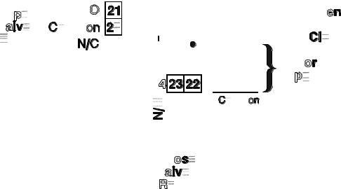
2.3.7Relay Outputs
Outputs 1, 2 and 3: contacts rated at 2A resistive at 120/240V AC.
End of Program/Event outputs: contacts rated at 5A resistive at 120/240V AC.
NOTE: With VMD control, either Output 1 or Output 2 is switched on
(to open or close the valve) However, under fault conditions, both Output 1 and Output 2 relays could be switched on simultaneously.
For safety purposes, an interlock can be included which connects the supply to the motor via the “normally closed” contacts on the Output 1 and Output 2 relays (see Figure 2-7).
2-8 |
59216-2 |
59216
Figure 2-7 Valve Motor Drive Outputs with Interlock
2.3.8SSR Drive Outputs
These outputs produce a time-proportioned non-isolated DC signal (0 - 4.3V nominal, output impedance 250 ohms).
2.3.9DC Outputs
See Appendix A.
2.3.10 Event Outputs
These outputs are only available if the Event Output PCB is fitted and if the External Option parameter in Configuration Mode (see Subsection 4.2 of this manual) is set to either out or both. They are single pole single throw Normally Open relay contacts. For the current segment of the currently-running/held program, these outputs are in the states defined by the Event parameter (see Operator’s Manual,
Section 8) for that segment. 0 = open, 1 = closed.
2.3.11 RS485 Serial Communications Link
The “A” terminal (Terminal 17) on the Setpoint Programmer should be connected to the “A” terminal on the master device; the “B” terminal (Terminal 16) on the
Setpoint Programmer should be connected to the “B” terminal on the master device. Where several Setpoint Programmers are connected to one master port, the master port transceiver in the active state should be capable of driving a load of 12kΩ per Setpoint Programmer; the master port transceiver in the passive state must have pull-up/pull-down resistors of sufficiently low impedance to ensure that
it remains in the quiescent state whilst supplying up to +/-100μA each to the Setpoint Programmer transceivers in the high impedance state.
59216-2 |
2-9 |
59216
SECTION 3
INTERNAL LINKS AND SWITCHES
3.1REMOVING THE SETPOINT PROGRAMMER FROM ITS HOUSING
CAUTION: Before removing the Setpoint Programmer from its housing, 

 ensure that all power has been removed from the rear terminals.
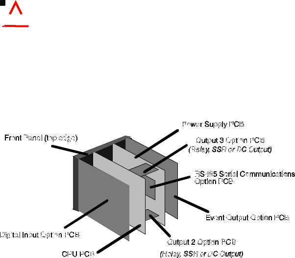
To withdraw the Setpoint Programmer from its housing, simply grip the side edges of the front panel (there is a finger grip on each edge) and pull the panel forwards. This will release the Setpoint Programmer from its rear connectors in the housing and will give access to the PCBs. Take note of the orientation of the Setpoint Programmer for subsequent replacement into the housing.The positions of the PCBs are shown in Figure 3-1.
Figure 3-1 PCB Positions
3-1 |
59216-3 |

59216
Figure 3-2 Removing the Output 2/Output 3 Option PCBs
59216-3 |
3-2 |
59216
3.2REMOVING/REPLACING THE OUTPUT 2/OUTPUT 3 OPTION PCBs
With the Setpoint Programmer removed from its housing:
1.Gently push the rear ends of the CPU PCB and Power Supply PCB apart slightly, until the two tongues on each of the Output 2/Output 3 Option PCBs become dis-engaged - see Figure 3-2B; The Output 2 Option PCB tongues engage in holes in the Power Supply PCB and the Output 3 Option PCB tongues engage in holes on the CPU PCB.
2.Carefully pull the required Option PCB (Output 2 or Output 3) from its connector (Output 2 Option PCB is connected to the CPU PCB and Output 3
Option PCB is connected to the Power Supply PCB) - see Figure 3-2C. Note the orientation of the PCB in preparation for its replacement.
Adjustments may now be made to the link jumpers on the CPU PCB, the Output
2/Output 3 Option PCBs (if DC output) and (if fitted) the DC Output 1 PCB. The replacement procedure is a simple reversal of the removal procedure.
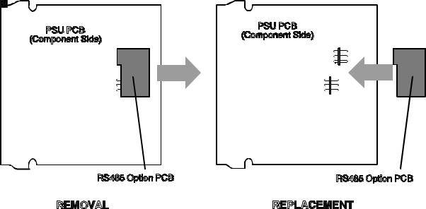
3.3REMOVING/REPLACING THE RS485 COMMUNICATIONS OPTION PCB
The RS485 Communications Option PCB is mounted on the inner surface of the
Power Supply PCB and can be removed when the Setpoint Programmer is removed from its housing (see Subsection 3.1) Figure 3-3 illustrates the removal/replacement procedure. It is not necessary to remove the Output
2/Output 3 Option PCBs to perform this procedure.
Figure 3-3 Removing/Replacing the RS485 Communications Option PCB
3-3 |
59216-3 |

59216
3.4INSTALLING/REMOVING THE DIGITAL INPUT OPTION PCB
The location of the Digital Input Option PCB is shown in Figure 3-4. It is connected to the CPU PCB via a flexi-strip connector, as shown.
Figure 3-4 Location of Digital Input Option PCB and
Event Output Option PCB
To install the Digital Input Option PCB:
1.Hold the PCB approximately in position and carefully insert the free end of the flexi-strip cable into the socket near the bottom edge of the CPU PCB (ensuring that none of the pins on the end of the flexi-strip become bent and that the flexi-strip is not twisted).
2.Fully insert the Digital Input Option PCB into its connector at the rear of the front panel (when the PCB is fully inserted, it will become engaged in the slots above and below its connector).
To remove the Digital Input Option PCB:
1.Dis-engage the PCB from its slots (above and below the connector at the rear of the front panel) and withdraw the PCB clear of the connector.
2.Disconnect the flexi-strip from the connector near the bottom edge of the CPU PCB.
3.Remove the Digital Input Option PCB completely from the instrument.
59216-3 |
3-4 |
59216
3.5INSTALLING/REMOVING THE EVENT OUTPUT OPTION PCB
The location of the Event Output Option PCB is shown in Figure 3-4. It is connected to the CPU PCB via a flexi-strip connector, as shown.
To install the Event Output Option PCB:
1.Hold the PCB approximately in position and carefully insert the free end of the flexi-strip cable into the socket near the top edge of the CPU PCB
(ensuring that none of the pins on the end of the flexi-strip become bent and that the flexi-strip is not twisted).
2.Fully insert the Event Output Option PCB into its connector at the rear of the front panel (when the PCB is fully inserted, it will become engaged in the slots above and below its connector).
To remove the Event Output Option PCB:
1.Dis-engage the PCB from its slots (above and below the connector at the rear of the front panel) and withdraw the PCB clear of the connector.
2.Disconnect the flexi-strip from the connector near the top edge of the
CPU PCB.
3.Remove the Event Output Option PCB completely from the instrument.
3.6REPLACING THE SETPOINT PROGRAMMER IN ITS HOUSING
To replace the Setpoint Programmer, simply align the CPU PCB and Power Supply PCB with their guides and connectors in the housing and slowly but firmly push the
Setpoint Programmer into position.
CAUTION: Ensure that the instrument is correctly orientated. A stop will operate if an attempt is made to insert the instrument in the wrong orientation (e.g. upside-down). This stop must not be over-ridden.
3-5 |
59216-3 |
59216
3.7SELECTION OF INPUT TYPE
The selection of input type is accomplished on link jumpers LJ1/LJ2/LJ3 on the CPU
PCB (see Figure 3-5 and Table 3-1).
Figure 3-5 CPU PCB (Relay/SSR Drive Output 1)
Table 3-1 Input Type Selection
Input Type |
Link Jumper Fitted |
RTD or DC (mV) |
None (parked) |
|
|
Thermocouple |
LJ3 |
|
|
DC (mA) |
LJ2 |
|
|
DC (v) |
LJ1 |
59216-3 |
3-6 |
59216
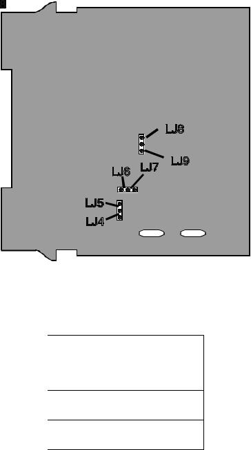
3.8SELECTION OF PRIMARY OUTPUT (OUTPUT 1) TYPE
The required type of Output 1 is selected by Link Jumpers LJ4/LJ5/LJ6/LJ7/LJ8/LJ9 on the PSU PCB (see Figure 3-6 and Table 3-2).
Figure 3-6 PSU PCB Link Jumpers
Table 3-2 Output 1 Type Selection
Output Type |
Link Jumpers |
|
Fitted |
|
|
Relay |
LJ5 & LJ6 |
SSR Drive |
LJ4 & LJ7 |
DC (0 - 10V) |
LJ8 |
DC (0 - 20mA) |
LJ9 |
DC (0 - 5V) |
LJ8 |
DC (4 - 20mA) |
LLJ9 |
3-7 |
59216-3 |
Loading...