

W.E.ST. POS-124-U-PFN, POS-124-U-ETC, POS-124-U-PDP Technical Documentation Manual
Technical Documentation
POS-124-U-PFN
POS-124-U-ETC
Two axes positioning and synchronisation control module with
integrated ProfiNet IO interface and SSI sensor interface
CONTENTS
1 General Information ............................................................................................................................................. 4
1.1 Order number ............................................................................................................................................. 4
1.2 Scope of supply ................................................................................................ .......................................... 4
1.3 Accessories ................................................................................................................................................ 4
1.4 Symbols used ............................................................................................................................................. 5
1.5 Legal notice ................................................................................................................................................ 5
1.6 Safety instructions ....................................................................................................................................... 6
2 Characteristics .................................................................................................................................................... 7
2.1 Device description ....................................................................................................................................... 8
3 Use and application ............................................................................................................................................. 9
3.1 Installation instructions ................................................................................................................................ 9
3.2 Typical system structure .............................................................................................................................10
3.3 Method of operation ...................................................................................................................................10
3.4 Commissioning ..........................................................................................................................................12
4 Technical description ......................................................................................................................................... 13
4.1 Input and output signals .............................................................................................................................13
4.2 LED definitions...........................................................................................................................................14
First section with USB ........................................................................................................................14
Second section (fieldbus) ...................................................................................................................14
4.3 Block Diagram ...........................................................................................................................................15
4.4 Typical wiring .............................................................................................................................................16
4.5 Connection examples .................................................................................................................................16
4.6 Technical data ...........................................................................................................................................17
5 Parameters ....................................................................................................................................................... 18
5.1 Parameter overview ...................................................................................................................................18
5.2 Basic parameters .......................................................................................................................................21
MODE (Switching between parameter groups) ...................................................................................21
5.3 System parameters ....................................................................................................................................21
LG (Changing the language for the help texts) ....................................................................................21
SENS (Malfunction monitoring) ..........................................................................................................21
PASSFB (Password fieldbus) .............................................................................................................21
EOUT (Output signal: READY = OFF) ................................................................................................22
HAND (Manual speed) .......................................................................................................................22
POSWIN (In-position monitoring range) ..............................................................................................23
VMODE (Selecting the control mode) .................................................................................................23
5.4 Input Output parameters.............................................................................................................................24
SELECT:X (Type of position sensors) ................................................................................................24
VRAMP (Ramp time for external speed demand) ................................................................................24
SIGNAL:U (Type and polarity of the output signal) ..............................................................................25
SYS_RANGE (Working stroke) ..........................................................................................................25
SIGNAL (Type of input) ......................................................................................................................25
N_RANGE (Nominal range of the sensor)...........................................................................................26
OFFSET (Sensor zero correction) ......................................................................................................26
SSI:POL (Direction of the sensor signal) .............................................................................................26
SSI:RES (Signal resolution) ...............................................................................................................26
SSI:BITS (Number of bits) ..................................................................................................................27
SSI:CODE (Signal coding) .................................................................................................................27
SSI:ERRBIT (Position of the “out of range” bit) ...................................................................................27
5.5 Positioning controller ..................................................................................................................................28
ACCEL (Acceleration in NC mode) ..................................................................................................... 28
Page 2 of 65 POS-124-U-Ethernet 08.11.2018
VMAX (Maximum speed in NC Mode) ................................................................................................28
V
(Loop gain setting) ........................................................................................................................28
0
A (Acceleration ramp time) .................................................................................................................29
D (Deceleration / braking distance) .....................................................................................................29
PT1 (Timing of the controller) .............................................................................................................30
CTRL (Deceleration characteristics) ...................................................................................................30
MIN (Deadband compensation) ..........................................................................................................31
MAX (Output scaling) .........................................................................................................................31
TRIGGER (Response threshold for the MIN parameter) ......................................................................31
OFFSET (Zero correction)..................................................................................................................32
5.6 Synchronous controller ...............................................................................................................................33
SYNCMODE (Operation mode synchronous run)................................................................................33
SYNCWIN (synchronization monitoring range)....................................................................................34
SYNC (Control parameters) ...............................................................................................................34
5.7 Special functions ........................................................................................................................................35
Drift compensation / high accurate positioning ....................................................................................35
DC:AV (Activation value)....................................................................................................................36
DC:DV (Deactivation value) ...............................................................................................................36
DC:I (Integration time)........................................................................................................................36
DC:CR (Integrator limitation) ..............................................................................................................36
5.8 Special commands .....................................................................................................................................37
AINMODE (Input scaling mode) .........................................................................................................37
AIN (Analogue input scaling) ..............................................................................................................37
ETC_LOOP (Transfer rate) ................................................................................................................38
5.9 PROCESS DATA (Monitoring) ....................................................................................................................38
6 Common device functions .................................................................................................................................. 39
6.1 Failure monitoring ......................................................................................................................................39
6.2 Troubleshooting .........................................................................................................................................39
7 EtherCAT IO interface ....................................................................................................................................... 41
7.1 ETHERCAT CoE........................................................................................................................................41
7.2 EtherCAT installation .................................................................................................................................41
7.3 EtherCAT access handling ................................................................................................ .........................41
7.4 EtherCAT device profiles (ESI) ...................................................................................................................42
7.5 Standard Objects .......................................................................................................................................43
8 ProfiNet IO RT interface ..................................................................................................................................... 44
8.1 PROFINET IO function ...............................................................................................................................44
8.2 ProfiNet Installation guideline .....................................................................................................................44
8.3 PROFINET address assignment .................................................................................................................44
8.4 Device data file (GSDML) ................................ ...........................................................................................45
9 Process data ..................................................................................................................................................... 46
9.1 Data sent to the device...............................................................................................................................46
9.2 Data sent to Fieldbus .................................................................................................................................50
10 Parameterizing via Fieldbus ............................................................................................................................... 54
10.1 Procedure ..................................................................................................................................................54
10.2 Parameterlist .............................................................................................................................................55
11 Profinet – Driver Blocks for Simatic – Controllers ................................................................................................ 56
11.1 TIA – Portal ...............................................................................................................................................56
11.2 STEP7 – classic .........................................................................................................................................59
11.3 Common Properties ...................................................................................................................................62
12 Updating the module internal driver software for Profinet..................................................................................... 64
13 Notes ................................................................................................................................................................ 65
Page 3 of 65 POS-124-U-Ethernet 08.11.2018

1
1 General Information
1.1 Order number
Two axes positioning controller with programmable output (±10 V differential voltage or 4… 20 mA), ana-
logue or SSI sensor interface and optional synchronous control.
POS-124-U-PFN-21401 ProfiNet IO interface
POS-124-U-ETC-2131 EtherCAT IO interface
Alternative products
POS-124-U-PDP Version of the controller with ProfibusDP interface.
1.2 Scope of supply
The scope of supply includes the module including the terminal blocks which are a part of the housing.
The Profibus plug, interface cables and further parts which may be required should be ordered separately.
This documentation can be downloaded as a PDF file from www.w-e-st.de.
1.3 Accessories
WPC-300 Start-Up-Tool (download: www.w-e-st.de/produkte/software)
The number of the version consists of the hardware version (first two digits) and the software version (last two digits).
Because of the development of the products, these numbers can vary. They are not strictly necessary for the order. We
will always deliver the newest version.
Page 4 of 65 POS-124-U-Ethernet 08.11.2018

1.4 Symbols used
General information
Safety-related information
1.5 Legal notice
W.E.St.
Gewerbering 31
D-41372 Niederkrüchten
Tel.: +49 (0)2163 577355-0
Fax.: +49 (0)2163 577355 -11
Homepage: www.w-e-st.de or www.west-electronics.com
EMAIL: info@w-e-st.de
Date: 08.11.2018
The data and characteristics described herein serve only to describe the product. The user is required to
evaluate this data and to check suitability for the particular application. General suitability cannot be inferred
from this document. We reserve the right to make technical modifications due to further development of the
product described in this manual. The technical information and dimensions are non-binding. No claims may
be made based on them.
This document is protected by copyright.
Elektronik GmbH
Page 5 of 65 POS-124-U-Ethernet 08.11.2018
1.6 Safety instructions
Please read this document and the safety instructions carefully. This document will help to define the product
area of application and to put it into operation. Additional documents (WPC-300 for the start-up software) and
knowledge of the application should be taken into account or be available.
General regulations and laws (depending on the country: e.g. accident prevention and environmental protection) must be complied with.
These modules are designed for hydraulic applications in open or closed-loop control circuits. Uncontrolled movements can be caused by device defects (in the hydraulic module or
the components), application errors and electrical faults. Work on the drive or the electronics
must only be carried out whilst the equipment is switched off and not under pressure.
This handbook describes the functions and the electrical connections for this electronic assembly. All technical documents which pertain to the system must be complied with when
commissioning.
This device may only be connected and put into operation by trained specialist staff. The instruction manual must be read with care. The installation instructions and the commissioning
instructions must be followed. Guarantee and liability claims are invalid if the instructions are
not complied with and/or in case of incorrect installation or inappropriate use.
CAUTION!
All electronic modules are manufactured to a high quality. Malfunctions due to the failure of
components cannot, however, be excluded. Despite extensive testing the same also applies
for the software. If these devices are deployed in safety-relevant applications, suitable external measures must be taken to guarantee the necessary safety. The same applies for faults
which affect safety. No liability can be assumed for possible damage.
Further instructions
The module may only be operated in compliance with the national EMC regulations. It is
the user’s responsibility to adhere to these regulations.
The device is only intended for use in the commercial sector.
When not in use the module must be protected from the effects of the weather, contami-
nation and mechanical damage.
The module may not be used in an explosive environment.
To ensure adequate cooling the ventilation slots must not be covered.
The device must be disposed of in accordance with national statutory provisions.
Page 6 of 65 POS-124-U-Ethernet 08.11.2018

2 Characteristics
This electronic module has been developed for controlling hydraulic positioning drives.
Both axes can be controlled independently or also be driven in synchronous mode via fieldbus.
The differential outputs are provided for the control of proportional valves with integrated or external electron-
ics (with differential input). Alternatively the output can be parameterized to 4… 20 mA. This module is in-
tended for the connection with analogue position sensors 0...10V or 4...20mA (scalable) or digital SSI sensor
interfaces.
The internal monitoring sends information about error and operating states via the fieldbus connection to the
master controller. The operational readiness is reported via a digital output, too.
Typical applications: Positioning control or synchronization control with hydraulic axes.
Features
Two independent positioning axes
Can be combined for synchronized control
Command position value parameter, actual value response, control bytes and status bytes via
ProfiNet or EtherCAT fieldbus
SSI-Sensor interface or analogue sensor interface (0….10V or 4…20mA)
Simple and user-friendly sensor scaling
Position resolution of 0.005 mm/s
Principle of stroke-dependent deceleration for the shortest positioning time or NC profile
generator for constant speed
Highly accurate positioning
Advanced position control with PT1 controller, Drift compensation and Fine positioning
Superimposed synchronization controller with PT1 (optimal for hydraulic applications)
Optimal use with zero lapped control valves
Synchronization control in Master/Slave or average value mode
Fault diagnosis and extended function checking
Simplified parameterization with WPC-300 software
Page 7 of 65 POS-124-U-Ethernet 08.11.2018
1 2 3 4
5 6 7 8
9 10 11 12
14 15 1613
Ready A B
46 47 4845
42 43 4441
34 35 3633
38 39 4037
30 31 3229
26 27 2825
18 19 2017
W.E.ST.
25 26 272841 42 43
44
V:
ID:
D-41372 Niederkrüchten
Homepage: http://www.w-e-st.de
W.E. ST.
Elektronik
Add.:Date:
Made in Germany
454647 48
RUN
ERR
131415 16
13 14 15
16
293031 32
114,0000 mm
67,5000 mm
99,0000 mm
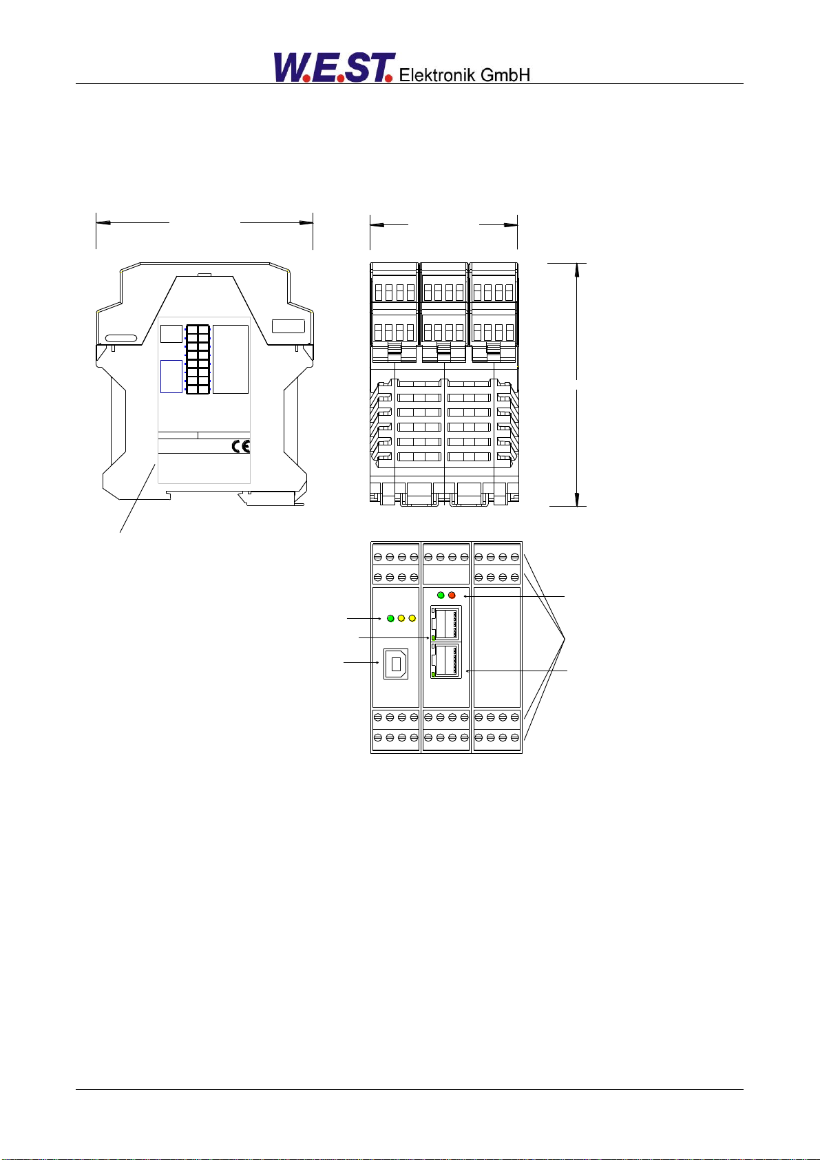
Typenschild und Anschlussbelegung
Type plate and terminal pin assignment
Feldbusstatus
Fieldbus state
Klemmblöcke (steckbar)
Terminals (removable)
Feldbusschnittstelle
Fieldbus interface
Aktivität
Activity
USB
LEDs
2.1 Device description
Page 8 of 65 POS-124-U-Ethernet 08.11.2018

3 Use and application
3.1 Installation instructions
This module is designed for installation in a shielded EMC housing (control cabinet). All cables which
lead outside must be screened; complete screening is required. It is also a requirement that no
strong electro-magnetic interference sources are installed nearby when using our control and regulation modules.
Typical installation location: 24V control signal area (close to PLC)
The devices must be arranged in the control cabinet so that the power section and the signal section
are separate from each other.
Experience shows that the installation space close to the PLC (24 V area) is most suitable. All digital
and analogue inputs and outputs are fitted with filters and surge protection in the device.
The module should be installed and wired in accordance with the documentation bearing in mind
EMC principles. If other consumers are operated with the same power supply, a star- connected
ground wiring scheme is recommended. The following points must be observed when wiring:
The signal cables must be laid separately from power cables.
Analogue signal cables must be shielded.
All other cables must be screened if there are powerful interference sources (frequency
converters, power contactors) and cable lengths > 3m. Inexpensive SMD ferrites can be
used with high-frequency radiation.
The screening should be connected to PE (PE terminal) as close to the module as possi-
ble. The local requirements for screening must be taken into account in all cases. The
screening should be connected to at both ends. Equipotential bonding must be provided
where there are differences between the connected electrical components.
With longer lengths of cable (>10 m) the diameters and screening measures should be
checked by specialists (e.g. for possible interference, noise sources and voltage drop).
Particular care is required with cables of over 40 m in length – the manufacturer should
be consulted if necessary.
A low-resistance connection between PE and the mounting rail should be provided. Transient inter-
ference is transmitted from the module directly to the mounting rail and from there to the local earth.
Power should be supplied by a regulated power supply unit (typically a PELV system complying with
IEC364-4-4, secure low voltage). The low internal resistance of regulated power supplies gives better interference voltage dissipation, which improves the signal quality of high-resolution sensors in
particular. Switched inductances (relays and valve coils connected to the same power supply) must
always be provided with appropriate overvoltage protection directly at the coil.
Page 9 of 65 POS-124-U-Ethernet 08.11.2018
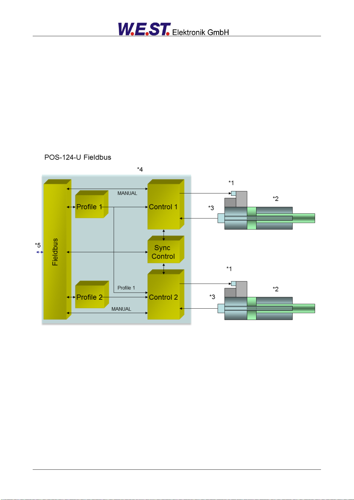
3.2 Typical system structure
This minimal system consists of the following components:
(*1) Proportional valve with OBE
(*2) Hydraulic cylinder
(*3) Position sensor
(*4) POS-124-U-PFN control module
(*5) interface to PLC with analogue and digital signals
3.3 Method of operation
This control module supports simple point-to-point positioning with hydraulic drives. The system works based
on the principle of stroke-dependent deceleration, i.e. the control gain (deceleration stroke) is set via parameters D:A and D:B. Alternatively it can also function in NC-Modus by setting the loop gain parameters. In this
mode the drive will move with controlled velocity to the target position.
The deceleration characteristics can be set linearly (LIN) or approximately quadratically (SQRT1) via the
CTRL parameter. For normal proportional valves SQRT1 is the input setting.
For control valves with a linear flow curve it depends on the application. If LIN is selected for these valves a
significantly shorter deceleration distance can often be set (D:A and D:B).
Page 10 of 65 POS-124-U-Ethernet 08.11.2018
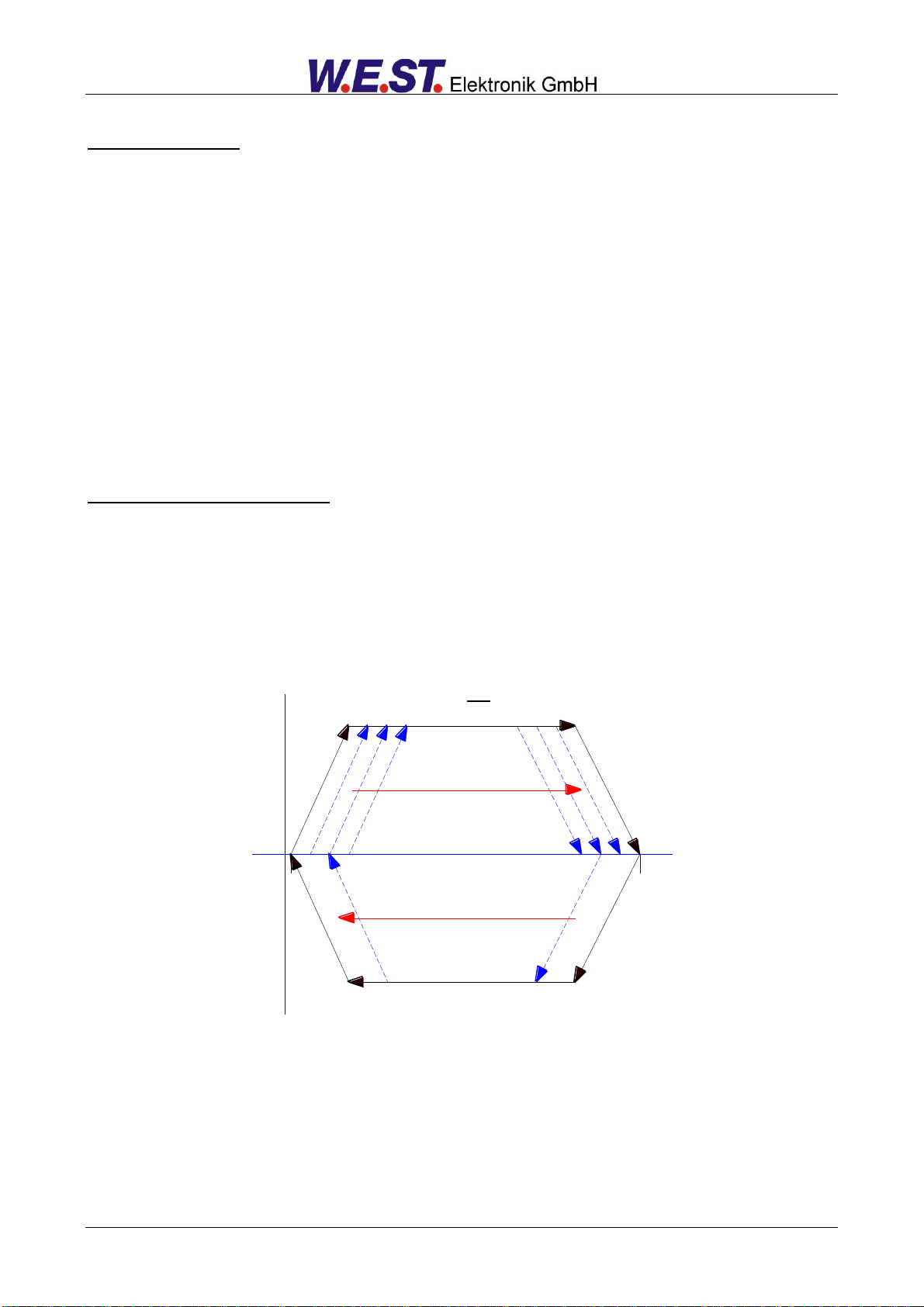
V+
V+
A:A D:A
A:B
D:B
MAX:A
MAX:B
driving out
volumetric flow
P-A
and B-T
control direction
control direction
driving in
Positioning sequence:
The positioning is controlled via Fieldbus. After switching on the ENABLE input, the command position (or
target position) is set equal to the actual position of the sensor and the axis stays in closed loop position control mode. The READY output indicates that the system is generally ready for operation. After setting the
START-signal, the preset command value will be taken over. The axis immediately will drive to this new command position and indicates reaching it by setting the InPos output.
The Poswin output stays active as long as the axis is within the preset Poswin window and the START input
is active. The driving velocity is regulated by a signal received by the fieldbus interface. The axis moves with
a limited speed according to this preset value.
The axis can be driven in manual mode (START is off) using the control bits HAND+ or HAND-. The velocity
is programmable. When the HAND signal is deactivated, the command position is set to the actual position
and the system stays in closed loop position control mode.
Setting the synchronous bit (GL) will synchronize both axes and the synchronization controller is overriding
the position controller of axes 2. Axes 2 is now following axes 1 according to the master-slave-principle.
In order to achieve a reliable synchronous control, the maximum speed should be limited to about 70… 80 %
of the possible speed. For compensating for deviations the slave axis must have the ability to move faster
than the master axis. This control margin is necessary and has to be considered during the system design.
Influences on positioning accuracy:
The positioning accuracy is determined by the hydraulic and mechanical conditions. The right choice of valve
is therefore a decisive factor. In addition, two mutually contradictory requirements (short position time and
high accuracy) must be taken into account when designing the system.
The electronic limitations lie mainly in the resolution of the analogue signals, although with our modules a
resolution of < 0.01% only needs to be considered with long positions. In addition, the linearity of the individual signal points (PLC, sensor and control module) must be considered. The worst-case scenario is that a
system-specific absolute fault occurs.
The repeat accuracy is, however, not affected by this.
Page 11 of 65 POS-124-U-Ethernet 08.11.2018

Step
Task
Installation
Install the device in accordance with the circuit diagram. Ensure it is wired correctly and that the signals are well shielded. The device must be installed in a protective housing (control cabinet or similar).
Switching on for the
first time
Ensure that no unwanted movement is possible in the drive (e.g. switch off the hydraulics). Connect an ammeter and check the current consumed by the device. If
it is higher than specified there is an error in the wiring. Switch the device off immediately and check the wiring.
Setting up communication
Once the power input is correct the PC (notebook) should be connected to the serial interface. Please see the WPC-300 program documentation for how to set up
communication.
Further commissioning and diagnosis are supported by the operating software.
Pre-parameterisation
Now set up the following parameters (with reference to the system design and circuit diagrams):
SYSRANGE, SENSOR SETTINGS, POLARITY, ACCELERATION and
DECELERATION.
Pre-parameterisation is necessary to minimise the risk of uncontrolled movements.
Parameterise specific settings for the control element (MIN for following error
compensation and MAX for maximum velocity).
Reduce the speed limitation to a value which is uncritical for the application.
Control signals
Check the control signal with a voltmeter. The control signals (PIN 15 to PIN16
and PIN19 to PIN20) lies in the range of ± 10V. In the current state it should show
0V. Alternatively, if current signals are used, approx. 0 mA should flow.
CAUTION! This signal depends on the EOUT setting.
Field communication
Activate the fieldbus communication and check whether the right values and bits
are send to the module.
Switching on the
hydraulics
The hydraulics can now be switched on. The module is not yet generating a
signal. Drives should be at a standstill or drift slightly (leave its position at a slow
speed).
Activating ENABLE
CAUTION! Drives can now leave their position and move to an end position at full
speed. Take safety measures to prevent personal injury and damage.
Drives stay in the current position (with ENABLE the actual position is accepted
as the required position). If the drive moves to an end position, the polarity is
probably wrong.
Activating START
With the start signal the demand value on the analogue demand value input is accepted and the axis moves to the predefined target position.
If START is disabled the axis stops in the preset deceleration distance D:S.
Manual (HAND) operation
If START is disabled the axis can be moved manually with HAND+ or HAND- . After disabling the HAND signal, the axis stops in a controlled manner at the current
position.
Optimize controller
Now optimize the controller parameters according to your application and your requirements.
3.4 Commissioning
Page 12 of 65 POS-124-U-Ethernet 08.11.2018

Connection
Supply
PIN 3, PIN 31 and
PIN 35
Power supply (see technical data)
PIN 4, PIN 32 and
PIN 36
0 V (GND) connection.
Connection
Analogue signals
PIN 11
0 V (GND), potential for analogue input signals, internally connected to PIN 4
PIN 12
0 V (GND), potential for analogue output signals, internally connected to PIN 4
PIN 13
Analogue input: position actual value (X1), signal range 0… 10V or 4… 20 mA, scalable
PIN 14
Analogue input: position actual value (X2), signal range 0… 10V or 4… 20 mA, scalable
PIN 15 / 16
Valve control signal axis 1.
Type of signal and polarity can be selected by the parameter SIGNAL:U1.
PIN 19 / 20
Valve control signal axis 2.
Type of signal and polarity can be selected by the parameter SIGNAL:U2.
Connection
SSI sensors
PIN 33
Power supply for sensor 1
PIN 34
0 V (GND) for sensor 1
PIN 37
CLK +
PIN 38
CLK -
PIN 39
DATA +
PIN 40
DATA -
PIN 47
Power supply for sensor 2
PIN 48
0 V (GND) for sensor 2
PIN 41
CLK +
PIN 42
CLK -
PIN 43
DATA +
PIN 44
DATA -
Connection
Digital inputs and outputs
PIN 8
Enable input:
This digital input signal initializes the application. The signal will be combined with the soft-
ware enable of the corresponding axis.
PIN 1
READY output:
ON: The module is enabled; there are no discernible errors.
OFF: Enable is deactivated or an error has been detected.
4 Technical description
4.1 Input and output signals
Page 13 of 65 POS-124-U-Ethernet 08.11.2018

LEDs
Description of the LED function
GREEN
Identical to the READY output.
OFF: No power supply or ENABLE is not activated
ON: System is ready for peration
Flashing: Error discovered
Only active when SENS = ON
YELLOW A
STATUS output.
OFF: The axis 1 is outside the INPOS window.
ON: The axis 1 is within the INPOS window.
YELLOW B
STATUS output.
OFF: The axis 2 is outside the INPOS window.
ON: The axis 2 is within the INPOS window.
GREEN +
YELLOW A+B
1. Chasing light (over all LEDs): The bootloader is active. No normal functions are
possible.
2. All LEDs flash shortly every 6 s: An internal data error was detected and corrected
automatically! The module still works regularly. To acknowledge the error the module
has to be cycle powered.
YELLOW A +
YELLOW B
Both yellow LEDs flash oppositely every 1 s: The nonvolatile stored parameters are inconsistent! To acknowledge the error, the data have to be saved with the SAVE command
or the corresponding button in the WPC.
LEDs
Description of the LED function
GREEN
at ports
Green LEDs shows network traffic at the relating port.
OFF: No connection available
ON: Active network connected
Flashing: Existing data traffic
GREEN
The green RUN LED indicates the status of the central communication processor.
OFF: Bus not started / Initializing
Flashing: Status EtherCAT: Safe Operational
Status ProfiNet: wait for data
Flickering: Status EtherCAT: Status ProfiNet: Failure
ON: Connected and active
RED
The red ERR LED indicates a faillure state
OFF: No Error.
Flashing: EtherCAT: No communication (PLC-Faiilure, lost frames)
ProfiNet: Node flash test
ON: ProfiNet: Failure in the data communication
4.2 LED definitions
First section with USB
Second section (fieldbus)
Page 14 of 65 POS-124-U-Ethernet 08.11.2018
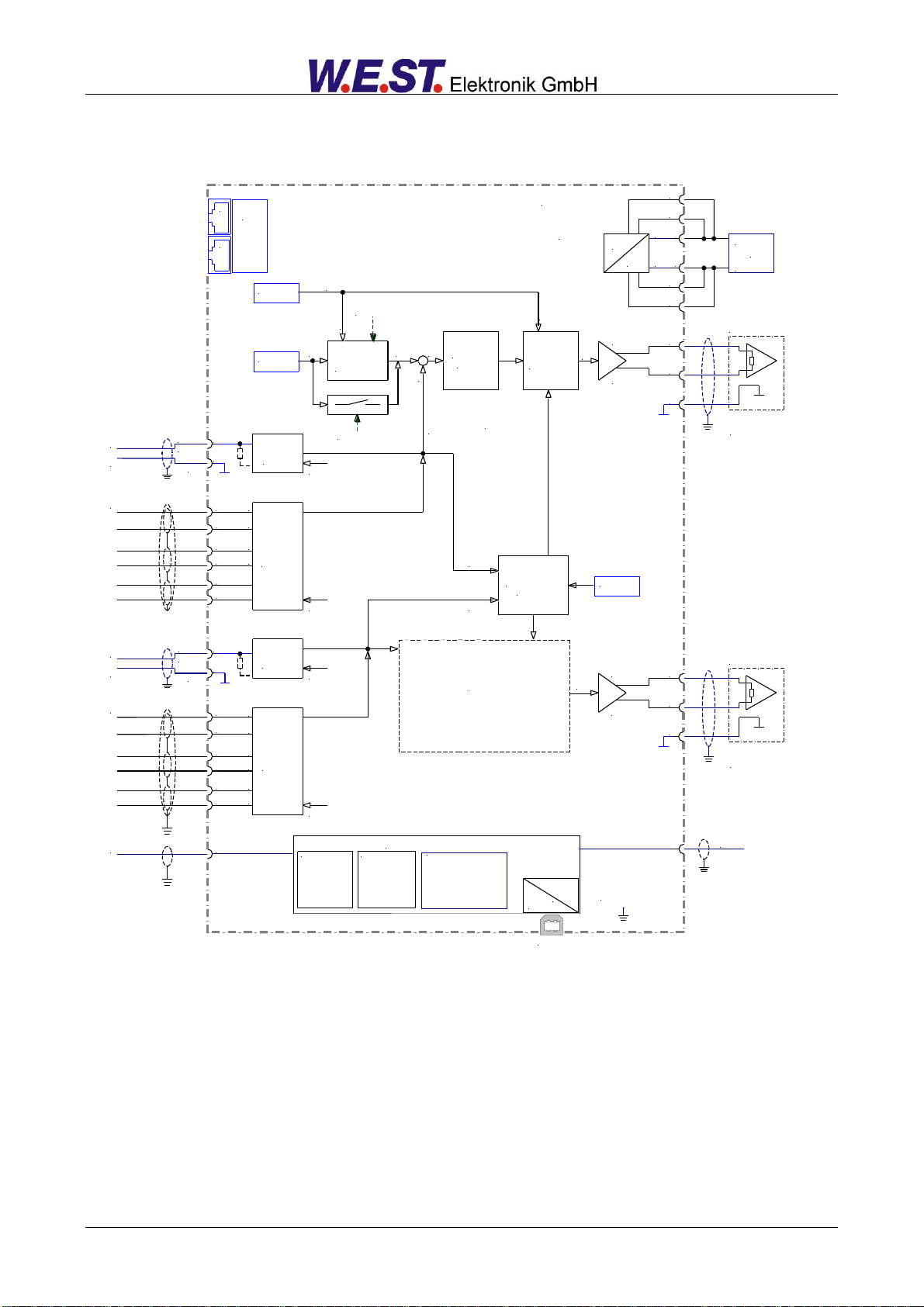
4.3 Block Diagram
POS-124-U-Ethernet
24 V
PE via DIN-RAIL
15
16
12
1
Output: A
Output: B
8
Ready
Enable
24 V output
USB Type B
Differentialinput
13
0 V
11
ANA Feedback
Position 1
Output
Adaptation
24 V input
wa1
x1
u1
Internal Power
3
4
0 V
Position
via Fieldbus
Control program
v1
Current mode: 4... 20 mA
PIN 15 = +, PIN 12 = GND
Profile
Generator
VMODE = NC
0..10V
4..20mA
0 V
Control
Function
SDD or NC
mode
Output
limitation
DC
DC
24 V
0 V
PELV
-
e1w1
VMODE = SDD
Speed
35
32
14
0 V
11
ANA Feedback
Position 2
Input
Scaling
0..10V
4..20mA
0 V
19
20
18
Output: A
Output: B
Differentialinput
AXIS 1
AXIS 2
u2
Current mode: 4... 20 mA
PIN 19 = +, PIN 18 = GND
36
31
47
48
41
42
43
44
24 V
0 V
CLK+
CLK-
DATA+
DATA-
INPX = SSI
SSI Feedback
Position 2
Speed
via Fieldbus
SSI
Sensor
33
34
37
38
39
40
24 V
0 V
CLK+
CLK-
DATA+
DATA-
INPX = SSI
SSI Feedback
Position 1
INPX = ANA
INPX = ANA
Synchronous
Controller
MS or AV
Enable Sync.
via Fieldbus
x1
x2
Serial
57600 Bd
8N1
USB
RJ45
RJ45
Fieldbus
Adaption
Input
Scaling
SSI
Sensor
Support
- Real time function
- communication
- Error handling
Diagnostics
- Remote control
- Process data
- Error information
Send to the Fieldbus
- Status informations
- System errors
- command position
- feedback position
Page 15 of 65 POS-124-U-Ethernet 08.11.2018
power
supply
24V
0V
24
232221
32313029
20191817
GND
+24 V DC
-> ENABLE
+/- 10 V (4...20mA)
to valve no. 1
8765
16151413
1211109
4321
0..10V, 4..20mA
sensor inputs
13 = X1, 14 = X2
+/- 10 V (4...20mA)
to valve no. 2
power supply
communication module
393837
48474645
44434241
36353433
CLKCLK+
DATADATA+
GND
+24 V DC
SSI 2
sensor interface
40
SSI 1
sensor interface
CLK+
CLKDATA+
DATA-
+24 V DC
GND
PE clamp
PE clamp
<- READY
RJ45
OUT
RJ45
IN
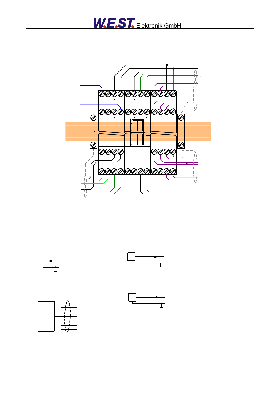
+In PIN 13 or 14
PIN 12 (GND)
AIN:W 2000 1600 2000 C ( für 0... 100%)
0... 10 V feedback signal
+In PIN 13 or PIN 14
In PIN 12 (GND)
sensor with 4... 20 mA (two wire connection)
z. B. 24 V
+In PIN 13 or 14
PIN 12 (GND)
AIN:W 2000 1600 2000 C ( für 0... 100%)
sensor with 4... 20 mA (three wire connection)
z. B. 24 V
Valve (6 + PE plug) with OBE electronics
A : 24 V supply
B : 0 V supply
C : GND or enable
D : + differential input
E : - differential input
F : diagnostics
PE -
PIN 15
PIN 16
PIN 12
Module
4.4 Typical wiring
4.5 Connection examples
Page 16 of 65 POS-124-U-Ethernet 08.11.2018

Supply voltage (Ub)
Current requirement
External protection
[VDC]
[mA]
[A]
24 (±10 %)
500
1 medium time lag
Digital inputs
Input resistance
[V]
[V]
[kOhm]
OFF : < 2
ON : > 10
25
Digital outputs
Maximum output current
[V]
[V]
[mA]
OFF: < 2
ON: max. Ub
50
Analogue inputs (sensor and
demand value signal)
Signal resolution
[V]
[mA]
[%]
0… 10; 33 kOhm
4… 20; 250 Ohm
0.01(internally 0.0031) incl. oversampling
Analogue outputs
Voltage
Signal resolution
Current
Signal resolution
[V]
[mA]
[%]
[mA]
[%]
2 x 0… 10; Differential output
5 (max. load)
0.024
4… 20; 390 Ohm maximum load
0.024
SSI interface
-
RS-422 specification, 150 kBaud
Controller sample time
[ms]
1
Serial interface
USB, 9600… 57600 Baud, 1 stop bit, no
parity, Echo Mode
Profinet IO
Data rate
Conformance class
[Mbit/s]
-
100
CC-B
Housing
Snap-on module to EN 50022
PA 6.6 polyamide
Flammability class V0 (UL94)
Weight
[kg]
0,385
Protection class
Temperature range
Storage Temperature
Humidity
[°C]
[°C]
[%]
IP20
-20… 60
-20... 70
< 95 (non-condensing)
Connections
USB-B
11 x 4-pole terminal blocks
2 x RJ45 Ethernet jack
PE: via the DIN mounting rail
EMC
EN61000-6-4: 2007 +A1:2011
EN61000-6-3: 2005
4.6 Technical data
Page 17 of 65 POS-124-U-Ethernet 08.11.2018
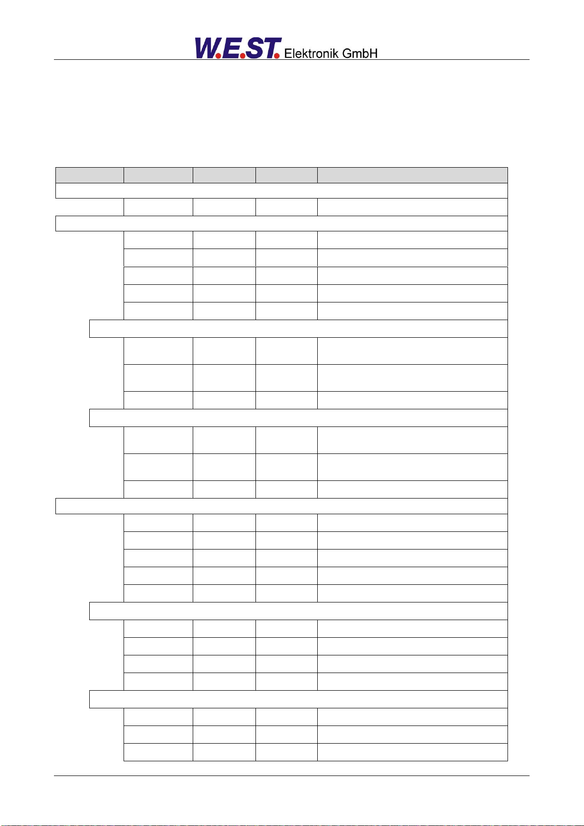
Group
Command
Default
Unit
Description
Basic parameters
MODE
STD
-
Parameter view
System parameters (MODE = SYSTEM)
LG
EN
-
Changes the language of the help texts
SENS
ON
-
Malfunction monitor
PASSFB
0
-
Password for fieldbus parameterization
EOUT_1
0
0,01 %
Output signal if not ready
EOUT_2
0
0,01 %
Output signal if not ready
Axis 1
HAND_1:A
HAND_1:B
3330
-3330
0,01 %
0,01 %
Output signal in manual mode
POSWIN_1:S
POSWIN_1:D
200
5000
µm
µm
Windows of the “in position” monitoring
VMODE_1
SDD
-
Method of positioning
Axis 2
HAND_2:A
HAND_2:B
3330
-3330
0,01 %
0,01 %
Output signal in manual mode
POSWIN_2:S
POSWIN_2:D
200
5000
µm
µm
Windows of the “in position” monitoring
VMODE_2
SDD
-
Method of positioning
Input and output parameters (MODE = IOCONFIG)
SELECT:X
SSI
-
Selection of the sensor signals
VRAMP_1
100
ms
Speed ramp time
VRAMP_2
100
ms
Speed ramp time
SIGNAL_1:U
U+-10
-
Type and polarity of the analogue output
SIGNAL_2:U
U+-10
-
Type and polarity of the analogue output
Axis 1
SYS_RANGE_1
100
mm
Axis working stroke
SIGNAL_1:X
U0-10
-
Type of analogue input
N_RANGE_1:X
100
mm
Sensor length
OFFSET_1:X
0
µm
Sensor offset
Axis 2
SYS_RANGE_2
100
mm
Axis working stroke
SIGNAL_2:X
U0-10
-
Type of analogue input
N_RANGE_2:X
100
mm
Sensor length
5 Parameters
5.1 Parameter overview
Page 18 of 65 POS-124-U-Ethernet 08.11.2018

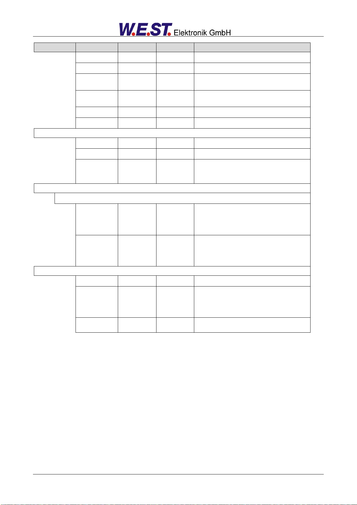
Group
Command
Default
Unit
Description
OFFSET_2:X
0
µm
Sensor offset
SSI connection
SSI_1:POL
+
-
Sensor polarity
SSI_2:POL
+
-
Sensor polarity
SSI:RES
100
10 nm
Sensor resolution
SSI:BITS
24
-
Number of transmitted bits
SSI:CODE
GRAY
-
Type of transmission code
SSI:ERRBIT
0
-
Position of the error bit
Positioning controller 1 (MODE = POS_1)
Positioning VMODE = NC
ACCEL_1
250
mm/s²
Acceleration
VMAX_1
50
mm/s
Maximum velocity
V0_1:A
V0_1:B
V0_1:RES
10
10
1
1/s
1/s
-
Loop gain
Loop gain resolution
Positioning VMODE = SDD
A_1:A
A_1:B
100
100
ms
ms
Acceleration time
D_1:A
D_1:B
D_1:S
25
25
10
mm
mm
mm
Deceleration stroke
Controller
PT1_1
1
ms
PT1-filter time constant
CTRL_1
SQRT1
-
Control characteristic
MIN_1:A
MIN_1:B
0
0
0,01 %
0,01 %
Deadband compensation
MAX_1:A
MAX_1:B
10000
10000
0,01 %
0,01 %
Output scaling
TRIGGER_1
200
0,01 %
Deadband compensation trigger point
OFFSET_1
0
0,01 %
Offset value for the output
Positioning controller 2 (MODE = POS_2)
Positioning VMODE = NC
ACCEL_2
250
mm/s²
Acceleration
VMAX_2
50
mm/s
Maximum velocity
V0_2:A
V0_2:B
V0_2:RES
10
10
1
1/s
1/s
-
Loop gain
Loop gain resolution
Positioning VMODE = SDD
A_2:A
A_2:B
100
100
ms
ms
Acceleration time
D_2:A
D_2:B
D_2:S
25
25
10
mm
mm
mm
Deceleration stroke
Controller common settings / valve adaption
Page 19 of 65 POS-124-U-Ethernet 08.11.2018
Group
Command
Default
Unit
Description
PT1_2
1
ms
PT1-filter time constant
CTRL_2
SQRT1
-
Control characteristic
MIN_2:A
MIN_2:B
0
0
0,01 %
0,01 %
Deadband compensation
MAX_2:A
MAX_2:B
10000
10000
0,01 %
0,01 %
Output scaling
TRIGGER_2
200
0,01 %
Deadband compensation trigger point
OFFSET_2
0
0,01 %
Offset value for the output
Synchronisation Controller (MODE = SYNC)
SYNCMODE
MS
-
Synchronization mode
SYNCWIN
5000
µm
Synchronization error window
SYNC:P
SYNC:V0
SYNC:T1
25
10
80
mm
s-1
ms
P gain (deceleration stroke, SDD)
Loop gain (NC)
Time constant
Special functions (MODE = EXTRA)
Fine positioning / drift compensation
DC_1:AV
DC_1:DV
DC_1:I
DC_1:CR
0
0
2000
500
0,01 %
0,01 %
ms
0,01 %
Point of activation
Point of deactivation
Time constant of the integrator function
Limit of the control range
DC_2:AV
DC_2:DV
DC_2:I
DC_2:CR
0
0
2000
500
0,01 %
0,01 %
ms
0,01 %
Point of activation
Point of deactivation
Time constant of the integrator function
Limit of the control range
Special commands
AINMODE
EASY
-
Input scaling mode
AIN_1:X
AIN_2:X
A: 1000
B: 1000
C: 0
X: V
-
-
0,01 %
-
Free scaling of the analogue inputs (MATH). Replaces SIGNAL, N_RANGE and OFFSET.
Please contact W.E.St. before using these commands.
ETC_LOOP
NORMAL|FAST
-
Cycle time of the data transfer.
Only available when using EtherCAT devices!
Page 20 of 65 POS-124-U-Ethernet 08.11.2018
 Loading...