

Page 1
1
/4 -DIN, 1/8 -DIN & 1/16 - DIN Controllers & Indicators - Product Manual
3 Plug-in Options
Options Modules and Functions
A range of plug-in option modules is available to add additional input, output and
communication functions to the instruments in the range. These modules can be either preinstalled at the time of manufacture, or retrofitted in the field.
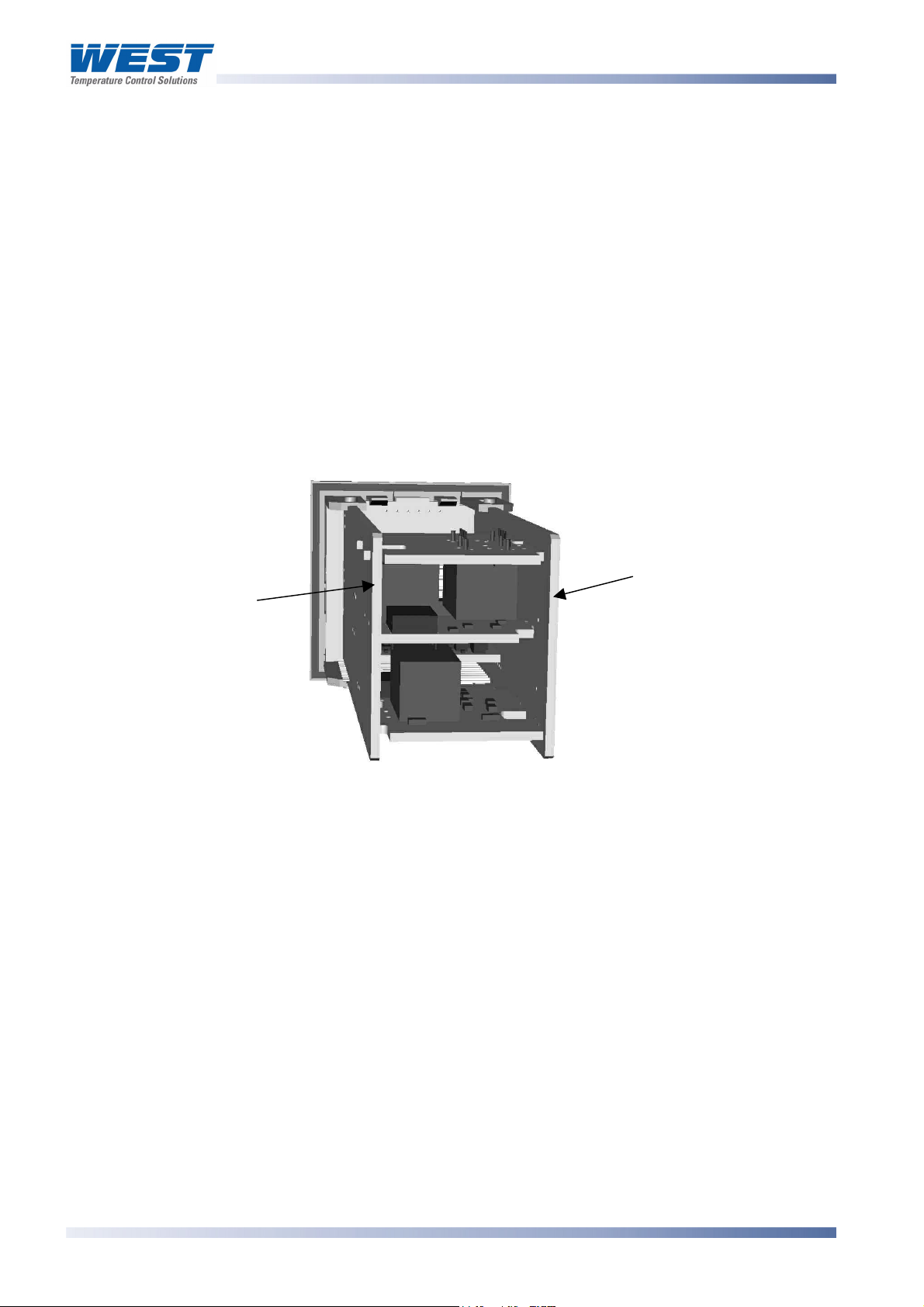
The modules are installed between the instruments main circuit boards into the four option
slots. These are designated as Slots 1, 2, 3, A & B. Installation is detailed below.
Note:
Slot 1 modules cannot be fitted into Slot 2 or 3. Slot 2 & 3 modules cannot be fitted into
Slot 1. Some Slot 2 &3 modules should only be fitted into one of the two slots. This is
detailed in the - Option Module vs. Model Matrix below.
PSU BOARD
CPU BOARD
Figure 4. Typical rear view (uncased) & main board positions
Auto Detection of Option Modules
The instrument automatically detects which option modules have been fitted into each slot.
In Configuration Mode, the menus will change to reflect the options compatible with the
hardware fitted. The modules fitted can be viewed in the products information menu, as
detailed in the Product Information Mode section of this manual.
Page 14 Plug-in Options 59305, Issue 6 – March 2006
Page 2
1
/4 -DIN, 1/8 -DIN & 1/16 - DIN Controllers & Indicators - Product Manual
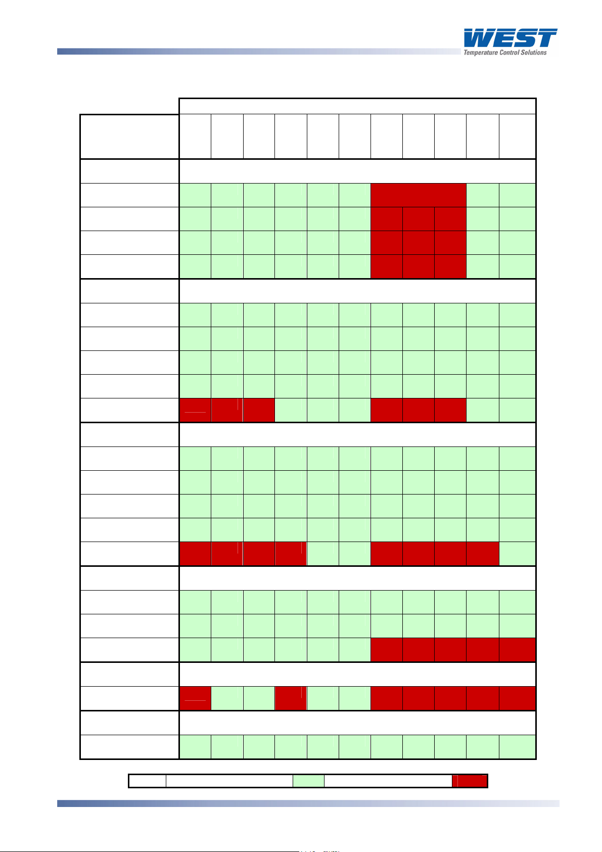
Table 1. Option Module vs. Model Matrix
MODULE PART
NUMBER
& Function
OPTION
SLOT 1
PO1-C10
Relay
PO1-C50
SSR Driver
PO1-C80
Triac
PO1-C21
Linear mA/V DC
OPTION
SLOT 2
PO2-C10
Relay
PO2-C50
SSR Driver
PO2-C80
Triac
PO2-C21
Linear mA/V DC
PO2-W09
Dual Relay
OPTION
SLOT 3
PO2-C10
Relay
PO2-C50
SSR Driver
PO2-C21
Linear mA/V DC
PO2-W08
TransmitterPSU
PO2-W09
Dual Relay
OPTION
SLOT A
PA1-W06
RS485 Comms
PA1-W03
Digital Input
PA1-W04
Basic Aux Input
OPTION
SLOT B
PB1-W0R
Full Aux Input
SOFTWARE &
ACCESSORIES
PS1-CON
Config Software
P6100
P6120
P8100
P4100
MODEL NUMBER
P6170
P8170
P4170
P6700
P8700
P4700
P6010
Fitted with fixed
Limit Relay
P8010
KEY
Option Possible
Option Not Possible
59305, Issue 6 – March 2006 Plug-in Options Page 15
Page 3

1
/4 -DIN, 1/8 -DIN & 1/16 - DIN Controllers & Indicators - Product Manual
Preparing to Install or Remove Options Modules
CAUTION:
Before removing the instrument from it’s housing, ensure that all power has been
removed from the rear terminals.
1. Remove the instrument from its housing by gripping the side edges of the front panel
(there is a finger grip on each edge) and pull the instrument forwards. This will release the
instrument from the rear connectors in the housing and will give access to the PCBs.
2. Take note of the orientation of the instrument for subsequent replacement into the
housing. The positions of the main and option PCBs in the instrument are shown below.
Removing/Replacing Option Modules
With the instrument removed from its housing:
1. To remove or replace modules into Option Slots 1,A or B, it is necessary to gently
separate the CPU and PSU PCBs. This is achieved by detaching the main boards (PSU
and CPU) from the front moulding by lifting first the upper and then lower mounting struts
as shown. This frees the boards from the front. If only Option slots 2 or 3 are to be
changed, this stage is not required as these slots are accessible without separating the
main boards from the front.
Mounting Struts
Option Slot 1
Option Slot A
Option Slot 3
Option Slot 2
Figure 5. Location of Option Modules -
1
/16 DIN Instruments
CAUTION:
Take care not to put undue stress on the ribbon cable attaching the display and
CPU boards.
Page 16 Plug-in Options 59305, Issue 6 – March 2006
Page 4

1
A
/4 -DIN, 1/8 -DIN & 1/16 - DIN Controllers & Indicators - Product Manual
Option Slot B
Option Slot 2
Option Slot 1
CAUTION:
Figure 6. Location of Option Modules -
Mounting Struts
Option Slot A
Option Slot 3
1
/8 & 1/4 DIN Instruments
Take care not to put undue stress on the ribbon cable attaching the display and
CPU boards.
2. Remove or fit the modules into the Option slots as required. The location of the connectors
is shown below. Tongues on each option module locate into a slots cut into the main
boards, opposite each of the connectors.
Option Slot 1
Connectors PL7 & PL8
Option Slot 2
Connector PL4
Option Slot 3
Connector PL4B
Figure 7. Option Module Connectors -
1
/16 DIN Instruments
Option Slot A
Connectors PL5 & PL6
CAUTION:
Check for correct orientation of the modules and that all pins locate correctly into
the socket
59305, Issue 6 – March 2006 Plug-in Options Page 17
Page 5

1
A
/4 -DIN, 1/8 -DIN & 1/16 - DIN Controllers & Indicators - Product Manual
Option Slot B
Connectors PL2A,
PL2B & PL2C
Option Slot 2
Connector PL4
Option Slot 1
Connectors PL7 & PL8
Option Slot A
Connectors PL5 & PL6
Option Slot 3
Connectors PL4B
Figure 8. Option Module Connectors -
1
/8 & 1/4 DIN Instruments
CAUTION:
Check for correct orientation of the modules and that all pins locate correctly into
the socket
Page 18 Plug-in Options 59305, Issue 6 – March 2006
Page 6

1
/4 -DIN, 1/8 -DIN & 1/16 - DIN Controllers & Indicators - Product Manual
Replacing the Instrument in its Housing
With the required option modules correctly located into their respective positions the
instrument can be replaced into its housing as follows:
1. If required, move the CPU and PSU boards back together, taking care to locate the option
module tongues into the slots in the board opposite. Hold the main boards together whilst
relocating them back into the mounting struts on the front panel.
2. Align the CPU and PSU PCBs with their guides and connectors in the housing.
3. Slowly and firmly, push the instrument in position.
CAUTION:
Ensure that the instrument is correctly orientated. A mechanical stop will operate if
an attempt is made to insert the instrument in the wrong orientation, this stop MUST
NOT be over-ridden.
59305, Issue 6 – March 2006 Plug-in Options Page 19
 Loading...