

Page 1
Pro-EC44 2-Loop Graphical Profile Controller & Recorder
PART
NUMBER
AVAILABLE OPTIONS & ACCESSORIES
BOARD
IDENTIFICATION
NUMBER
MODULE SLOT 1
PO1-R10
Single Relay Output for plug-in module slot 1
716/01
PO1-S20
Single SSR Driver Output for plug-in module slot 1
716/02
PO1-T80
Triac Output for plug-in module slot 1
716/03
PO1-C21
Linear mA / Voltage Output for plug-in module slot 1
639/01
MODULE SLOT 2 or 3
PO2-R10
Single Relay Output for plug-in module slot 2 or 3
717/01
PO2-W09
Dual Relay Output for plug-in module slot 2 or 3
644/01
PO2-S20
Single SSR Driver Output for plug-in module slot 2 or 3
717/02
PO2-S22
Dual SSR Driver Output for plug-in module slot 2 or 3
644/02
PO2-T80
Triac module Output for plug-in module slot 2 or 3
647/01
PO2-W08
24VDC Transmitter Power Supply for module slot 2 or 3
642/01
MODULE SLOT A
PA1-W03
Digital Input for plug-in module slot A
641/02
PA1-W04
Basic Auxiliary Input for plug-in module slot A
653/01
PA1-W06
RS485 Serial Communications for plug-in module slot A
680/01
PA1-ETH
Ethernet Communications for plug-in module slot A
707/01
ACCESSORIES
PS1-PRF
Profiler Enable Key-code
PS1-PRW
Blue Control PC Configuration Software & Lead
CAUTION: Plastic pegs prevent fitting of older non-reinforced single relay
modules (board identification numbers 637/01 and 638/01). Fitting the older
relay modules reduces the isolation rating to Basic 240V isolation and is
therefore not recommended.
Remove this peg when fitting Dual Relay Modules.
Board Positions
Note: All dual relay modules have reinforced isolation.
3 Field Upgrade Options
Plug-Modules and Upgradeable Functions
Plug-Modules can be either pre-installed at the time of manufacture, or retrofitted in the field
to expand the capabilities of the controller. Contact your supplier to purchase these items.
Part numbers and circuit board identification numbers for the plug-in modules and
accessories are shown in below:
Pro-EC44 Product Manual - 59540-2 September 2014 Page 4
Page 2
Pro-EC44 2-Loop Graphical Profile Controller & Recorder
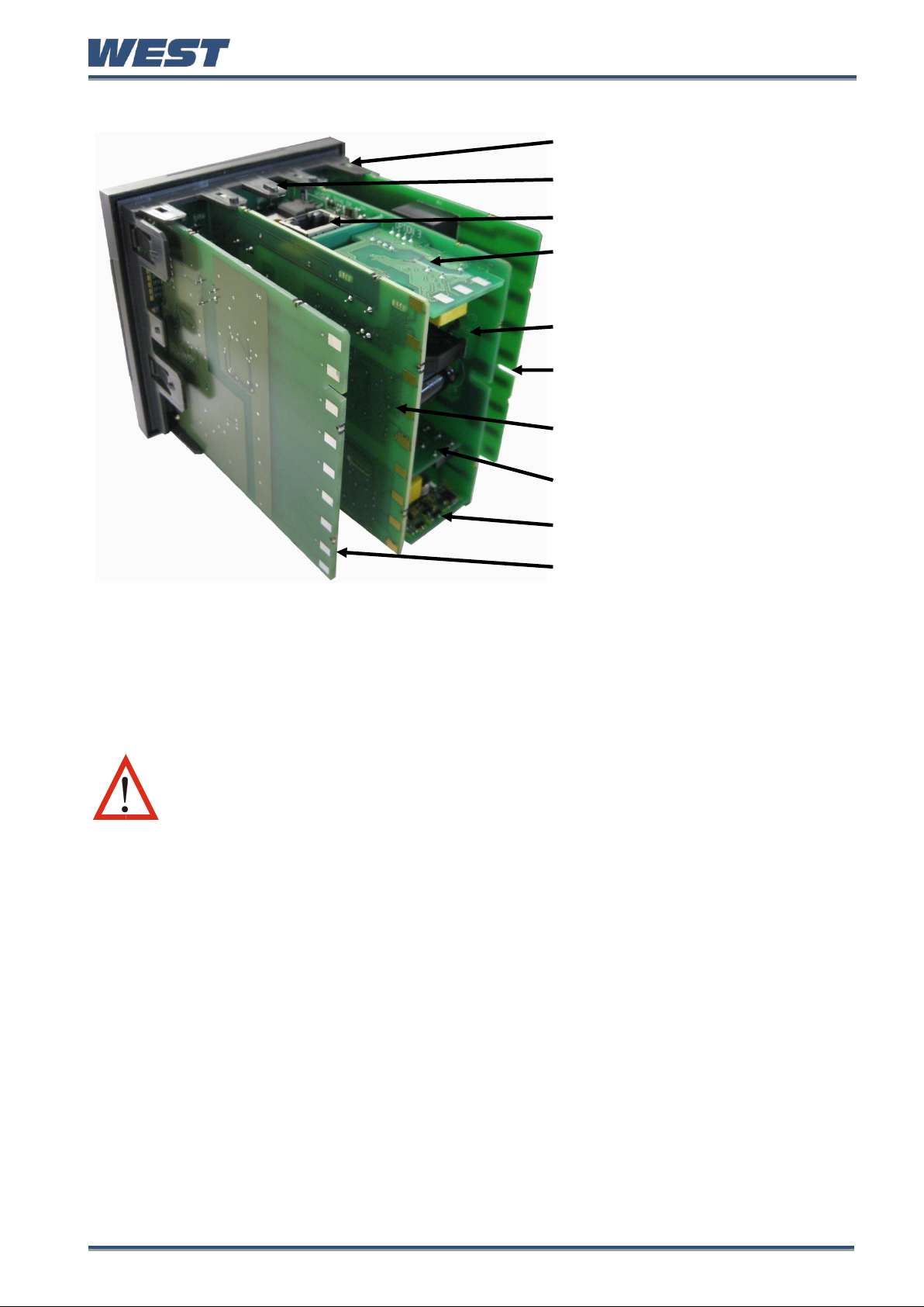
Board Mounting Struts (x4)
Front Panel Removal Latch (x1)
Plug-in Module A
Plug-in Module 3
Power Supply Board
2nd Universal Input & Base
Option 2 Board
1st Universal Input & Base
Option 1 Board
Plug-in Module 1
Plug-in Module 2
USB/Digital Input C Option
Board
CAUTION: Before removing the instrument from its housing, ensure that all
power has been removed from the rear terminals. Modules / boards should
be replaced by a technically competent technician.
Figure 3. Rear view (uncased) & board positions
Preparing to Install or Remove Plug-in Modules
1. Grip the edges of the front panel (there is a finger grip on each edge) and pull it forwards
approximately 10mm, until the Front Panel Removal Latch prevents further movement.
The purpose of the latch is to prevent removal of the instrument without the use of a tool.
2. The Front Panel Removal Latch must be pushed down to allow removal of the instrument.
Using a tool (e.g. screwdriver or pen tip), press down it down through the front central
ventilation hole. This will release the instrument from the case.
3. The internal boards can now be accessed. Take note of the orientation of the instrument
and boards for subsequent replacement into the housing. The positions of the boards,
their mountings and the Front Panel Removal Latch are shown above.
Pro-EC44 Product Manual - 59540-2 September 2014 Page 5
Page 3

Pro-EC44 2-Loop Graphical Profile Controller & Recorder
Main Board Connectors
POWER SUPPLY
BOARD
Transformer Colour
Code
100-240V (Yellow)
24-48V(Blue)
Display Board
Connections
1st UNIVERSAL
INPUT / BASE
OPTION 1 BOARD
Module Slot 3
Connector PL4B
Module Slot A
Connectors PL5, & PL6
Module Slot 1
Connectors PL7 & PL8
PC Configurator
Socket SK1
Module Slot 2
Connector PL4A
CAUTION: Replacement of boards must be carried out by a technically
competent technician. If the Power Supply board does not match the
labelling, users may apply incorrect voltage resulting in irreparable
damage.
This product is designed to allow the user to reconfigure some hardware options in the field
by changing the plug-in modules in slots 1, 2, 3, & A located on the power supply and 1st
universal input boards. The main boards (display/CPU, power supply, inputs 1 & 2 and digital
input/USB) are factory fitted, but may be removed while reconfiguring the plug-in modules.
Take care when re-fitting these boards. Observe the power supply board transformer colour,
and case labelling to check the supply voltage, otherwise irreparable damage may occur.
Figure 4. Main board connectors
Pro-EC44 Product Manual - 59540-2 September 2014 Page 6
Page 4

Pro-EC44 2-Loop Graphical Profile Controller & Recorder
CAUTION: Check for correct orientation of the modules and that all pins
are located correctly.
CAUTION: Before replacing the instrument in its housing, ensure that all
power has been removed from the rear terminals.
CAUTION: Ensure that the instrument is correctly orientated. A mechanical
stop will operate if an attempt is made to insert the instrument in the wrong
orientation, this stop MUST NOT be over-ridden.
Removing/Replacing Option Modules
1. To remove or replace Plug-in Modules 1, 2, 3 or A it is necessary to detach the power
supply and input boards from the front panel by lifting first the upper and then lower
mounting struts.
2. Remove or fit the modules to the connectors on the power supply and input boards. The
location of the connectors is shown below. Plastic pegs prevent fitting of older nonreinforced single relay modules – Remove the peg to fit dual relay modules
3. Assemble the Power Supply and Input boards together. Tongues on each option module
locate into slots cut into the main boards, opposite each of the connectors. Hold the Power
and Input boards together and relocate them back on their mounting struts.
4. Push the boards forward to ensure correct connection to the front Display/CPU board and
re-check the installation of the Option C and/or 2nd Input / Base Option 2 boards if present.
Replacing the Instrument in its Housing
With the required option modules correctly located into their respective positions the
instrument can be replaced into its housing as follows:
1. Hold the Power Supply and Input boards together.
2. Align the boards with the guides in the housing.
3. Slowly and firmly, push the instrument into position in its case.
Auto Detection of Plug-in Modules
The instrument automatically detects which plug-in modules have been fitted into each slot.
The menus and screens change to reflect the options compatible with the hardware. The
modules fitted can be viewed in the product information menu, as detailed in the Product &
Service Information Mode section of this manual.
Pro-EC44 Product Manual - 59540-2 September 2014 Page 7
Page 5

Pro-EC44 2-Loop Graphical Profile Controller & Recorder
CAUTION: Servicing of the Data Recorder/RTC circuit and replacement of
the lithium battery should only be carried out by a technically competent
technician.
Data Recorder Board
If installed, the Data Recorder memory and Real Time Clock (RTC) components are located
on a plug-in daughter board attached to the front Display/CPU board.
Profiler Enabling
If you purchased a controller with the Profiler option installed, these features will be enabled
during manufacture.
Controllers supplied without the Profiler option installed can be upgraded in the field by
purchasing a licence code number from your supplier. A unique code must be purchased to
enable profiling on each controller that requires it.
Entering the Profiler Enable Code
Hold down the L and D keys during the power-up “splash screen”.
Using the D or U keys, enter the 16-character licence code in the displayed screen.
Press R to move on to the next character. Press L to move back to the previous
character.
Press R after entering the final character.
To confirm if profiling is installed in your instrument, check the Controller Feature Information
in Product & Service Information Mode.
Pro-EC44 Product Manual - 59540-2 September 2014 Page 8
 Loading...