

Page 1
Technical Documentation
PID-131-U
Standard PID-Controller
Page 2

W.E.ST.
Elektronik GmbH
CONTENTS
1 General Information.............................................................................................................................................. 4
1.1 Order number ............................................................................................................................................... 4
1.2 Scope of supply ............................................................................................................................................ 4
1.3 Accessories ................................ ................................................................ ................................ .................. 4
1.4 Symbols used ............................................................................................................................................... 5
1.5 Using this documentation ............................................................................................................................. 5
1.6 Legal notice ................................................................................................ ................................ .................. 5
1.7 Safety instructions ........................................................................................................................................ 6
2 Characteristics ..................................................................................................................................................... 7
2.1 Compatibility ................................................................................................................................................. 8
2.2 Device description ........................................................................................................................................ 9
3 Use and application ............................................................................................................................................ 10
3.1 Installation instructions ............................................................................................................................... 10
3.2 Typical system structure ............................................................................................................................. 11
3.3 Method of operation ................................................................................................................................... 11
3.4 Commissioning ........................................................................................................................................... 12
4 Technical description.......................................................................................................................................... 13
4.1 Input and output signals ............................................................................................................................. 13
4.2 LED definitions ........................................................................................................................................... 14
4.3 Circuit diagram ........................................................................................................................................... 15
4.4 Typical wiring.............................................................................................................................................. 16
4.5 Connection examples ................................................................................................................................. 16
4.6 Technical data ............................................................................................................................................ 17
5 Parameters ......................................................................................................................................................... 18
5.1 Parameter overview ................................................................................................................................... 18
5.2 Basic parameters ....................................................................................................................................... 20
LG (Changing the language) ............................................................................................................. 20
MODE (Switching between parameter groups) ................................................................................. 20
SENS (monitoring of the modul functions) ......................................................................................... 20
PIN5 (Function of PIN 5).................................................................................................................... 21
CDWIN (Size of the control deviation window) .................................................................................. 21
EOUT (Output signal if not ready) ..................................................................................................... 21
5.3 Input signal adaptation ............................................................................................................................... 22
SIGNAL (Type of input) ..................................................................................................................... 22
N_RANGE:X (Nominal range of the sensor)...................................................................................... 22
OFFSET:X (Sensor offset) ................................................................................................................. 22
Using the commands SIGNAL:X, N_RANGE:X and OFFSET:X ....................................................... 23
5.4 Ramp and PID control parameters ............................................................................................................. 23
RA (Command signal ramp times) ..................................................................................................... 23
C (PID Control Settings) .................................................................................................................... 24
5.5 Output signal adaptation ............................................................................................................................ 25
MIN (Deadband compensation) ................................ ................................................................ ......... 25
MAX (Output scaling) ........................................................................................................................ 25
TRIGGER (Deadband compensation trigger point) ........................................................................... 25
SIGNAL:U (Output type and polarity) ................................................................................................ 26
5.6 Special commands ..................................................................................................................................... 27
TS (Sample time) ............................................................................................................................... 27
AINMODE (Input scaling mode) ........................................................................................................ 27
AIN (Free analogue input scaling) ..................................................................................................... 28
5.7 PROCESS DATA (Monitoring) ................................................................................................................... 29
Page 2 of 32 PID-131-U-2030 30.12.2015
Page 3

W.E.ST.
6 Appendix ............................................................................................................................................................ 30
6.1 Failure monitoring ....................................................................................................................................... 30
6.2 Troubleshooting .......................................................................................................................................... 30
6.3 Description of the command structure ........................................................................................................ 31
7 Notes ................................................................................................................................................................. 32
Elektronik GmbH
Page 3 of 32 PID-131-U-2030 30.12.2015
Page 4

W.E.ST.
1
Elektronik GmbH
1 General Information
1.1 Order number
PID-131-U-20301 - with analogue ±10 V differential output or 4… 20 mA output and analogue sensor
interface
1.2 Scope of supply
To the scope of supply belongs the module including the terminal blocks which are part of the housing.
The Profibus plug, interface cables and further parts which may be required should be ordered separately.
This documentation can be downloaded as a PDF file from www.w-e-st.de.
1.3 Accessories
WPC-300 - Start-Up-Tool (downloadable from our homepage – products/software)
The number of the version consists of the hardware-version (first two digits) and the software-version (second two digits).
Because of the development of the products these numbers can vary. They are not strictly necessary for the order. We will
always deliver the newest version.
Page 4 of 32 PID-131-U-2030 30.12.2015
Page 5

W.E.ST.
Elektronik GmbH
1.4 Symbols used
General information
Safety-related information
1.5 Using this documentation
Structure of the documentation:
The standard product is described up to chapter 6. The extensions like POWER STAGE or SSI-INTERFACE
are described in the chapters ADDITIONAL INFORMATION.
1.6 Legal notice
W.E.St.
Gewerbering 31
D-41372 Niederkrüchten
Tel.: +49 (0)2163 577355-0
Fax.: +49 (0)2163 577355-11
Home page: www.w-e-st.de or www.west-electronics.com
EMAIL: info@w-e-st.de
Date: 30.12.2015
The data and characteristics described herein serve only to describe the product. The user is required to
evaluate this data and to check suitability for the particular application. General suitability cannot be inferred
from this document. We reserve the right to make technical modifications due to further development of the
product described in this manual. The technical information and dimensions are non-binding. No claims may be
made based on them.
This document is protected by copyright.
Elektronik GmbH
Page 5 of 32 PID-131-U-2030 30.12.2015
Page 6
W.E.ST.
Elektronik GmbH
1.7 Safety instructions
Please read this document and the safety instructions carefully. This document will help to define the product
area of application and to put it into operation. Additional documents (WPC-300 for the start-up software) and
knowledge of the application should be taken into account or be available.
General regulations and laws (depending on the country: e. g. accident prevention and environmental
protection) must be complied with.
These modules are designed for hydraulic applications in open or closed-loop control circuits.
Uncontrolled movements can be caused by device defects (in the hydraulic module or the
components), application errors and electrical faults. Work on the drive or the electronics must
only be carried out whilst the equipment is switched off and not under pressure.
This handbook describes the functions and the electrical connections for this electronic
assembly. All technical documents which pertain to the system must be complied with when
commissioning.
This device may only be connected and put into operation by trained specialist staff. The
instruction manual must be read with care. The installation instructions and the commissioning
instructions must be followed. Guarantee and liability claims are invalid if the instructions are not
complied with and/or in case of incorrect installation or inappropriate use.
CAUTION!
All electronic modules are manufactured to a high quality. Malfunctions due to the failure of
components cannot, however, be excluded. Despite extensive testing the same also applies for
the software. If these devices are deployed in safety-relevant applications, suitable external
measures must be taken to guarantee the necessary safety. The same applies for faults which
affect safety. No liability can be assumed for possible damage.
Further instructions
The module may only be operated in compliance with the national EMC regulations. It is the
user’s responsibility to adhere to these regulations.
The device is only intended for use in the commercial sector.
When not in use the module must be protected from the effects of the weather,
contamination and mechanical damage.
The module may not be used in an explosive environment.
To ensure adequate cooling the ventilation slots must not be covered.
The device must be disposed of in accordance with national statutory provisions.
Page 6 of 32 PID-131-U-2030 30.12.2015
Page 7

W.E.ST.
Elektronik GmbH
2 Characteristics
This module was developed for general controlling of dynamic systems. The controller structure is designed as
a classic PID compensator with a short cycle time of 1ms.
It is possible to choose from different sensor and command signal types and polarities as 4… 20 mA, 0… 10 V
or 10… 0V. More special input signals can be freely adapted via a mathematical scaling function.
The output signal is available as an active difference signal for the direct connection of valves with integrated
electronics. Alternatively also single ended ones can be used.
The user may choose between two parameter sets by the use of Input S0 (pin 6)
Because of the easy handling a very short training period is guaranteed. A remote control function allows con-
trolling the system without a higher level controller via the serial interface, e.g. for commissioning
The setup via USB is simple and easy to understand. A standard terminal program or our special windows appli-
cation software (WPC-300, download from our homepage) can be used.
Typical applications: dynamic PID compensator for force, pressure and speed control.
Features
Analogue command and feedback values (0… 10 V or 4… 20 mA)
Ramp function on the command value
Universal controller structure
Feedback value depending activation of the integrator by pre-set threshold value (automatically
switching of the control structure)
Application orientated parameter settings
Universal output signal for control elements
0...10V, ± 10 V, 4… 20 mA or 4… 20mA with a virtual zero at 12mA
REMOTE CONTROL mode via serial interface
Failure monitoring
Adjustments via USB interface
Page 7 of 32 PID-131-U-2030 30.12.2015
Page 8

W.E.ST.
Elektronik GmbH
2.1 Compatibility
As a result of further developments some smaller changes have to be taken in consideration.
Functionality:
1. Downward compatible to the older modules.
2. 100 % wiring compatible.
3. Baud rate: The default baud rate has changed from 9600 baud to 57600 baud. This is adaptable in
WPC-300: OPTIONS/SETTINGS/INTERFACE.
FIXBAUDRATE = 57600 and/or AUTO BAUDRATE DETECTION = 57600
4. Technical enhancements:
- Programmable analogue output: only one version (U instead A and I) is necessary
Parameterization:
1. Standardizing of parameter names
2. Simplified and intuitive parameterization of the analogue inputs and sensors
3. Compatibility mode of the input scaling (AINMODE), if necessary
4. Adaptation of the output signal (current or voltages) and the polarity with the command SIGNAL:U (the
POL commando is removed)
Page 8 of 32 PID-131-U-2030 30.12.2015
Page 9
V:
ID:
Add.:Date:
Made in Germany
W.E.ST.
Ready
1 2 3 4
5 6 7 8
9 10 11 12
14 15 1613
D-41372 Niederkrüchten
Homepage: http://www.w-e-st.de
W.E.ST.
Elektronik
131415
9
10
11
12
16
A B
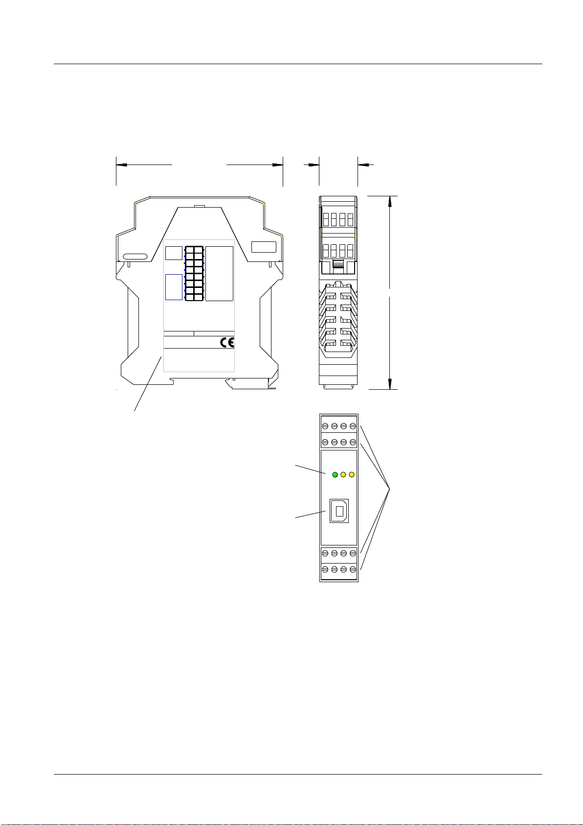
Klemmblöcke (steckbar)
Terminals (removable)
LEDs
USB
Interface
Typenschild und Anschlussbelegung
Type plate and terminal pin assignment
23,0000 mm99,0000 mm
114,0000 mm
2.2 Device description
W.E.ST.
Elektronik GmbH
Page 9 of 32 PID-131-U-2030 30.12.2015
Page 10

W.E.ST.
Elektronik GmbH
3 Use and application
3.1 Installation instructions
This module is designed for installation in a shielded EMC housing (control cabinet). All cables which
lead outside must be screened; complete screening is required. It is also necessary to avoid strong
electro-magnetic interference sources being installed nearby when using our open and closed loop
control modules.
Typical installation location: 24 V control signal area (close to PLC)
The devices must be arranged in the control cabinet so that the power section and the signal section
are separate from each other.
Experience shows that the installation place close to the PLC (24 V area) is most suitable. All digital and
analogue inputs and outputs are fitted with filters and surge absorbers in the device.
The module should be installed and wired in accordance with the documentation bearing in mind EMC
principles. If other consumers are operated with the same power supply, a star-shaped ground wiring
scheme is recommended. The following points must be observed when wiring:
The signal cables must be laid separately from power cables.
Analogue signal cables must be screened.
All other cables must be screened if there are powerful interference sources (frequency
converters, power contactors) and cable lengths > 3 m. Inexpensive SMD ferrites can be
used with high-frequency radiation.
The screening should be connected to PE (PE terminal) as close to the module as possible.
The local requirements for screening must be taken into account in all cases. The screening
should be connected to at both ends. Equipotential bonding must be provided where there
are differences between the connected electrical components.
If having longer lengths of cable (> 10 m) the diameters and screening measures should be
checked by specialists (e. g. for possible interference, noise sources and voltage drop).
Special care is required if using cables of over 40 m in length, and if necessary the
manufacturer should be consulted if necessary.
A low-resistance connection between PE and the mounting rail should be provided. Transient
interference is transmitted from the module directly to the mounting rail and from there to the local earth.
Power should be supplied by a regulated power supply unit (typically a PELV system complying with
IEC364-4-4, secure low voltage). The low internal resistance of regulated power supplies gives better
interference voltage dissipation, which improves the signal quality of high-resolution sensors in
particular. Switched inductances (relays and valve coils) which are connected to the same power supply
must always be provided with appropriate overvoltage protection directly at the coil.
Page 10 of 32 PID-131-U-2030 30.12.2015
Page 11

W.E.ST.
MINMAX
Input w
Input x
PID
Application interface
u
PLC
Sensor (position, pressure, velocity)
*4
*1
*2
*3
*5
Elektronik GmbH
3.2 Typical system structure
This minimal system consists of the following components:
(*1) Proportional valve (or control valve) with integrated electronics
(*2) Hydraulic cylinder
(*3) Sensor for the regulation of positions, pressures or speeds
(*4) Electronic module PID-131
(*5) Interface to PLC with analogue and digital signals
3.3 Method of operation
This control module can be used in a wide variety of applications, as powe , pressure and speed or velocity
control. The output signal suites any valves (with integrated electronics or external power amplifiers and power
plugs).
Due to the high stability of the PID controller, the use is particularly recommended where open loop control
would lead to poor reproducibility.
Typical use cases are pressure controlling fixed displacement pumps or remotely adjustable control pumps as
well as force/torque controls for cylinders and motors.
ENABLE: This digital input signal initializes the application. Error messages are deleted, the output is switched
on and the READY signal gets activated.
If the ENABLE input is deactivated the output gets switched off. Attention: Take care of the EOUT command.
Activating the RUN input starts the PID controller. Command and feedback input are evaluated now. The S0
input provides using an alternative second set of parameters if activated.
The function of input PIN5 depends on the parameterization. Either the ramp generator or the integrator can be
switched on and off with this input.
Page 11 of 32 PID-131-U-2030 30.12.2015
Page 12

Step
Task
Installation
Install the device in accordance with the circuit diagram. Ensure it is wired
correctly and that the signals are well shielded. The device must be installed in a
protective housing (control cabinet or similar).
Switching on for the first
time
Ensure that no unwanted movement is possible in the drive (e. g. switch off the
hydraulics). Connect an ammeter and check the current consumed by the device.
If it is higher than specified there is an error in the wiring. Switch the device off
immediately and check the wiring.
Setting up communication
Once the power input is correct the PC (notebook) should be connected to the
serial interface. Please see the WPC-300 program documentation for how to set
up communication.
Further commissioning and diagnosis are supported by the operating software.
Pre-parameterization
Now set up the following parameters (with reference to the system design and
circuit diagrams):
SENSOR SETTINGS and OUTPUT SIGNAL.
Parameterize specific settings for the control element (MIN, MAX and dither).
Pre-parameterization is necessary to minimize the risk of uncontrolled
movements.
Control signal
Check the control signal with a voltmeter. The control signal (PIN 15 to PIN16) is
in the range of ±10 V. In the current state it should show 0 V. Alternatively, if using
current signals, approximately 0 mA (PIN 15 to PIN 11) should flow.
Switching on the
hydraulics
The hydraulics can now be switched on. The module is not yet generating a
signal. Drives should be at a standstill or drift slightly (leave its position at a slow
speed).
Activating ENABLE
The module is set in operating state. If no error occures the operating state is
confirmed by the activated READY output and glowing green READY LED.
With the feedforward value the drive can be moved.
Activating START
Attention! Drives can now leave their position with maximum speed.
Take safety measures to prevent personal injury and damage. The control can
now be driven by the anlogue inputs.
Optimize controller
Now optimize the controller parameters according to your application and your
requirements.
3.4 Commissioning
W.E.ST.
Elektronik GmbH
Page 12 of 32 PID-131-U-2030 30.12.2015
Page 13

W.E.ST.
Connection
Supply
PIN 3
Power supply (see technical data)
PIN 4
0 V (GND) connection.
Connection
Analogue signals
PIN 11
GND
PIN 12
10 V Referenzspannungsausgang
PIN 13
Demand value (W), signal range 0… 10 V or 4… 20 mA, scalable
PIN 14
Actual value (X), signal range 0… 10 V or 4… 20 mA, scalable
PIN 15 / 16
Output control signal to the valve. Signal range +/- 10V, 0… 10V or 4… 20mA. Signal type and polarity are set with the parameter SIGNAL:U.
Connection
Digital inputs and outputs
PIN 8
Enable input:
General enabling of the application.
PIN 7
START (RUN) input:
Activates the controler and sets control signal.
PIN 6
S0 input:
Switching over between the parameter sets.
S0 = OFF : parameter set 1 is active
S0 = ON : parameter set 2 is active
PIN 5
RAMP/INTEG input:
Activates the ramp- or the integrator function. Function is chosen with the
parameter PIN5.
PIN 1
READY output:
ON: The module is enabled; there are no known errors.
OFF: Enable (PIN 8) is disabled or an error (current input or internal error) has
been detected.
PIN 2
STATUS output:
Monitoring of the control deviation depending on the CDWIN parameter, the status
output will be deactivated, if the control deviation is higher than the adjusted permitted range.
ON: control deviation is within the permitted range.
OFF: control deviation is out of the permitted range.
4 Technical description
4.1 Input and output signals
Elektronik GmbH
Page 13 of 32 PID-131-U-2030 30.12.2015
Page 14

LEDs
Description of the LED function
GREEN
Identical to the READY output.
OFF: No power supply or ENABLE is not activated
ON: System is ready for operation
Flashing: Error discovered
Only active when SENS = ON
YELLOW A
Identical to the STATUS output.
OFF: Control deviation is higher than CDWIN value.
ON: Control deviation is lower than CDWIN value.
GREEN +
YELLOW A+B
1. Chasing light (over all LEDs): The boot loader is active. No normal functions are
possible.
2. All LEDs flash shortly every 6 s: An internal data error was detected and corrected
automatically! The module still works regularly. To acknowledge the error the module
has to be cycle powered.
YELLOW A +
YELLOW B
Both yellow LEDs flash oppositely every 1 s: The non-volatile stored parameters are
inconsistent! To acknowledge the error, data has to be saved with the SAVE command or
the corresponding button in the WPC
4.2 LED definitions
W.E.ST.
Elektronik GmbH
Page 14 of 32 PID-131-U-2030 30.12.2015
Page 15

Commands:
SIGNAL:W
AIN:W
Input Scaling
PE via DIN-RAIL
15
16
11
1
2
Output: A
Output: B
8
5
Ready
Status
Enable
Run
24 V output
24 V output
USB Type B
Differential
Input
PID-131-U
7
13
14
0 V
0..10V
0 V
11
11
Feedback
4..20mA
Output Adaptation
Ramp / Integ
24 V input
24 V input
24 V input
U
Internal Power
3
4
0 V
Control program
24 V input
6
S0
Input Scaling
Commands:
SIGNAL:X
R_SENS:X
OFFSET:X
AIN:X
0..10V
4..20mA
0 V
Command
0 V
PID control
Commands:
- MIN:A and :B
- MAX:A and :B
- TRIGGER
- SIGNAL:U
DC
DC
24 V
0 V
PELV
Commands:
- LG (Language)
- MODE (Expert or Standard)
- TS
- SENS
- AINMODE
- PIN:5
- CDWIN
- EOUT (Error Mode)
Ramp Generator
X
WA
W
E
-
S0
C2:PIDD_T1FFI_LIM
I_ACT
PT1_P
PT1_T1
C1:PIDD_T1FFI_LIM
I_ACT
PT1_P
PT1_T1
RA1:UPDOWN
RA2:UPDOWN
Commands:
USB
Serial
56700 Bd
8N1
Commands:
4... 20 mA OUTPUT
PIN 15 = +
PIN 11 = GND
12
Reference voltage
output
4.3 Circuit diagram
W.E.ST.
Elektronik GmbH
Page 15 of 32 PID-131-U-2030 30.12.2015
Page 16

4.4 Typical wiring
+In PIN 13 or 14
PIN 11 (GND)
SPS / PLC 0... 10 V command input signal
+In PIN 13
-In PIN 11
AIN:W 2000 1600 2000 C ( für 0... 100%)
SPS / PLC 0... 10 V feedback input signal
+In PIN 14
In PIN 11 (GND)
PLC or sensor with 4... 20 mA (two wire connection)
z. B. 24 V
+In PIN 13 or 14
PIN 11 (GND)
AIN:W 2000 1600 2000 C ( für 0... 100%)
PLC or sensor with 4... 20 mA (three wire connection)
z. B. 24 V
Ventile (6 + PE Stecker) mit integrierter Elektronik
A : 24 V Versorgung
B : 0 V Versorgung
C : GND oder Enable
D : + Differenzeingang
E : - Differenzeingang
F : Diagnosesignal
PE -
PIN 15
PIN 16
PIN 12
8765
16151413
1211109
Shield
Analoger command
(0..10V or 4..20mA)
Power supply
tor
PLC
24V
0V
Ready
from
PLC
4321
Shield
Analoger feedback
(0..10V or 4..20mA)
0V
10 V Reference
voltage output
PE
PE
Enable
Run
S0
Ramp
CDWIN
To power amplifier /
valve +/- 10V.
Use differential input.
Using 4... 20mA PIN 15 to PIN 11.
0..10V or 4..20mA
0..10V
W.E.ST.
Elektronik GmbH
4.5 Connection examples
Page 16 of 32 PID-131-U-2030 30.12.2015
Page 17

Supply voltage (Ub)
Current requirement
External protection
[VDC]
[mA]
[A]
12… 30 (incl. ripple)
<100
1 medium time lag
Digital inputs
Input resistance
[V]
[V]
[kOhm]
logic 0: <2
logic 1: >10
25
Digital outputs
Maximum output current
[V]
[V]
[mA]
logic 0: <2
logic 1: max. Ub
50
Analogue inputs
Signal resolution
[V]
[mA]
[%]
0… 10; min. 25 kOhm
4… 20; 240 Ohm
0,003 incl. Oversampling
Analogue outputs
Voltage
Signal resolution
Current
Signal resolution
[V]
[mA]
[%]
[mA]
[%]
2 x 0… 10; differential output
5 (max. load)
0,006
4… 20; 390 Ohm maximum load
0,006
Controller sample time
[ms]
1 (variable from 0,5 … 3)
Serial interface
USB in RS 232C Emulation
(9600… 57600 Baud, 1 Stop bit,
no parity, Echo Mode)
Housing
Snap-on module to EN 50022
PA 6.6 polyamide
Flammability class V0 (UL94)
Weight
[kg]
0,170
Protection class
Temperature range
Storage temperature
Humidity
[°C]
[°C]
[%]
IP20
-20… 60
-20… 70
< 95 (non-condensing)
Connections
USB-B
4 x 4-pole terminal blocks
PE: via the DIN mounting rail
EMC
EN 61000-6-2: 8/2005
EN 61000-6-4: 6/2007 ; A1:2011
4.6 Technical data
W.E.ST.
Elektronik GmbH
Page 17 of 32 PID-131-U-2030 30.12.2015
Page 18

Group
Command
Default
Unit
Description
Basic parameters
LG
EN
-
Changing language help texts
MODE
STD
-
Parameter view
SENS
AUTO
-
Malfunction monitor
PIN:5
RAMP
-
Function of pin 5
CDWIN
200
0,01%
Size of the control deviation window
EOUT
0
0,01 %
Output signal if not ready
Input signal adaptation
Sensor scaling
SIGNAL:X
U0-10
Type of input
N_RANGE:X
100
%
Range of sensor in relation to working range
OFFSET:X
0
0,01%
Sensor offset
Command Input scaling
SIGNAL:W
U0-10
-
Type of input.
Ramp and PID control parameters
Parameter set 1
RA1:UP
RA1:DOWN
100
100
ms
ms
Command signal ramp times
C1:P
C1:I
C1:D
C1:D_T1
C1:FF
C1:I_LIM
C1:I_ACT
C1:PT1_P
C1:PT1_T1
50
4000
0
500
0
2500
2500
0
50
0,01 %
0,1 ms
0,1 ms
0,1 ms
0,01 %
0,01 %
0,01 %
0,01 %
0,1 ms
P gain
I gain
D gain
D gain filter
Feed forward
Integrator limitation
Integrator activation threshold
PT1 gain
PT1 time constant
Parameter set 2
RA2:UP
RA2:DOWN
100
100
ms
ms
Command signal ramp time
C2:P
C2:I
C2:D
C2:D_T1
C2:FF
C2:I_LIM
C2:I_ACT
C2:PT1_P
C2:PT1_T1
50
4000
0
500
0
2500
2500
0
50
0,01 %
0,1 ms
0,1 ms
0,1 ms
0,01 %
0,01 %
0,01 %
0,01 %
0,1 ms
P gain
I gain
D gain
D gain filter
Feed forward
Integrator limitation
Integrator activation threshold
PT1 gain
PT1 time constant
5 Parameters
5.1 Parameter overview
W.E.ST.
Elektronik GmbH
Page 18 of 32 PID-131-U-2030 30.12.2015
Page 19

W.E.ST.
Group
Command
Default
Unit
Description
Output signal adaptation
MIN:A
MIN:B
0
0
0,01 %
0,01 %
Dead band compensation
MAX:A
MAX:B
10000
10000
0,01 %
0,01 %
Output scaling
TRIGGER
200
0,01 %
Dead band compensation trigger point
SIGNAL:U
U+-10
-
Type of output signal and polarity
Special commands
Sample time
TS
10
0,1 ms
Sample time of the control loop
Scaling mode
AINMODE
EASY
-
Input scaling mode
AIN:X
AIN:W
A: 1000
B: 1000
C: 0
X: V
-
-
0,01 %
-
Free scaling of the analogue inputs. Gets activated when
AINMODE is switched over to MATH.
Elektronik GmbH
Page 19 of 32 PID-131-U-2030 30.12.2015
Page 20

W.E.ST.
Command
Parameters
Unit
Group
LG x
x= DE|EN
-
STD
Command
Parameters
Unit
Group
MODE x
x= STD|EXP
-
STD
Command
Parameters
Unit
Group
SENS x
x= ON|OFF|AUTO
-
STD
Elektronik GmbH
5.2 Basic parameters
LG (Changing the language)
Either German or English can be selected for the help texts.
CAUTION: After changing the language settings the ID button (SPEED BUTTON) in the menu bar
(WPC-300) must be pressed (module identification).
MODE (Switching between parameter groups)
This command changes the operating mode. Various commands (defined via STD/EXP) are blanked out in
Standard Mode. The commands in Expert Mode have a more significant influence on system behavior and
should accordingly be changed with care.
SENS (monitoring of the modul functions)
This command is used to activate/deactivate the monitoring functions (4… 20 mA inputs and internal failures) of
the module.
ON: All monitoring functions are active. Detected failures can be reset by deactivating the ENABLE input.
OFF: No monitoring function is active.
AUTO: Auto reset mode. All monitoring functions are active. If the failure does not exist anymore, the mod-
ule automatically resumes to work.
Normally the monitoring functions are always active because otherwise no errors are detectable via
the READY output. Deactivating is possible mainly for troubleshooting.
Page 20 of 32 PID-131-U-2030 30.12.2015
Page 21

W.E.ST.
Command
Parameters
Unit
Group
PIN5 x
x= RAMP|INTEG
-
STD
Command
Parameters
Unit
Group
CDWIN x
x= 0… 2000
0,01 %
STD
Command
Parameters
Unit
Group
EOUT x
x= -10000… 10000
0,01 %
EXP
2
Elektronik GmbH
PIN5 (Function of PIN 5)
With this command the function of PIN 5 can be defined.
RAMP: With input PIN 5 the ramp can be (de-)activated.
INTEG: With input PIN 5 the integrator can be (de-)activated. Ramp generator is active.
CDWIN (Size of the control deviation window)
This parameter is entered in 0.01 % of the setpoint .
The CDWIN command defines a monitoring rangewindow for which the CDWIN message is generated. The
monitoring window monitors the deviation between the setpoint and the actual feedback value. if the deviation is
within the CDWIN window, this is signaled via the status output and the CDWIN LED. The control process is not
influenced by this signal.
EOUT (Output signal if not ready)
Output value in case of a detected error or a missing ENABLE signal. A value (degree of valve opening) for use
in the event of a sensor error (or the module is disabled) can be defined here. This function can be used if, for
example, the drive shall move to one of the two end positions (at the specified speed) in case of a sensor error.
|EOUT| = 0 The output is switched off in the event of an error. This is normal behavior.
CAUTION! If the output signal is 4… 20 mA, the output is switched off when |EOUT| = 0. If a null
value = 4 mA is to be output in the event of an error, EOUT must be set to 12.
The output value defined here is stored permanently (independently of the parameter set). The
effects should be analyzed by the user for each application from the point of view of safety.
This is necessary if using valves without error detection for signals lower than 4 mA. If the valve has an error detection it
goes into a defined position after switching of the output.
Page 21 of 32 PID-131-U-2030 30.12.2015
Page 22

W.E.ST.
Command
Parameter
Unit
Group
SIGNAL:i x
i= W|X
x= OFF|U0-10|I4-20|
U10-0|I20-4
V|mA
EASY
Command
Parameter
Unit
Group
N_RANGE:X x
x= 1… 10000
%
EASY
Command
Parameter
Unit
Group
OFFSET:X x
x=-10000… 10000
0,01%
EASY
3
Elektronik GmbH
5.3 Input signal adaptation
SIGNAL (Type of input)
This command can be used to change the type of input signal (voltage or current) and to define the direction of
the signal. This command is available for all analogue inputs (W, X).
OFF= Deactivation of the input3.
N_RANGE:X (Nominal range of the sensor)
With this command, the measurement range of the sensor is defined. The format is a percentage figure in relation to the operating range of the system. Since this is a general PID controller, the working range of the system
is defined as 100%. Incorrect specifications lead to a corrupted system and the dependent parameters cannot
be calculated correctly.
N_RANGE normally should not be less than 100 %
OFFSET:X (Sensor offset)
With this command, the zero point of the sensor is set. The format is a percentage figure in relation to the operating range of the system. Since this is a general PID controller, the working range of the system is defined as
100%
The deactivation can be used to deactivate the velocity (speed) input PIN_9/10 (the VELO value is active).
Page 22 of 32 PID-131-U-2030 30.12.2015
Page 23

W.E.ST.
Command
Parameters
Unit
Group
RAp:i x
p= 1|2(Parameter set)
i= UP|DOWN
x= 1… 600000
ms
STD
t
Ausgang/Output A
A:UP
A:DOWN
Elektronik GmbH
Using the commands SIGNAL:X, N_RANGE:X and OFFSET:X
With these commands, the feedback sensor is scaled. Suppose you have a pressure control with the following
characteristics:
The system pressure is 350 bar
The pressure sensor has a 4-20mA current output
The nominal pressure of the sensor is 600bar (20mA at 600bar)
The sensor has an offset of 3bar (at 0bar real pressure 3bar are displayed)
To scale this sensor correctly the following settings should be made:
SIGNAL:X I4-20
N_RANGE:X 171% (for 600bar are 171% of 350bar )
OFFSET:X -85 ( because 3bar is representing 0.85 % of 350bar )
5.4 Ramp and PID control parameters
RA (Command signal ramp times)
Ramp function for the 1st and 2nd quadrant.
The ramp time is adjusted separately for rising and falling input signals.
Page 23 of 32 PID-131-U-2030 30.12.2015
Page 24

W.E.ST.
Command
Parameters
Unit
Group
Cp:i x
p= 1|2 (parameter set)
i= P|I|D|D_T1|FF|I_LIM|I_ACT|PT1_P|PT1_T1
:P x= 0… 10000
:I x= 0… 30000
:D x= 0… 1200
:D_T1 x= 0… 1000
:FF x= 0… 10000
:I_LIM x= 0… 10000
:I_ACT x= 0… 10000
:PT1_P x= 0… 10000
:PT1_T1 x= 5… 1000
0,01 %
0,1 ms
0,1 ms
0,1 ms
0,01 %
0,01 %
0,01 %
0,01 %
0,1 ms
STD
w Sollwertskalierung
Rampenfunktion
x Istwertskalierung
-
0.. 10 V
4.. 20 mA
C:PT1_P
C:PT1_T1
Druckregler
C:P P-Verstärkung
C:I I-Anteil
C:D D-Anteil
C:T1 D-Anteil Filter
C:FF Vorsteuerung
LIM:I Integratorbegrenzung
LIM:S Integratoraktivierungsschwelle
C:PT1_P PT1 Verstärkung
C:PT1_T1 PT1 Zeitkostante
0.. 10 V
4.. 20 mA
C:P
C:I LIM:ILIM:S
w
x
C:D
C:T1
-
C:SC
Elektronik GmbH
C (PID Control Settings)
The control function will be parameterized via these commands.
The P, I and D gain are similar to a standard PID controller. The D_T1 factor is a filter for the D-gain in order to
suppress high-frequency noise.
Via the FF value the command value is lead directly to the output. Because of that the controller only has to
compensate the control deviation. This causes a solid type of control and a dynamic triggering.
I_ACT controls the integrator function. To reduce pressure overshoots, an activation point for the integrator can
be programmed via the LIM:S value. The integrator is activated if the actual pressure is higher than the programmed threshold.
I_LIM limits the working range of the integrator, so that the controller can quickly react to the process without
any major overshoots. If the value is too small, it may have the effect that the non-linearity of the valve cannot
be fully compensated.
The commands PT1_P and PT1_T1 set up an additional PT1 controller component parallel to the P component.
The low pass filtered P component can often be operated at higher gains than the direct P component. The sta-
bility is improved by the T1 value.
Page 24 of 32 PID-131-U-2030 30.12.2015
Page 25

W.E.ST.
Command
Parameters
Unit
Group
MIN:I x
MAX:I x
TRIGGER x
i= A|B
x= 0… 6000
x= 3000… 10000
x= 0… 4000
-
0,01 %
0,01 %
0,01 %
STD
MAX:A
MIN:A
MIN:B
MAX:B
Input
Output
TRIGGER
Elektronik GmbH
5.5 Output signal adaptation
MIN (Deadband compensation)
MAX (Output scaling)
TRIGGER (Deadband compensation trigger point)
With this command, the output signal is adjusted to the valve characteristics. With the MAX value the output signal (the maximum valve current) will be defined. With the MIN value the overlap (dead band of the valve) will be
compensated. Via the TRIGGER the activation point of the MIN function is set and so a non-sensitive range
around the zero-point can be specified.
ATTENTION: If the MIN value is set too high, it influences the minimal pressure, which cannot
be adjusted any longer. In extreme case, this causes to an oscillating at small input values.
Page 25 of 32 PID-131-U-2030 30.12.2015
Page 26

W.E.ST.
Command
Parameters
Unit
Group
SIGNAL:U x
x= U+-10|I4-12-20|
U-+10|I20-12-4|
U0-10|I4-20|
U10-0|I20-4
V|mA
STD
Elektronik GmbH
SIGNAL:U (Output type and polarity)
This command defines the type of the output signal (current / voltage) and its polarity.
You can also choose between differential and unipolar output types.
With differential outputs, the output voltage lies between terminals 15 and 16, single ended Output lies on termi-
nal 15 with reference to terminal 11.
Differential voltage
o +-10V
o -+10V
Single ended voltage
o 0-10V
o 10-0V
Single ended current with zero point at 12mA
o 4-12-20mA
o 20-12-4mA
Single ended current with zero point at 4mA
o 4-20mA
o 20-4mA
An output current of less than 4 mA indicates that an error occurred or the module is not enabled.
It is important to ensure that the connected valve closes at currents below 4mA. (If this is not the
case, the EOUT command should be used to generate a defined output signal)
Page 26 of 32 PID-131-U-2030 30.12.2015
Page 27

W.E.ST.
Command
Parameters
Unit
Group
TS x
x= 5… 30
0,1 ms
TERMINAL
Command
Parameters
Unit
Group
AINMODE x
x= EASY|MATH
-
TERMINAL
Elektronik GmbH
5.6 Special commands
TS (Sample time)
The control dynamics can be influenced with the sample time. Changes should only be made by persons who
have sufficient knowledge of the dynamic system behavior.
CAUTION! After changing this value all time-dependent parameters must be checked and reset if
necessary.
AINMODE (Input scaling mode)
The command AINMODE is used to choose the input scaling method.
In the EASY mode (the default mode) the user may choose via the SIGNAL command from a variety of stand-
ard input signal types and polarities. The MATH mode, which is compatible to our older modules may be used to
freely scale inputs with the AIN command.
Attention: This command does not show up in the parameter list in WPC. It has to be entered manually in the terminal window. After any change of AINMODE, module default data should be applied
(by pressing the corresponding button in WPC300)
Page 27 of 32 PID-131-U-2030 30.12.2015
Page 28

W.E.ST.
Command
Parameters
Unit
Group
AIN:i
a
b
c
x
i= W|X
a= -10000… 10000
b= -10000… 10000
c= -500… 10000
x= V|C
-
-
0.01%
-
MATH
)( cInput
b
a
Output
Command
Input
signal
Description
AIN:x 1000 1000 0 V
0… 10 V
Range: 0… 100 %
AIN:x 10 8 1000 V OR
AIN:x 1000 800 1000 V
1… 9 V
Range: 0… 100 %; 1 V = 1000 used for the offset and
gained by 10 / 8 (10 V divided by 8 V (9 V -1 V))
AIN:x 10 4 500 V OR
AIN:x 1000 400 500 V
0,5… 4,5 V
Range: 0… 100 %; 0,5 V = 500 used for the offset and
gained by 10 / 4 (10 V divided by 4 V (4,5 V -0,5 V))
AIN:x 20 16 2000 C OR
AIN:x 2000 1600 2000 C OR
AIN:x 1250 1000 2000 C
4… 20 mA
Range: 0… 100 %
The offset will be compensated on 20 % (4 mA) and the
signal (16 mA = 20 mA – 4 mA) will be gained to 100 %
(20 mA).
Each of this parameterization for 4… 20 mA is setting the
range to 0… 100 %.
Elektronik GmbH
AIN (Free analogue input scaling)
This command offers a method to individualy scale an input. The following linear equation is used for the
scaling.
The “C” value is the offset (e.g. to compensate the 4 mA in case of a 4… 20 mA input signal).
The variables A and B are defining the gain factor with which the signal range is scaled up to 100 % (e.g. 1.25 if
using 4… 20mA input signal, defined in default current settings by A = 1250 and B = 1000). The internal shunt
for the current measuring is activated with switching the X value.
The gain factor is calculated by setting the usable range (A) in relation to the real used range (B) of the input
signal. Usable are 0… 20mA, means (A) has the value 20. Really used are 4… 20mA, means (B) has a value of
16 (20-4). Not used are 0… 4mA. In a range of 20mA this is an offset of 20%, means a value of 2000 for (C).
Last but not least (X) has to be set to C choosing current signal.
In this case AIN command would look like this:
AIN:I 20 16 2000 C or AIN:I 1250 1000 2000 C
Typical settings (examples):
Page 28 of 32 PID-131-U-2030 30.12.2015
Page 29

W.E.ST.
Command
Parameters
Unit
W
WA
X
E
C
U
Command input signal
Command value
Actual value
Control deviation
Controler output
Output control signal
%
%
%
%
%
%
Elektronik GmbH
5.7 PROCESS DATA (Monitoring)
The process data are the variables which can be observed continuously on the monitor or on the oscilloscope.
Page 29 of 32 PID-131-U-2030 30.12.2015
Page 30

W.E.ST.
Source
Fault
Characteristic
Command signal PIN 13
4... 20 mA
Out of range.
The output will be switched off.
Feedback signal PIN 14
4… 20 mA
Out of range.
The output will be switched off.
EEPROM
(at switching on)
Data error
The output is deactivated.
The module can be activated by
saving parameters again.
FAULT
CAUSE / SOLUTION
ENABLE is active, the
module does not
respond, and the
READY LED is off.
There is presumably no power supply or the ENABLE signal (PIN 8) is not present.
If there is no power supply there is also no communication via our operating
program. If a connection has been made to the WPC-300, then a power supply is
also available.
ENABLE is active, the
READY LED is flashing.
The flashing READY LED signals that a fault is been detected by the module. The
fault could be:
A broken cable or no signal at the input (PIN 13 oder 14), if 4…20 mA signals are
parameterized.
Internal data error: press the command/SAVE button to delete the data error. The
system reloads the DEFAULT data.
With the WPC-300 operating program the fault can be localized directly via the
monitor.
ENABLE and RUN are
active; the READY LED
is on, the system moves
to an end position.
The control circuit polarity is incorrect. The polarity can be changed with the
SIGNAL:U command or by reversing the connections to PIN 15 and PIN 16.
Elektronik GmbH
6 Appendix
6.1 Failure monitoring
Following possible error sources are monitored continuously when SENS = ON / AUTO:
CAUTION: Take care of the EOUT command. Changes will influense the behaviour.
6.2 Troubleshooting
It is assumed that the device is in an operable state and there is communication between the module and the
WPC-300. Furthermore, the valve control parameterization has been set with the assistance of the valve data
sheets. The RC in monitor mode can be used to analyze faults.
CAUTION: All safety aspects must be thoroughly checked when working with the RC (Remote
Control) mode. In this mode the module is controlled directly and the machine control cannot
influence the module.
Page 30 of 32 PID-131-U-2030 30.12.2015
Page 31

W.E.ST.
Elektronik GmbH
6.3 Description of the command structure
The command structure:
[nnnn:i x] or
[nnnn x]
Meaning:
nnnn - used for an arbitrary command name
nnnn: - used for an arbitrary command name, expandable by an index.
Indexed commands are indicated by the sign “:”
i or I - a dummy is for the index. E. g. an index can be „A“ or „B“, depending on the direction.
x - parameter value, in case of special commands more than one parameter are possible.
Examples:
MIN:A 2000 nnnn = “MIN”, i = “A” and x = “2000”
OFFSET 50 nnnn = „OFFSET“ and x = „50“
C:IC 2000 nnnn = “C”, i = “IC” and x = “2000”
Page 31 of 32 PID-131-U-2030 30.12.2015
Page 32

7 Notes
W.E.ST.
Elektronik GmbH
Page 32 of 32 PID-131-U-2030 30.12.2015
 Loading...