

W.E.ST. MDR-133-U, MDR-133-P Technical Documentation Manual
Technical Documentation
MDR-133-U
MDR-133-P
Pressure control module

CONTENTS
1 General Information.......................................................................................................................................... 4
1.1 Order number ........................................................................................................................................... 4
1.2 Scope of supply ........................................................................................................................................ 4
1.3 Accessories .............................................................................................................................................. 4
1.4 Symbols used ........................................................................................................................................... 5
1.5 Using this documentation .......................................................................................................................... 5
1.6 Legal notice .............................................................................................................................................. 5
1.7 Safety instructions .................................................................................................................................... 6
2 Characteristics ................................................................................................................................................. 7
2.1 Compatibility............................................................................................................................................. 8
2.2 Device description .................................................................................................................................... 9
3 Use and application ........................................................................................................................................ 10
3.1 Installation instructions ............................................................................................................................ 10
3.2 Typical system structure ......................................................................................................................... 11
3.3 Method of operation ................................................................................................................................ 11
3.4 Commissioning ....................................................................................................................................... 12
4 Technical description ...................................................................................................................................... 13
4.1 Input and output signals .......................................................................................................................... 13
4.2 LED definitions ....................................................................................................................................... 14
4.3 Circuit diagram ....................................................................................................................................... 15
4.4 Typical wiring ......................................................................................................................................... 16
4.5 Connection examples ............................................................................................................................. 16
4.6 Technical data ........................................................................................................................................ 17
5 Parameters .................................................................................................................................................... 18
5.1 Parameter overview ................................................................................................................................ 18
5.2 Configuration .......................................................................................................................................... 19
5.2.1 LG (Changing the language) ........................................................................................................... 19
5.2.2 MODE (Switching between parameter groups) ................................................................................ 19
5.2.3 SENS (Malfunction monitoring) ................................ ....................................................................... 19
5.2.4 CDWIN (Control deviation window) ................................................................................................. 20
5.2.5 EOUT (Output signal: READY = OFF) ............................................................................................. 20
5.3 Input signal adaptation ............................................................................................................................ 21
5.3.1 SYS_RANGE (Sytem pressure) ...................................................................................................... 21
5.3.2 SIGNAL (Type of input) .................................................................................................................. 21
5.3.3 N_RANGE:X (Nominal pressure of the sensor) ............................................................................... 21
5.3.4 OFFSET:X (Sensor offset) .............................................................................................................. 22
5.3.5 Using of the commands SYS_RANGE, N_RANGE:X and OFFSET:X .............................................. 22
5.4 Ramp function ................................................................................................ ........................................ 23
5.4.1 RA (Command signal ramp times) .................................................................................................. 23
5.5 Closed loop control parameters ............................................................................................................... 24
5.5.1 PID controller ................................................................................................................................. 24
5.5.2 Integrator control function ............................................................................................................... 25
5.6 Output signal adaptation ......................................................................................................................... 26
5.6.1 MIN (Deadband compensation) ...................................................................................................... 26
5.6.2 MAX (Output scaling) ..................................................................................................................... 26
5.6.3 TRIGGER (Response threshold for the MIN parameter) .................................................................. 26
5.6.4 SIGNAL:U (Type and polarity of the output signal) ........................................................................... 27
5.7 Special commands ................................................................................................................................. 28
5.7.1 TS (Sample time) ........................................................................................................................... 28
5.7.2 AINMODE (Input scaling mode) ...................................................................................................... 28
Page 2 of 42 MDR-133-*-2030 29.08.2019

5.7.3 AIN (Analogue input scaling) ........................................................................................................... 28
5.8 PROCESS DATA (Monitoring) ................................................................................................................. 29
6 Appendix ........................................................................................................................................................ 30
6.1 Failure monitoring ................................................................................................ ................................... 30
6.2 Troubleshooting ...................................................................................................................................... 31
6.3 Description of the command structure ...................................................................................................... 33
7 ADDITIONAL INFORMATION: Power output stage ......................................................................................... 34
7.1 General function ..................................................................................................................................... 34
7.2 Device description ................................................................................................................................... 35
7.3 Inputs and outputs .................................................................................................................................. 36
7.4 Circuit diagram........................................................................................................................................ 36
7.5 Typical wiring .......................................................................................................................................... 37
7.6 Technical data ........................................................................................................................................ 37
7.7 Parameters ............................................................................................................................................. 39
7.7.1 Parameter overview ........................................................................................................................ 39
7.8 Changed parameters from U-version ....................................................................................................... 39
7.8.1 SIGNAL:U (Polarity of the output signal) .......................................................................................... 39
7.8.2 SIGNAL:M (Type of the monitor output signal) ................................................................................. 39
7.9 Parameter description of the power stage ................................................................................................ 40
7.9.1 CURRENT (Rated output current) ................................................................................................... 40
7.9.2 DFREQ (Dither frequency) .............................................................................................................. 40
7.9.3 DAMPL (Dither amplitude) .............................................................................................................. 40
7.9.4 PWM (PWM Frequenz) ................................................................................................................... 41
7.9.5 ACC (Current loop ato adjustment ) ................................................................................................. 41
7.9.6 PPWM (Solenoid current controller P element) ................................................................................ 41
7.9.7 IPWM (Solenoid current controller I element) ................................................................................... 41
8 Notes ............................................................................................................................................................. 42
Page 3 of 42 MDR-133-*-2030 29.08.2019

1
2
1 General Information
1.1 Order number
MDR-133-U1-20302 - with programmable output (0… 10 V or 4… 20 mA) and analogue sensor interface
MDR-133-P-2030 - with additional power output stage up to 2,6 A (see additional information)
Alternative Products
MDR-137-P-2030 - with integrated power stage up to 2,6 A and analogue interface
1.2 Scope of supply
The scope of supply includes the module plus the terminal blocks which are part of the housing.
The Profibus plug, interface cables and further parts which may be required should be ordered separately.
This documentation can be downloaded as a PDF file from www.w-e-st.de.
1.3 Accessories
WPC-300 - Start-Up-Tool (downloadable from our homepage – products/software)
Compared with older versions (ordering code A for voltages output and I for current output) the code U (universal) is
used for programmable outputs.
The number of the version consists of the hardware version (first two digits) and the software version (last two digits).
Because of the development of the products these numbers can vary. They are not strictly necessary for the order. We will
always deliver the newest version.
Page 4 of 42 MDR-133-*-2030 29.08.2019

1.4 Symbols used
General information
Safety-related information
1.5 Using this documentation
Structure of the documentation:
The standard product is descibed up to chapter 6. The extensions like POWER STAGE or SSI-INTERFACE
are described in the chapters ADDITIONAL INFORMATION.
1.6 Legal notice
W.E.St.
Gewerbering 31
D-41372 Niederkrüchten
Tel.: +49 (0)2163 577355-0
Fax.: +49 (0)2163 577355-11
Home page: www.w-e-st.de or www.west-electronics.com
EMAIL: info@w-e-st.de
Date: 29.08.2019
The data and characteristics described herein serve only to describe the product. The user is required to
evaluate this data and to check suitability for the particular application. General suitability cannot be inferred
from this document. We reserve the right to make technical modifications due to further development of the
product described in this manual. The technical information and dimensions are non-binding. No claims may
be made based on them.
This document is protected by copyright.
Elektronik GmbH
Page 5 of 42 MDR-133-*-2030 29.08.2019
1.7 Safety instructions
Please read this document and the safety instructions carefully. This document will help to define the product
area of application and to put it into operation. Additional documents (WPC-300 for the start-up software) and
knowledge of the application should be taken into account or be available.
General regulations and laws (depending on the country: e. g. accident prevention and environmental
protection) must be complied with.
These modules are designed for hydraulic applications in open or closed-loop control circuits.
Uncontrolled movements can be caused by device defects (in the hydraulic module or the
components), application errors and electrical faults. Work on the drive or the electronics must
only be carried out whilst the equipment is switched off and not under pressure.
This handbook describes the functions and the electrical connections for this electronic
assembly. All technical documents which pertain to the system must be complied with when
commissioning.
This device may only be connected and put into operation by trained specialist staff. The
instruction manual must be read with care. The installation instructions and the commissioning
instructions must be followed. Guarantee and liability claims are invalid if the instructions are
not complied with and/or in case of incorrect installation or inappropriate use.
CAUTION!
All electronic modules are manufactured to a high quality. Malfunctions due to the failure of
components cannot, however, be excluded. Despite extensive testing the same also applies
for the software. If these devices are deployed in safety-relevant applications, suitable external
measures must be taken to guarantee the necessary safety. The same applies for faults which
affect safety. No liability can be assumed for possible damage.
Further instructions
The module may only be operated in compliance with the national EMC regulations. It is
the user’s responsibility to adhere to these regulations.
The device is only intended for use in the commercial sector.
When not in use the module must be protected from the effects of the weather,
contamination and mechanical damage.
The module may not be used in an explosive environment.
To ensure adequate cooling the ventilation slots must not be covered.
The device must be disposed of in accordance with national statutory provisions.
Page 6 of 42 MDR-133-*-2030 29.08.2019

2 Characteristics
This module was developed for controlling of pressure and force in hydraulic systems. The controller structure
is optimized for pressure closed-loop control systems with typical pressure valves.
The controller works in a bypass control function, where the input signal is linked directly to the control output
(pressure valve) and the PID compensator has to control the linearity deviations only. In many cases the optimization without further test equipment (only a pressure sensor is needed) can be carried out.
The output signal is available as 0…10 V or 4… 20 mA signal for the direct connection of valves with inte-
grated electronics. Also external amplifiers and power plugs can be used.
Alternatively, the controller (P-version) is available with an integrated power output stage (see additional
information: POWER OUTPUT STAGE). The advantage of the integrated power output stage is founded in the
integrated control behavior without additional dead times. This allows higher dynamics and higher stability
respectively.
The start-up procedure is supported by our software tool WPC-300 (free download from our homepage).
Typical applications: pressure control with pressure limitation valves and/or pressure reducing valves.
Features
Analogue pressure command and actual values
Special pressure control concept for pressure reducing and relief valves
Optimized controller for pressure closed loop control
Integrated functions to prevent pressure overshoots
Simple optimizing of the controller
Ramps for pressure loading and unloading
Simple and application orientated parameter settings
Standard USB interface
Fault diagnosis and extended function checking
Simplified parameterization with WPC-300 software
Optional with power output stage (P version)
Page 7 of 42 MDR-133-*-2030 29.08.2019

2.1 Compatibility
As a result of further developments some smaller changes have to be taken in consideration.
Functionality:
1. Downward compatible to the older modules.
2. 100 % wiring compatible.
3. Baud rate: The default baud rate has changed from 9600 baud to 57600 baud. This is adaptable in
WPC-300: OPTIONS/SETTINGS/INTERFACE.
FIXBAUDRATE = 57600 and/or AUTO BAUDRATE DETECTION = 57600
4. Technical enhancements:
a. Programmable analogue output: only one version (U instead A and I) is necessary
b. Optional: Start-up support
Parameterization:
1. Standardizing of parameter names
2. Simplified and intuitive parameterization of the analogue inputs and sensors
3. Compatibility mode of the input scaling (AINMODE), if necessary
4. Adaptation of the output signal (current or voltages) and the polarity with the command SIGNAL:U
(the POL commando is removed)
5. Adaptation of the monitoring output signals (current or voltages) with the command SIGNAL:M
(only available in P-version)
Page 8 of 42 MDR-133-*-2030 29.08.2019
V:
ID:
Add.:Date:
Made in Germany
W.E.ST.
Ready
1 2 3 4
5 6 7 8
9 10 11 12
14 15 1613
D-41372 Niederkrüchten
Homepage: http://www.w-e-st.de
W.E.ST.
Elektronik
131415
9
10
11
12
16
A B
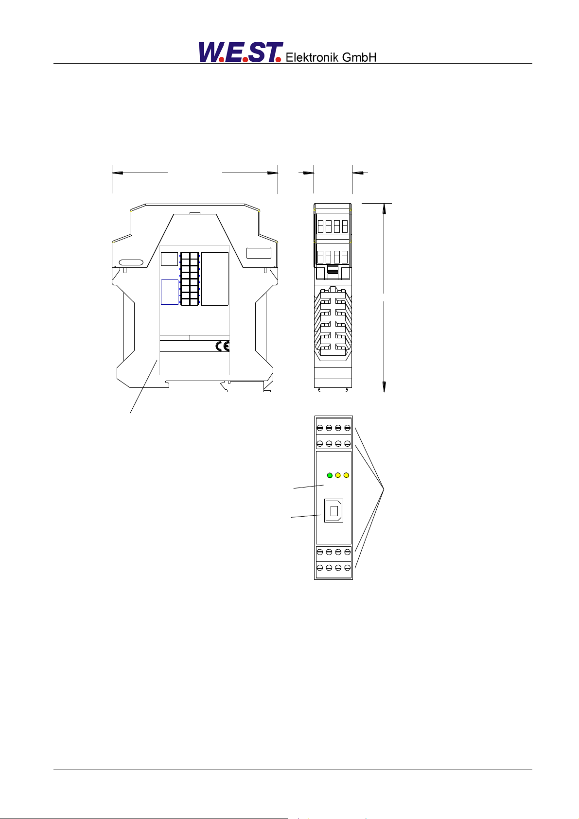
Klemmblöcke (steckbar)
Terminals (removable)
LEDs
USB-Interface
Typenschild und Anschlussbelegung
Type plate and terminal pin assignment
23,0000 mm99,0000 mm
114,0000 mm
2.2 Device description
Standard module – for the P-Version look at point 7.2
Page 9 of 42 MDR-133-*-2030 29.08.2019

3 Use and application
3.1 Installation instructions
This module is designed for installation in a shielded EMC housing (control cabinet). All cables which
lead outside must be screened; complete screening is required. It is also necessary to avoid strong
electro-magnetic interference sources being installed nearby when using our open and closed loop
control modules.
Typical installation location: 24 V control signal area (close to PLC)
The devices must be arranged in the control cabinet so that the power section and the signal section
are separate from each other.
Experience shows that the installation place close to the PLC (24 V area) is most suitable. All digital
and analogue inputs and outputs are fitted with filters and surge absorbers in the device.
The module should be installed and wired in accordance with the documentation bearing in mind EMC
principles. If other consumers are operated with the same power supply, a star-shaped ground wiring
scheme is recommended. The following points must be observed when wiring:
The signal cables must be laid separately from power cables.
Analogue signal cables must be screened.
All other cables must be screened if there are powerful interference sources (frequency
converters, power contactors) and cable lengths > 3 m. Inexpensive SMD ferrites can be
used with high-frequency radiation.
The screening should be connected to PE (PE terminal) as close to the module as
possible. The local requirements for screening must be taken into account in all cases. The
screening should be connected to at both ends. Equipotential bonding must be provided
where there are differences between the connected electrical components.
If having longer lengths of cable (> 10 m), the diameters and screening measures should
be checked by specialists (e. g. for possible interference, noise sources and voltage drop).
Special care is required if using cables of over 40 m in length, and if necessary the
manufacturer should be consulted if necessary.
A low-resistance connection between PE and the mounting rail should be provided. Transient
interference is transmitted from the module directly to the mounting rail and from there to the local
earth.
Power should be supplied by a regulated power supply unit (typically a PELV system complying with
IEC364-4-4, secure low voltage). The low internal resistance of regulated power supplies gives better
interference voltage dissipation, which improves the signal quality of high-resolution sensors in
particular. Switched inductances (relays and valve coils) which are connected to the same power
supply must always be provided with appropriate overvoltage protection directly at the coil.
Page 10 of 42 MDR-133-*-2030 29.08.2019
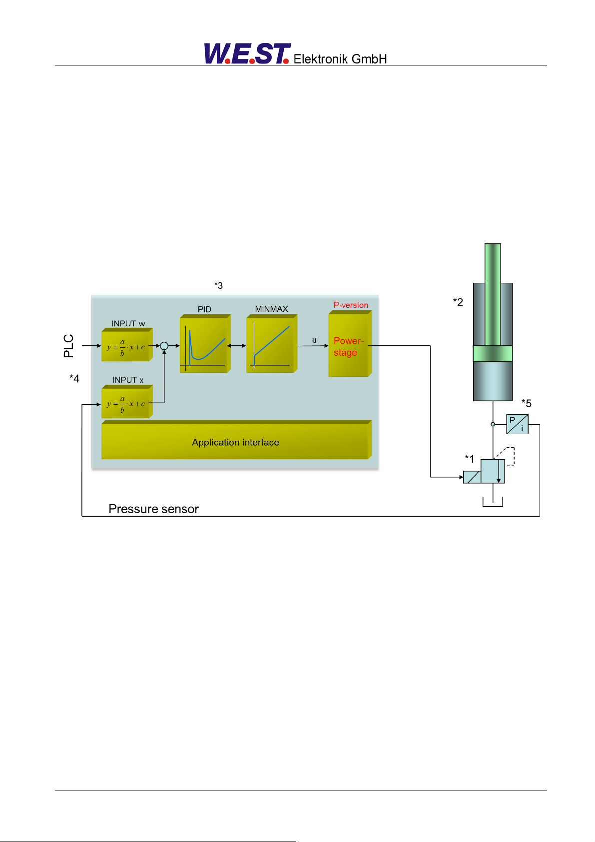
3.2 Typical system structure
This minimal system consists of the following components:
(*1) Pressure relieve valve (alternative: pressure controlled servo pump)
(*2) Cylinder / actuator
(*3) MDR-133 pressure controller
(*4) Interface to PLC
(*5) Pressure or force sensor
3.3 Method of operation
This module is useful for pressure control in very different applications.The output signal controls various
pressure valves (with integrated electronics or external power amplifier as well as with power plugs).
Optionally the device can control valve coils directly via integrated power stage (P-version). The advantages
are an easier handling, lower costs and less spares inventory.
Because of the very high stability of the pressure control structure this module is recommended where open
loop applications are not sufficient concerning the accuracy. Pressure controls with constant pumps or remote
controllable servo pumps and for force and torque controls with cylinders and motor drives are typical applications.
By means of an enable signal the output gets activated and can be controlled by the command value. The operational readiness is reported via a ready signal. With setting the start signal, the feedback value will be read
in and the PID controller starts calculating and generating the output signal depending on the control deviation
and the parameterization. The ramp function for the command signal can be switched on and off with this corresponding digital input. The type of the output signal is selectable (SIGNAL:U).
Page 11 of 42 MDR-133-*-2030 29.08.2019

Step
Task
Installation
Install the device in accordance with the circuit diagram. Ensure it is wired correctly and that the signals are well shielded. The device must be installed in a
protective housing (control cabinet or similar).
Switching on for the first time
Ensure that no unwanted movement is possible in the drive (e. g. switch off the
hydraulics). Connect an ammeter and check the current consumed by the device. If it is higher than specified, there is an error in the wiring. Switch the device off immediately and check the wiring.
Setting up communication
Once the power input is correct the PC (notebook) should be connected to the
serial interface. Please see the WPC-300 program documentation for how to
set up communication.
Further commissioning and diagnosis are supported by the operating software.
Pre-parameterization
Parameterize now (with the help of the system redundancy and the connection
diagram) the following parameters:
The SYSTEM PRESSURE, the SENSOR SETTINGS, the OUTPUT SIGNAL
as well as the COMMAND SIGNAL and approximately the PID CONTROLLER.
Pre-parameterization is necessary to minimize the risk of an unintentional
movement / pressure.
Control signal
Check the control signal with a voltmeter. The control signal lies in the range of
0… 10 V. In the current state it should be 0 V. Alternatively, if current signals
are used, approx. 0 mA should flow.
Switching on the hydraulics
The hydraulics can now be switched on. The module is not yet generating a
signal. Drives should be at a standstill or drift slightly (leave its position at a
slow speed).
Activating ENABLE
CAUTION! Drives can now leave their position and move to an end position at
full speed. Take safety measures to prevent personal injury and damage.
The device can now be used in open loop control by the command input.
Activating START
This digital signal activates the PID controller. The feedback value will be read
in and the output signal gets calculated.
Controller optimization
Now optimize the parameterization of the controller according to your application and your requirements.
3.4 Commissioning
Page 12 of 42 MDR-133-*-2030 29.08.2019
Connection
Supply
PIN 3
Power supply (see technical data)
PIN 4
0 V (GND) connection
Connection
Analogue signals
PIN 11
0 V (GND) connection
PIN 12
Reference output voltage
PIN 13
Command value input (W), signal range 0… 10 V or 4… 20 mA, scalable
PIN 14
Actual value input (X), signal range 0… 10 V or 4… 20 mA, scalable
PIN 15 / 12
Output signal to the valve
Type and polarity of signal are selectable by SIGNAL:U
Connection
Digital inputs and outputs
PIN 1
READY output:
ON: The module is enabled; there are no discernable errors.
OFF: Enable (PIN 8) is disabled or an error (sensor or internal error) has been detected.
PIN 2
STATUS output:
ON: The control deviation is within the defined range (CDWIN).
OFF: The control deviation is outside the defined range (CDWIN).
PIN 5
RAMP input:
Activates the ramp function for the command value.
PIN 7
RUN input:
Activates the pressure controller.
PIN 8
ENABLE input:
This digital input signal initializes the application. Error messages are deleted. The analogue
output and the READY signal will be activated.
4 Technical description
4.1 Input and output signals
Page 13 of 42 MDR-133-*-2030 29.08.2019
 Loading...