

Page 1
PROG
1
-DIN
4
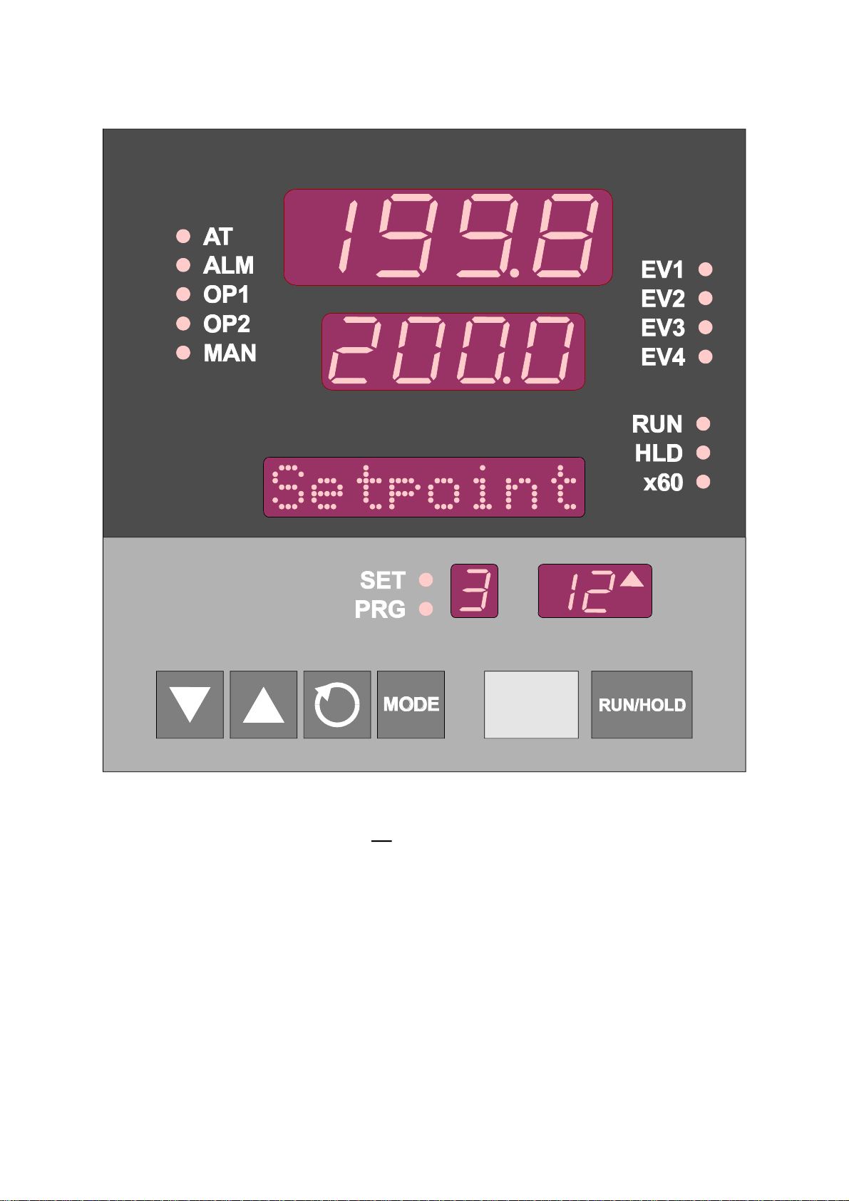
SETPOINT PROGRAMMER
Site Manual
59216-1
Page 2

PREFACE
This manual is intended for use in support of installation, commissioning and
configuration of the
1
-DIN Setpoint Programmer. For information on the day-to-day
4
operation, refer to the associated Operator's manual (see below).
Associated Documents
Title Part No.
1
-DIN Setpoint Programmer Operator's Manual 59215
4
The procedures described in this manual must be undertaken only by
technically-competent and authorised servicing personnel.
Page 3

59216
Contents
1 INTRODUCTION 1-1
2 INSTALLATION 2-1
2.1 UNPACKING PROCEDURE ....................... 2-1
2.2 PANEL-MOUNTING THE SETPOINT PROGRAMMER ............ 2-1
2.3 CONNECTIONS AND WIRING ..................... 2-4
2.3.1 Mains (Line) In put ......................... 2-5
2.3.2 24V (Nomi nal) AC/DC Sup ply ................... 2-5
2.3.3 Ther mo cou ple In put ........................ 2-7
2.3.4 RTD In puts ............................. 2-7
2.3.5 Lin ear In puts............................2-7
2.3.6 Digi tal In puts............................2-7
2.3.7 Re lay Out puts ...........................2-8
2.3.8 SSR Drive Out puts..........................2-9
2.3.9 DC Out puts............................. 2-9
2.3.10 Event Out puts ...........................2-9
2.3.11 RS485 Se rial Com mu ni ca tions Link.................2-9
3 INTERNAL LINKS AND SWITCHES 3-1
3.1 REMOVING THE SETPOINT PROGRAMMER FROM ITS HOUSING ..... 3-1
3.2 REMOVING/REPLACING THE OUTPUT 2/OUTPUT 3 OPTION PCBs..... 3-3
3.3 REMOVING/REPLACING THE RS485 COMMUNICATIONS OPTION PCB . 3-3
3.4 INSTALLING/REMOVING THE DIGITAL INPUT OPTION PCB ........ 3-4
3.5 INSTALLING/REMOVING THE EVENT OUTPUT OPTION PCB ........ 3-5
3.6 REPLACING THE SETPOINT PROGRAMMER IN ITS HOUSING ....... 3-5
3.7 SELECTION OF INPUT TYPE ....................... 3-6
3.8 SELECTION OF PRIMARY OUTPUT (OUTPUT 1) TYPE............ 3-7
3.9 OUTPUT 2 TYPE/OUTPUT 3 TYPE ..................... 3-8
4 CONFIGURATION MODE 4-1
4.1 ENTRY INTO CONFIGURATION MODE .................. 4-1
59216-FM (iii)
Page 4

59216
4.2 HARDWARE DEFINITION CODE..................... 4-1
4.3 CONFIGURATION MODE PARAMETERS ................. 4-4
4.4 ALARM INHIBIT FACILITY ........................4-7
4.5 EXIT FROM CONFIGURATION MODE .................. 4-7
5 SERIAL COMMUNICATIONS - ASCII PROTOCOL 5-1
5.1 RS485 CONNECTIONS.........................5-1
5.2 COMMUNICATIONS ENABLE/DISABLE .................. 5-1
5.3 SELECTION OF COMMUNICATIONS ADDRESS ............. 5-1
5.4 ASCII COMMUNICATIONS PROTOCOL ................. 5-1
5.4.1 Type 1 Mes sage ..........................5-3
5.4.2 Type 2 Mes sage ..........................5-3
5.4.3 Type 3 Mes sage ..........................5-4
5.4.4 Type 4 Mes sage ..........................5-4
5.5 PROGRAMMER PARAMETERS (Start of Message character = R)....5-5
5.6 PROGRAMMER COMMANDS ..................... 5-8
5.7 PROGRAMMER STATUS 1........................ 5-8
5.8 CURRENT SEGMENT EVENT STATUS ................... 5-9
5.9 POWER FAIL RECOVERY ........................ 5-9
5.10 PROGRAM/SEGMENT DEFINITIONS ................... 5-9
5.11 PROGRAM SCAN TABLE........................ 5-10
5.12 SEGMENT MODE........................... 5-10
5.13 PROGRAMMER STATUS 2 .......................5-11
5.14 USER TAG NAMES........................... 5-11
5.15 CONTROLLER PARAMETERS (Start of Message character = L) .... 5-12
5.16 CONTROLLER SCAN TABLE ...................... 5-16
5.17 ERROR RESPONSE .......................... 5-16
5.18 MASTER COMMUNICATIONS MODE.................. 5-16
6 MODBUS RTU SERIAL COMMUNICATIONS 6-1
6.1 COMMUNICATIONS WRITE ENABLE/DISABLE .............. 6-1
6.2 PHYSICAL REQUIREMENTS ....................... 6-1
6.2.1 Char ac ter Trans mis sion ...................... 6-1
(iv ) 59216-FM
Page 5

59216
6.2.2 Line Turn- round........................... 6-1
6.3 MODBUS RTU PROTOCOL .......................6-1
6.3.1 Mes sage For mats .........................6-2
6.3.2 Er ror and Ex cep tion Re sponses .................. 6-6
6.3.3 Ad dress Range........................... 6-6
6.3.4 Bit Pa rame ters........................... 6-7
6.3.5 Word Pa rame ters..........................6-7
6.4 PROGRAMMER COMMANDS.....................6-11
6.5 PROGRAMMER STATUS 1.......................6-11
6.6 SEGMENT MODE........................... 6-12
6.7 PROGRAMMER STATUS 2.......................6-12
6.8 CURRENT SEGMENT EVENT STATUS .................. 6-12
6.9 POWER FAIL RECOVERY ....................... 6-12
A PRODUCT SPECIFICATION A-1
59216-FM (v)
Page 6

59216
SECTION 1
INTRODUCTION
The Setpoint Programmer is equipped with a universal (thermocouple, RTD or
linear) input and up to three outputs (relay, SSR or linear). It can be
panel-mounted in an appropriate-sized cut-out using the “no-tools” fixing strap
supplied. Several instruments can be installed in a side-by-side multiple
installation in one single cut-out.
The Setpoint Programmer is front-panel configurable, enabling the user to tailor
the instrument to suit the application.
The Setpoint Programmer is equipped with a 96 - 264V 50/60Hz power supply as
standard; a 24V AC/DC option is available.
The Setpoint Programmer is constructed such that, once the instrument is correctly
configured and installed, most changes to its use or application can be
accommodated without removing it from its panel installation.
The options available on the Setpoint Programmer include:
• Re mote con trol and se lec tion of pro gram via a Digi tal In put Op tion PCB
• Sec ond con trol (COOL) out put
• Valve mo tor drive (VMD) out put
• Up to four Event re lay out puts via an Event Out put Op tion PCB
• Re corder out put (set point or pro cess vari able)
• RS485 se rial com mu ni ca tions (AS CII or MOD BUS pro to col)
• Real Time Clock
For a full list of options, refer to Appendix A .
1-1 59216-1
Page 7

SECTION 2
INSTALLATION
2.1 UNPACKING PROCEDURE
1. Remove the Setpoint Programmer from its packing. The Setpoint
Programmer is supplied with a panel gasket and push-fit fixing strap. Retain
the packing for future use, should it be necessary to transport the Setpoint
Programmer to a different site or to return it to the supplier for repair/testing.
2. Examine the delivered items for damage or deficiencies. If any is found,
notify the carrier immediately.
59216
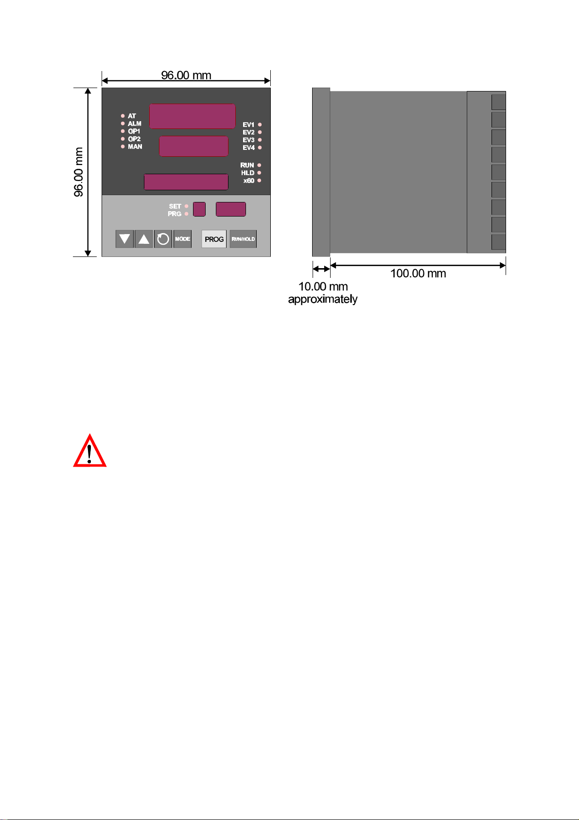
2.2 PANEL-MOUNTING
92.0 mm +0.8 -0.0
THE SETPOINT
PROGRAMMER
The panel on which the Setpoint
Programmer is to be mounted must
be rigid and may be up to 6.0mm
(0.25 inches) thick. The cut-out
required for a single etpoint
Programmer is as shown in Figure
2-1.
Several controllers may be installed
in a single cut-out, side-by-side. For
n Setpoint Programmers mounted
side-by-side, the width of the cut-out would be:
(96n - 4) millimetres or (7.56n - 0.16) inches.
The Setpoint Programmer is 100mm deep (measured from the rear face of the
front panel). The front panel is 96mm high and 96mm wide. When
panel-mounted, the front panel projects 10mm from the mounting panel. The
main dimensions of the Setpoint Programmer are shown in Figure 2-2.
Figure 2-1 Cut-out Dimensions
59216-2 2-1
Page 8
59216
Figure 2-2 Principal Dimensions
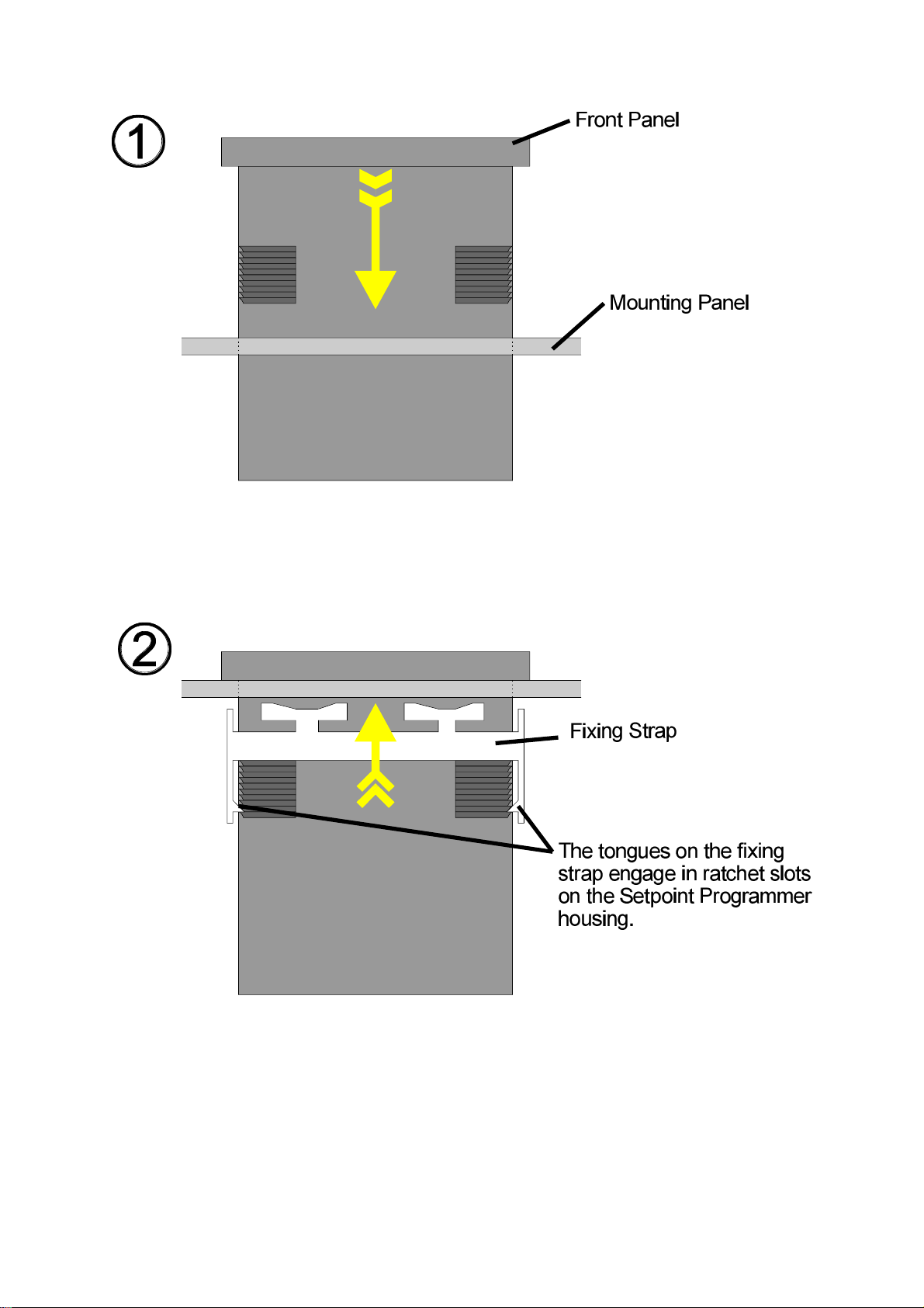
To panel-mount the Setpoint Programmer:
1. Insert the rear of the Setpoint Programmer housing through the cut-out
(from the front of the mounting panel) and hold the Setpoint Programmer
lightly in position against the panel. Ensure that the panel gasket is not
distorted and that the Setpoint Programmer is positioned squarely against
the mounting panel. Apply pressure to the front panel bezel only.
CAU TION: Do not remove the panel gasket, as this may result in
inadequate clamping of the instrument in the panel.
2. Slide the fixing strap in place (see Figure 2-3) and push it forward until it is
firmly in contact with the rear face of the mounting panel (the tongues on
the strap should have engaged in matching rachet positions on the
Setpoint Programmer housing and the fixing strap springs should be pushing
firmly against the mounting panel rear face).
Once the Set point Pro gram mer is in stalled in its mount ing panel, it may be
sub se quently re moved from its hous ing, if nec es sary, as de scribed in Sub sec tion
3.1.
2-2 59216-2
Page 9
59216
Figure 2-3 Panel-mounting the Setpoint Programmer
59216-2 2-3
Page 10
59216
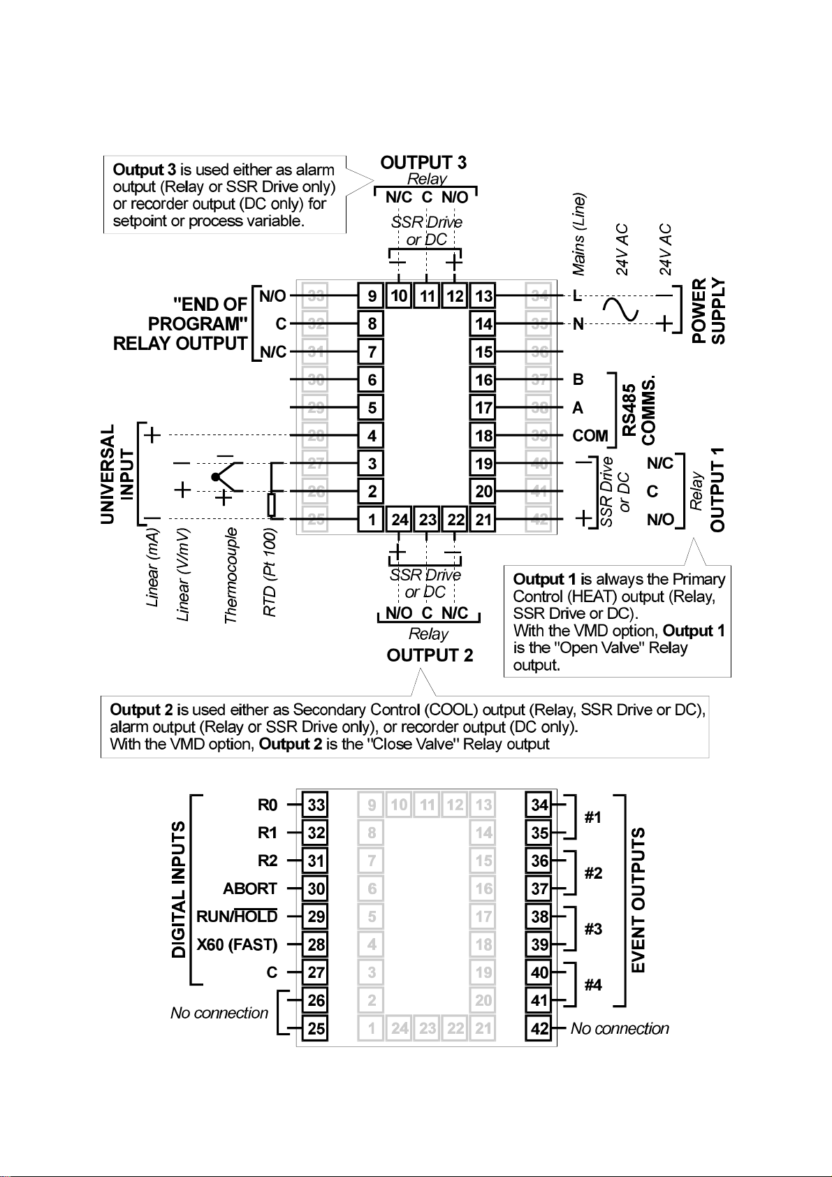
2.3 CONNECTIONS AND WIRING
Figure 2-4 Rear Terminals
2-4 59216-2
Page 11
59216
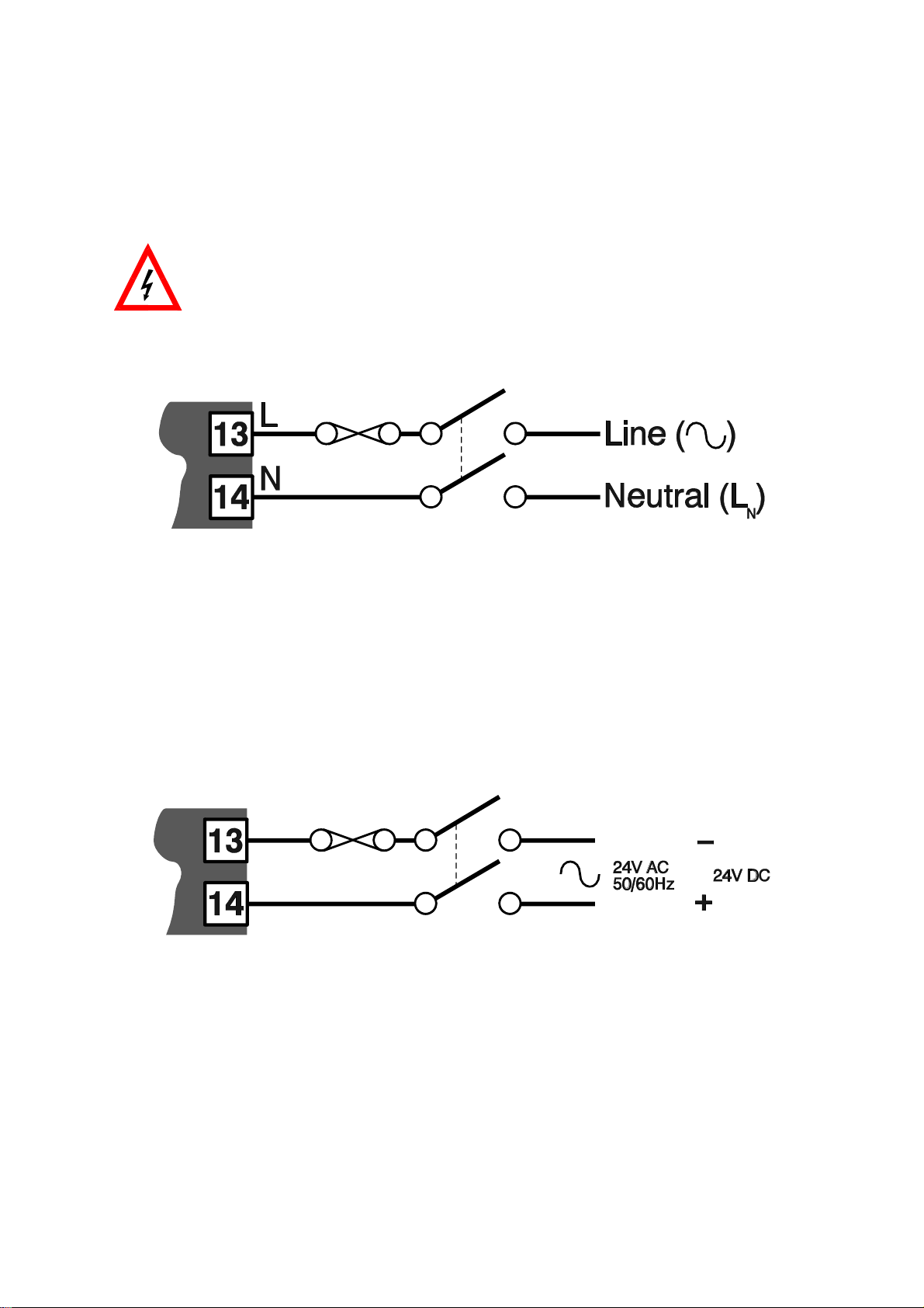
2.3.1 Mains (Line) In put
The Setpoint Programmer will operate on 96 - 264V AC 50/60Hz mains (line) supply.
The power consumption is approximately 4 VA.
CAUTION: This equipment is designed for installation in an enclosure
which provides adequate protection against electric shock. Local
regulations regarding electrical installation should be rigidly
observed. Consideration should be given to prevention of access to
the power terminations by unauthorised personnel. Power should be
connected via a two-pole isolating switch (preferably situated near
the equipment) and a 1A fuse, as shown in Figure 2-5.
Figure 2-5 Mains (Line) Sup ply Con nec tions
If the Setpoint Programmer has relay outputs in which the contacts are to
carry mains (line) voltage, it is recommended that the relay contact mains
(line) supply should be switched and fused in a similar manner but should
be separate from the Setpoint Programmer mains (line) supply.
2.3.2 24V (Nomi nal) AC/DC Sup ply
The supply connections for the 24V AC/DC option of the Setpoint Programmer are
as shown in Figure 2-6. Power should be connected via a two-pole isolating switch
and a 315mA slow-blow (anti-surge Type T) fuse.
Figure 2-6 24V AC/DC Sup ply Con nec tions
With the 24V AC/DC supply option fitted, these terminals will accept the following
supply voltage ranges:
24V (nominal) AC 50/60Hz - 20 - 50V
24V (nominal) DC - 22 - 65V
59216-2 2-5
Page 12
59216
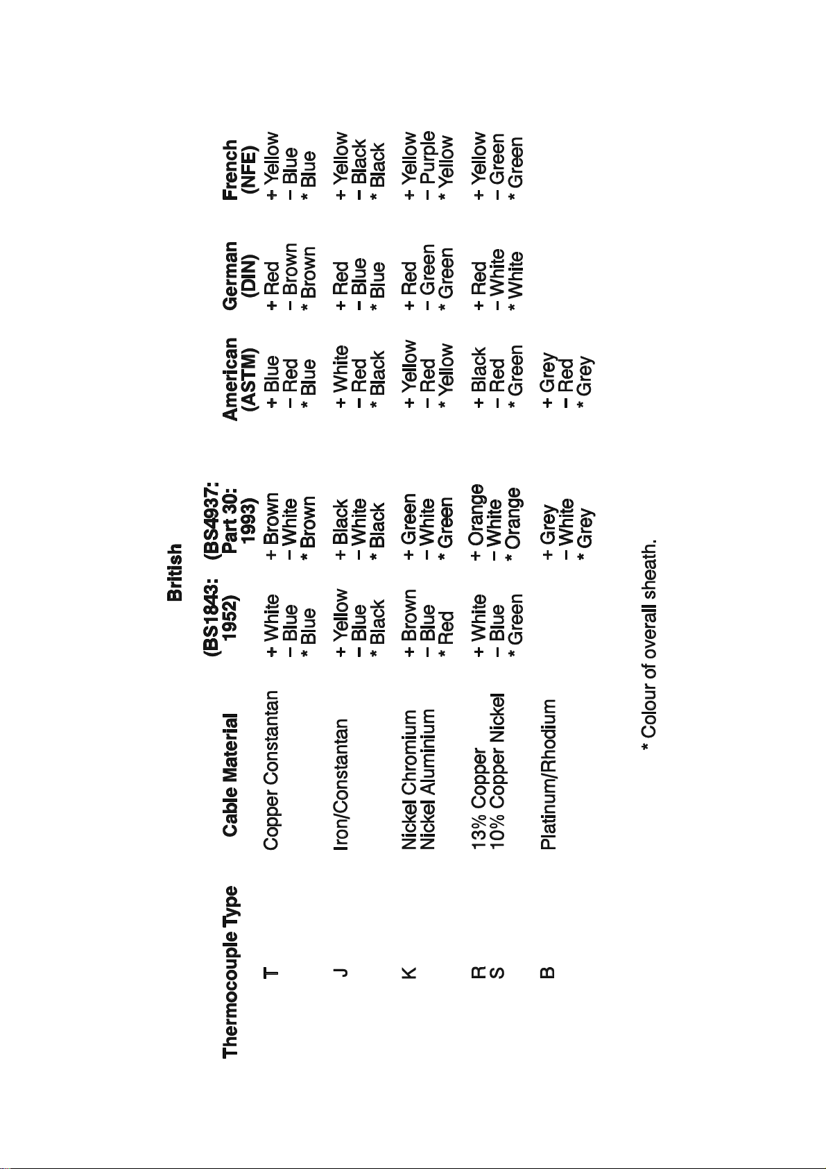
Table 2 -1 Ther mo cou ple Ca ble Col our Codes
2-6 59216-2
Page 13

59216
2.3.3 Ther mo cou ple In put
The correct type of thermocouple extension leadwire or compensating cable
must be used for the entire distance between the Setpoint Programmer and the
thermocouple, ensuring that the correct polarity is observed throughout. Joints in
the cable should be avoided, if possible. The Setpoint Programmer’s CJC facility
must be enabled (normal conditions) for this input (see Subsection 4.3).
NOTE: Do not run ther mo cou ple ca bles ad ja cent to power- carrying
con duc tors. If the wir ing is run in a con duit, use a sepa rate con duit
for the ther mo cou ple wir ing. If the ther mo cou ple is grounded, this
must be done at one point only. If the ther mo cou ple ex ten sion lead
is shielded, the shield must be grounded at one point only.
The colour codes used on thermocouple extension leads are shown in Table 2-1.
2.3.4 RTD In puts
The compensating lead should be connected to Terminal 3. For two-wire RTD
inputs, Terminals 2 and 3 should be linked. The extension leads should be of
copper and the resistance of the wires connecting the resistance element should
not exceed 5 ohms per lead (the leads should be of equal resistance).
2.3.5 Lin ear In puts
For linear mA input ranges, connection is made to Terminals 1 and 4 in the
polarity shown in Figure 2-4. For linear mV and V ranges, connection is made to
Terminals 2 and 3 in the polarity shown in Figure 2-4. For details of the linear input
ranges available, refer to Appendix A.
2.3.6 Digi tal In puts
These inputs will accept TTL, Open Collector or voltage-free (switch) connections.
A Digital Input Option PCB must be fitted and the External Option parameter (in
Configuration Mode - see Subsection 4.2 of this manual) must be set to inP or
both for these terminals to be operable. The degree of external selection/control is
defined by the External Selection parameter in Program Define Mode (see
Operator’s Manual, Section 8). It is assumed that all external selection/run control
functions are enabled for the purposes of this description.
Terminals 31 (R2) to 33 (R0) provide a binary-coded input which is used to select
the program:
59216-2 2-7
Page 14

59216
Digital Inputs = TTL Level Digital Inputs = Contavts (switches)
Digital Inputs Program Selected Digital Inputs Program Selected
R0 R1 R2 R0 R1 R2
0 0 0 Program 1 Closed Open Open Program 1
1 0 0 Program 2 Open Closed Open Program 2
0 1 0 Program 3 Closed Closed Open Program 3
1 1 0 Program 4 Open Open Closed Program 4
0 0 1 Program 5 Closed Open Closed Program 5
1 0 1 Program 6 Open Closed Closed Program 6
0 1 1 Program 7 Closed Closed Closed Program 7
1 1 1 Program 8 Open Open Open Program 8
For the Program Control inputs, the following convention has been adopted: for
TTL inputs OFF = logic 0, ON = logic 1; for contact (switch) inputs, OFF = open,
ON = closed.
Terminal 30 is the Program Abort control. It is edge-sensitive; an OFF-ON transition
at any time will cause an immediate Program Abort.
Terminal 29 provides the remote Run Program/Hold Program control and has an
identical effect to that of the Run/Hold key on the front panel. An OFF-ON
transition will cause the currently-selected program to be run (or to be resumed if
it is currently held); An ON-OFF transition will cause the currently-running program
to be held. Powering-up the Setpoint Programmer with this terminal ON will not
cause a program to run.
Terminal 28 provides the “x60" program timebase selection. This terminal is
level-sensitive: ON (contacts closed) = minutes/seconds, OFF (contacts open) =
hours/minutes). When the Setpoint Controller is powered-up, the initially-selected
timebase will be according to the level on this terminal at power-up.
NOTE: All re mote se lec tion/con trol func tions ex cept the Abort
func tion have prece dence over the cor re spond ing front panel
con trols. The “x60" func tion will also take prece dence over any
”Pre- set x60" pa rame ter set ting (see Op era tor Man ual, Sec tion 8).
2.3.7 Re lay Out puts
Out puts 1, 2 and 3: con tacts rated at 2A re sis tive at 120/240V AC.
End of Pro gram/Event out puts: con tacts rated at 5A re sis tive at 120/240V AC.
NOTE: With VMD con trol, ei ther Out put 1 or Out put 2 is switched on
(to open or close the valve) How ever, un der fault con di tions, both
Out put 1 and Out put 2 re lays could be switched on si mul ta ne ously.
For safety pur poses, an in ter lock can be in cluded which con nects
the sup ply to the mo tor via the “nor mally closed” con tacts on the
Out put 1 and Out put 2 re lays (see Fig ure 2-7).
2 -8 59216-2
Page 15

Figure 2-7 Valve Mo tor Drive Out puts with In ter lock
2.3.8 SSR Drive Out puts
59216
These outputs produce a time-proportioned non-isolated DC signal (0 - 4.3V
nominal, output impedance 250 ohms).
2.3.9 DC Out puts
See Appendix A.
2.3.10Event Out puts
These outputs are only available if the Event Output PCB is fitted and if the External
Option parameter in Configuration Mode (see Subsection 4.2 of this manual) is set
to either out or both. They are single pole single throw Normally Open relay
contacts. For the current segment of the currently-running/held program, these
outputs are in the states defined by the Event parameter (see Operator’s Manual,
Section 8) for that segment. 0 = open, 1 = closed.
2.3.11RS485 Se rial Com mu ni ca tions Link
The “A” terminal (Terminal 17) on the Setpoint Programmer should be connected
to the “A” terminal on the master device; the “B” terminal (Terminal 16) on the
Setpoint Programmer should be connected to the “B” terminal on the master
device. Where several Setpoint Programmers are connected to one master port,
the master port transceiver in the active state should be capable of driving a load
of 12kΩ per Setpoint Programmer; the master port transceiver in the passive state
must have pull-up/pull-down resistors of sufficiently low impedance to ensure that
it remains in the quiescent state whilst supplying up to +/-100
Programmer transceivers in the high impedance state.
µA each to the Setpoint
59216-2 2-9
Page 16
59216
SEC TION 3
INTERNAL LINKS AND SWITCHES
3.1 REMOVING THE SETPOINT PROGRAMMER FROM ITS HOUSING
CAUTION: Before removing the Setpoint Programmer from its housing,
ensure that all power has been removed from the rear terminals.
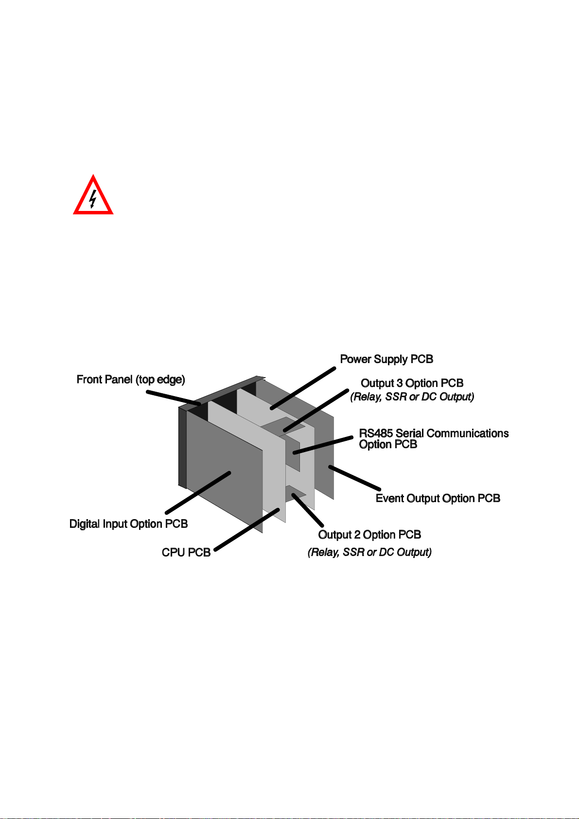
To withdraw the Setpoint Programmer from its housing, simply grip the side edges
of the front panel (there is a finger grip on each edge) and pull the panel
forwards. This will release the Setpoint Programmer from its rear connectors in the
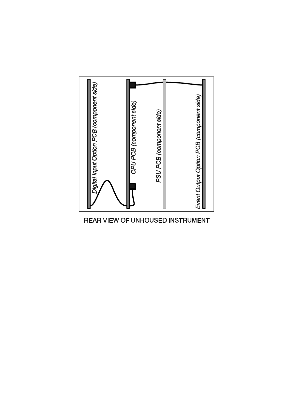
housing and will give access to the PCBs. Take note of the orientation of the
Setpoint Programmer for subsequent replacement into the housing.The positions of
the PCBs are shown in Figure 3 -1 .
Figure 3-1 PCB Positions
3 -1 59216-3
Page 17
59216
Figure 3-2 Removing the Output 2/Output 3 Option PCBs
59216-3 3-2
Page 18
59216
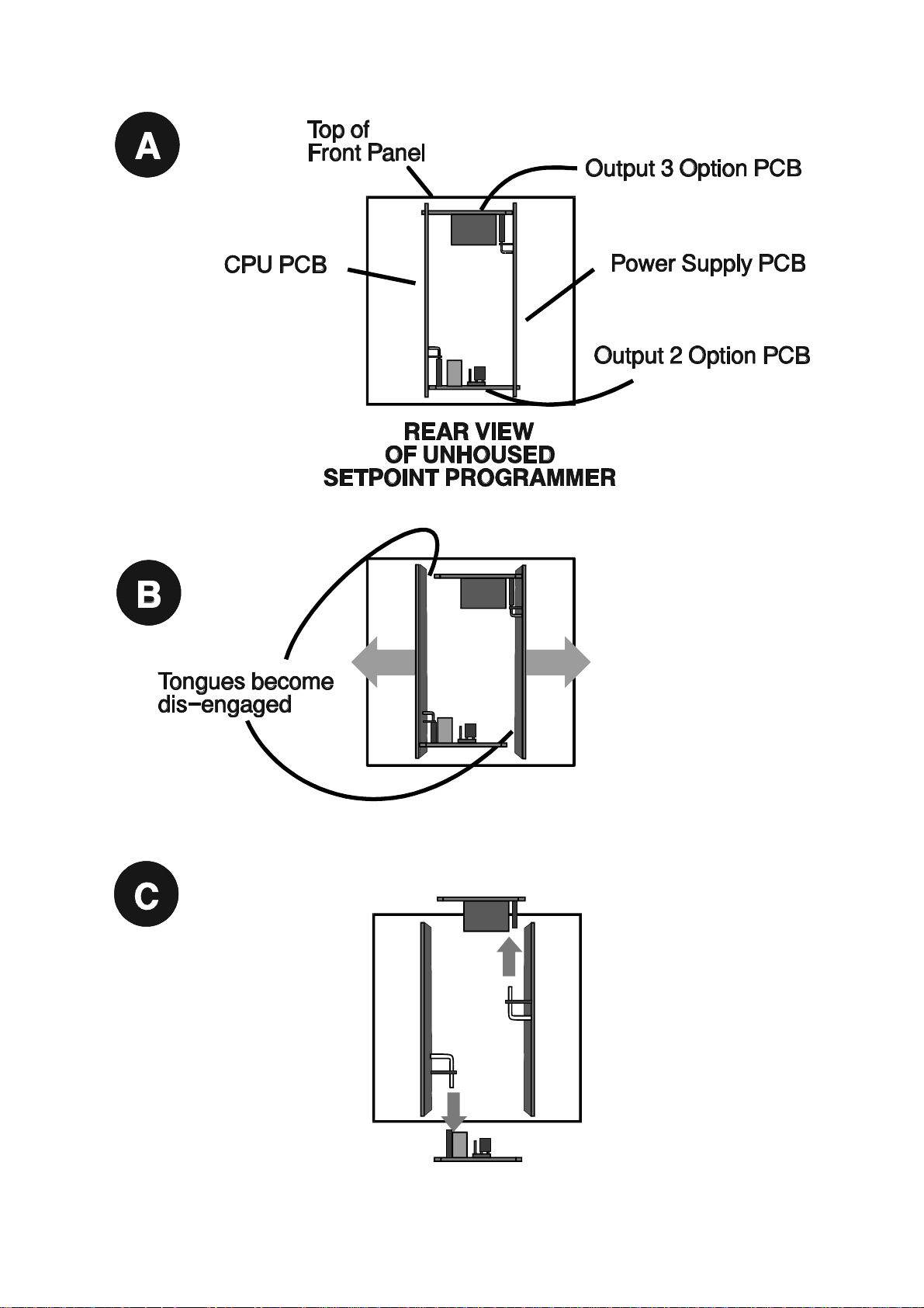
3.2 REMOVING/REPLACING THE OUTPUT 2/OUTPUT 3 OPTION PCBs
With the Setpoint Programmer removed from its housing:
1. Gently push the rear ends of the CPU PCB and Power Supply PCB apart
slightly, until the two tongues on each of the Output 2/Output 3 Option PCBs
become dis-engaged - see Figure 3-2B; The Output 2 Option PCB tongues
engage in holes in the Power Supply PCB and the Output 3 Option PCB
tongues engage in holes on the CPU PCB.
2. Carefully pull the required Option PCB (Output 2 or Output 3) from its
connector (Output 2 Option PCB is connected to the CPU PCB and Output 3
Option PCB is connected to the Power Supply PCB) - see Figure 3-2C. Note
the orientation of the PCB in preparation for its replacement.
Adjustments may now be made to the link jumpers on the CPU PCB, the Output
2/Output 3 Option PCBs (if DC output) and (if fitted) the DC Output 1 PCB. The
replacement procedure is a simple reversal of the removal procedure.
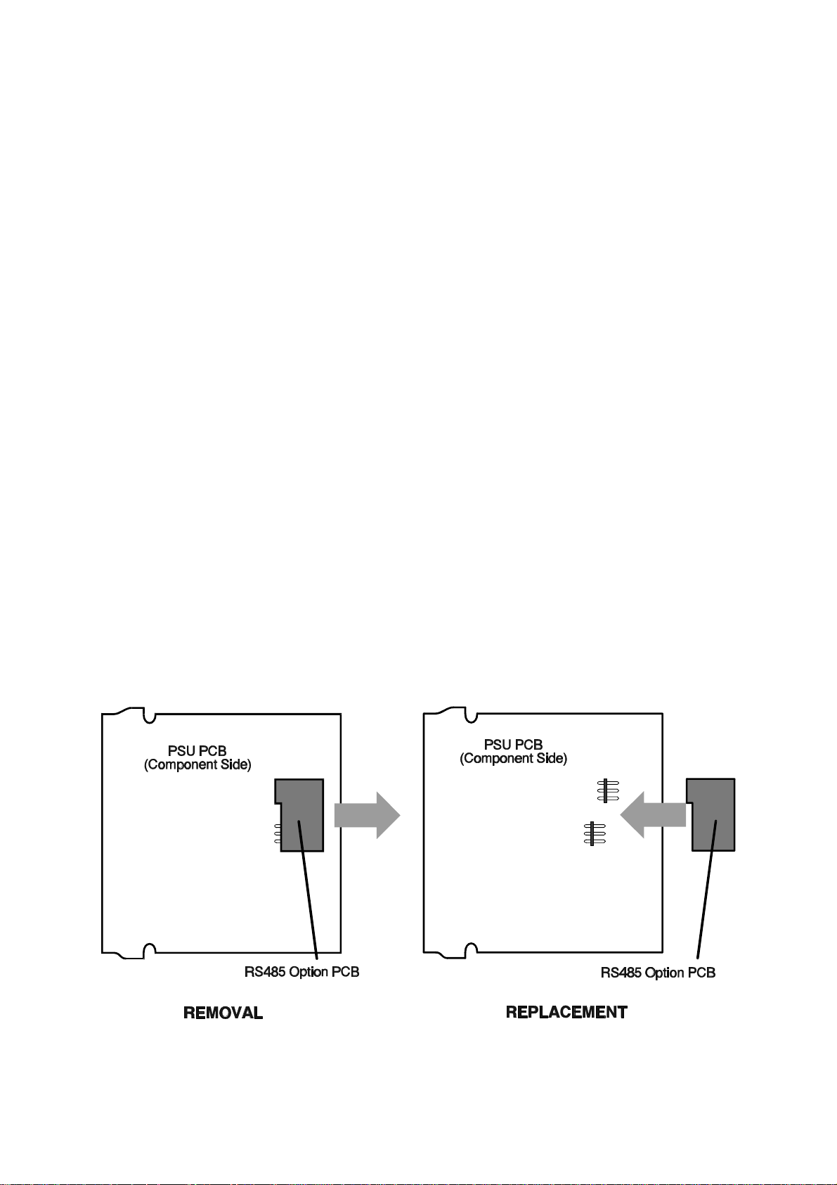
3.3 REMOVING/REPLACING THE RS485 COMMUNICATIONS OPTION PCB
The RS485 Communications Option PCB is mounted on the inner surface of the
Power Supply PCB and can be removed when the Setpoint Programmer is
removed from its housing (see Subsection 3.1) Figure 3 -3 illustrates the
removal/replacement procedure. It is not necessary to remove the Output
2/Output 3 Option PCBs to perform this procedure.
Figure 3-3 Re mov ing/Replacing the RS485 Communications Op tion PCB
3-3 59216-3
Page 19
59216
3.4 INSTALLING/REMOVING THE DIGITAL INPUT OPTION PCB
The location of the Digital Input Option PCB is shown in Figure 3-4. It is connected
to the CPU PCB via a flexi-strip connector, as shown.
Figure 3-4 Location of Digital Input Option PCB and
Event Output Option PCB
To install the Digital Input Option PCB:
1. Hold the PCB ap proxi mately in po si tion and care fully in sert the free end
of the flexi- strip ca ble into the socket near the bot tom edge of the CPU PCB
(en sur ing that none of the pins on the end of the flexi- strip be come bent
and that the flexi- strip is not twisted).
2. Fully in sert the Digi tal In put Op tion PCB into its con nec tor at the rear of
the front panel (when the PCB is fully in serted, it will be come en gaged in
the slots above and be low its con nec tor).
To remove the Digital Input Option PCB:
1. Dis- engage the PCB from its slots (above and be low the con nec tor at the
rear of the front panel) and with draw the PCB clear of the con nec tor.
2. Dis con nect the flexi- strip from the con nec tor near the bot tom edge of
the CPU PCB.
3. Re move the Digi tal In put Op tion PCB com pletely from the in stru ment.
59216-3 3-4
Page 20

59216
3.5 INSTALLING/REMOVING THE EVENT OUTPUT OPTION PCB
The location of the Event Output Option PCB is shown in Figure 3 -4 . It is connected
to the CPU PCB via a flexi-strip connector, as shown.
To install the Event Output Option PCB:
1. Hold the PCB ap proxi mately in po si tion and care fully in sert the free end
of the flexi- strip ca ble into the socket near the top edge of the CPU PCB
(en sur ing that none of the pins on the end of the flexi- strip be come bent
and that the flexi- strip is not twisted).
2. Fully in sert the Event Out put Op tion PCB into its con nec tor at the rear of
the front panel (when the PCB is fully in serted, it will be come en gaged in
the slots above and be low its con nec tor).
To remove the Event Output Option PCB:
1. Dis- engage the PCB from its slots (above and be low the con nec tor at the
rear of the front panel) and with draw the PCB clear of the con nec tor.
2. Dis con nect the flexi- strip from the con nec tor near the top edge of the
CPU PCB.
3. Re move the Event Out put Op tion PCB com pletely from the in stru ment.
3.6 REPLACING THE SETPOINT PROGRAMMER IN ITS HOUSING
To replace the Setpoint Programmer, simply align the CPU PCB and Power Supply
PCB with their guides and connectors in the housing and slowly but firmly push the
Setpoint Programmer into position.
CAU TION: En sure that the in stru ment is cor rectly ori en tated. A stop will
op er ate if an at tempt is made to in sert the in stru ment in the wrong
ori en ta tion (e.g. upside- down). This stop must not be over- ridden.
3-5 59216-3
Page 21
59216
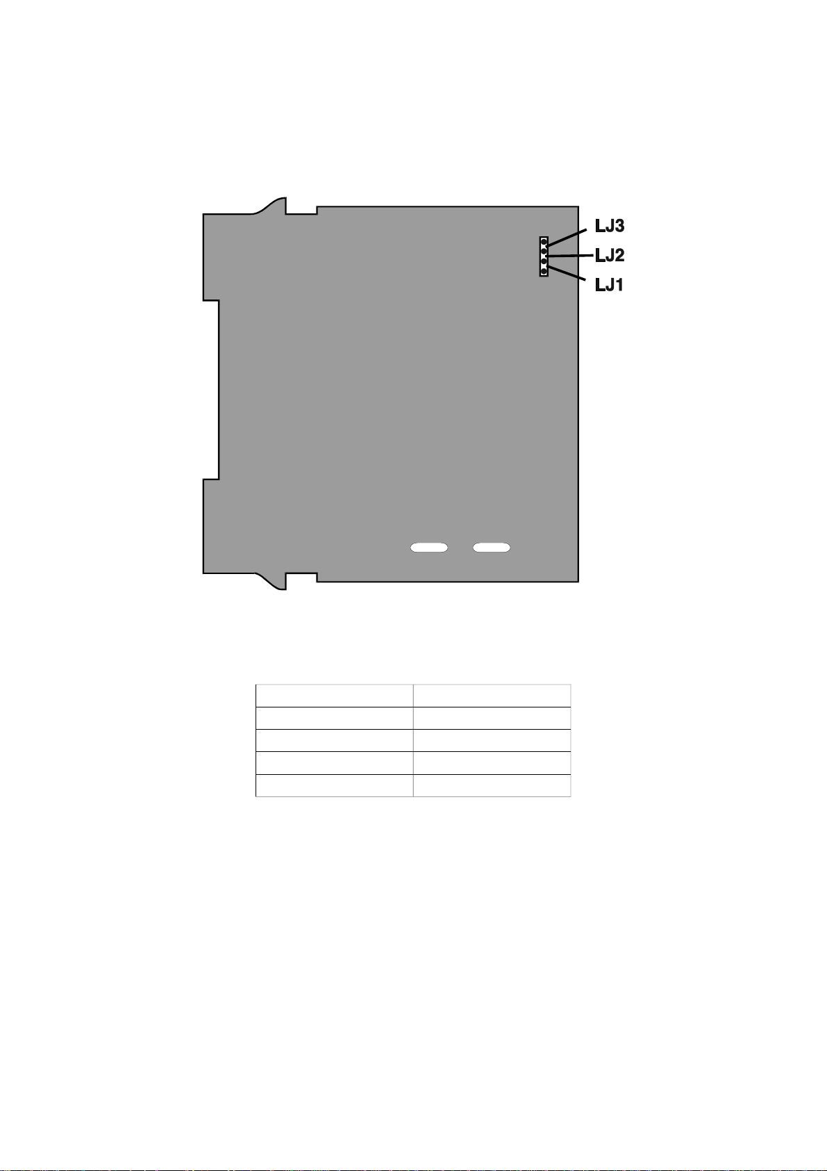
3.7 SELECTION OF INPUT TYPE
The se lec tion of in put type is ac com plished on link jump ers LJ1/LJ2/LJ3 on the CPU
PCB (see Fig ure 3-5 and Ta ble 3 -1 ).
Figure 3-5 CPU PCB (Relay/SSR Drive Output 1)
Table 3 -1 Input Type Selection
Input Type Link Jumper Fitted
RTD or DC (mV) None (parked)
Thermocouple LJ3
DC (mA) LJ2
DC (v) LJ1
59216-3 3-6
Page 22
59216
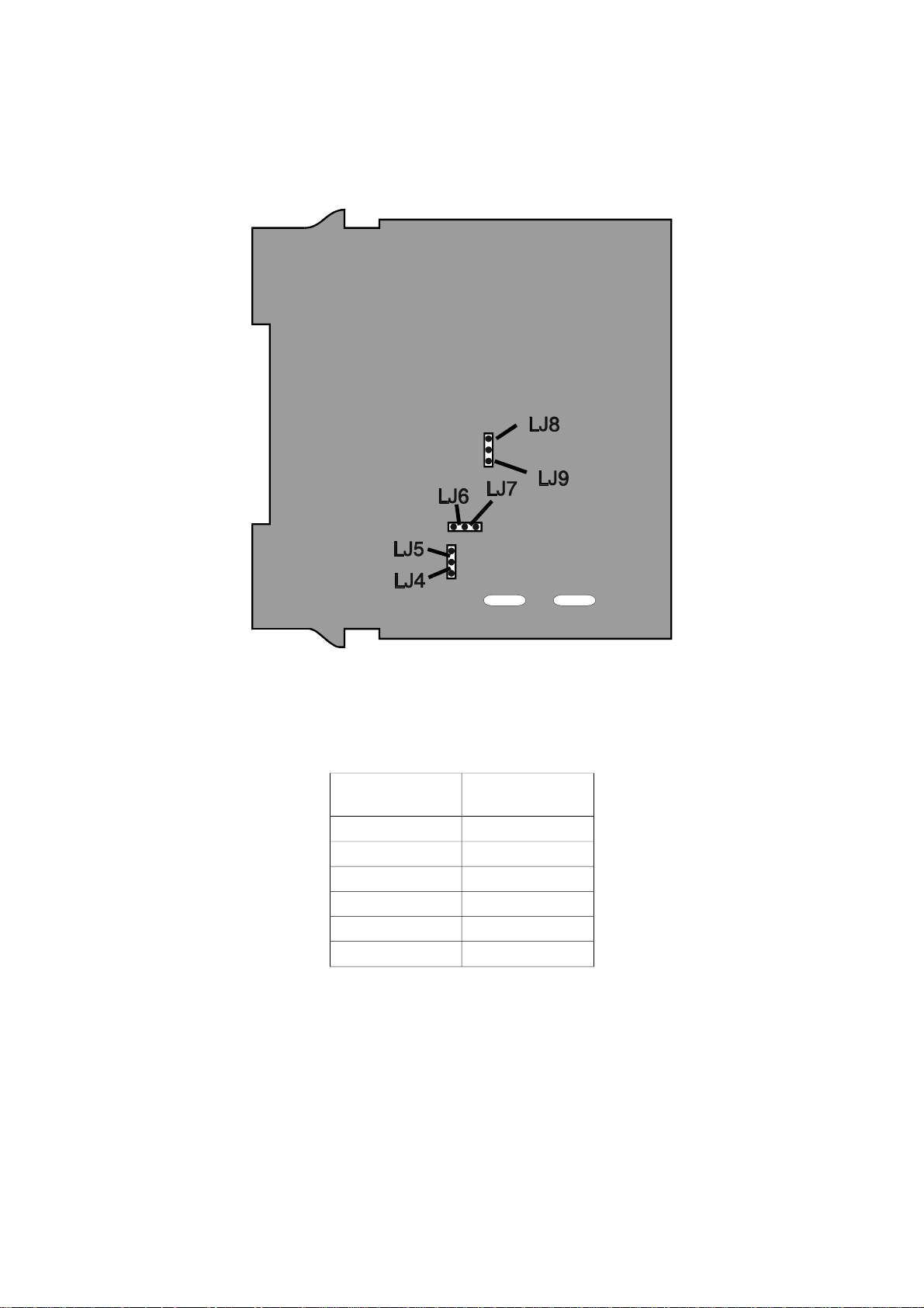
3.8 SELECTION OF PRIMARY OUTPUT (OUTPUT 1) TYPE
The re quired type of Out put 1 is se lected by Link Jump ers LJ4/LJ5/LJ6/LJ7/LJ8/LJ9
on the PSU PCB (see Fig ure 3-6 and Ta ble 3 -2 ).
Figure 3-6 PSU PCB Link Jumpers
Table 3 -2 Output 1 Type Selection
Output Type Link Jumpers
Fitted
Relay LJ5 & LJ6
SSR Drive LJ4 & LJ7
DC (0 - 10V) LJ8
DC (0 - 20mA) LJ9
DC (0 - 5V) LJ8
DC (4 - 20mA) LLJ9
3 -7 59216-3
Page 23

59216
3.9 OUTPUT 2 TYPE/OUTPUT 3 TYPE
The type of output for Output 2 and Output 3 is determined by the Option PCB
fitted in the appropriate position (see Figure 3 -1 ) and, in the case of the DC
Output Option PCB being fitted, the setting of Link Jumpers LJ8 and LJ9 on that
Option PCB (see Figure 3-7 and Table 3 -3 ). There are three types of option PCB
which may be used for Output 2 and Output 3:
1. Re lay Out put Op tion PCB (no link jump ers)
2. SSR Out put Op tion PCB (no link jump ers)
3. DC Out put Op tion PCB (link jump ers as shown in Fig ure 3 -7 )
Figure 3-7 DC Out put Option PCB (Output 2/Output 3)
Table 3 -3 Output 2/Output 3 DC Output Type Selection
Output Type Link Jumpers Fitted
DC (0 - 10V) LJ8
DC (0 - 20mA) LJ9
DC (0 -5V) LJ8
DC (4 - 20mA) LJ9
59216-3 3-8
Page 24

59216
SECTION 4
CONFIGURATION MODE
4.1 ENTRY INTO CONFIGURATION MODE
The Setpoint Programmer is then in Configuration Mode:
NOTE: Changes to Con figu ra tion pa rame ters (e.g. in put range, out put
use and type) will cause the Pro gram De fine Mode and Con trol ler
De fine Mode pa rame ters to be set to their de fault val ues. Ad just all
Con figu ra tion Mode pa rame ters to their de sired val ues be fore
ad just ing Pro gram De fine and Con trol ler De fine Mode pa rame ters.
4.2 HARDWARE DEFINITION CODE
This specifies the hardware fitted (input type, output types etc.); this must be
compatible with the hardware actually fitted. It can be accessed by pressing the
Down and Scroll keys together. The Message Display will then show:
and lower main display will be of the form:
4-1 59216-4
Page 25

59216
The displayed code may be incremented/decremented using the Up/Down keys
as required. The maximum setting available for this code is 4777. For example,
the code for a thermocouple input, DC 4 - 20mA primary output (Output 1) and
relay Output 3 would be 2701. When the code is first altered, the code display will
flash, until the desired value is displayed and confirmed by pressing the MODE
key.
NOTE: It is essential that this code is changed promptly whenever there is a
change to the Setpoint Programmer’s hardware configuration (change of
input/output type, alarm/recorder output added/removed etc.). The
Setpoint Programmer software depends upon this code to operate
correctly.
Hardware Definitions may be viewed as Read Only displays in Base Mode by
pressing the Scroll and Down keys simultaneously.
Whilst the Hardware Definition Code is displayed, pressing the Scroll key will cause
the Message Display to change to:
and the lower main dis play to change to one of:
The desired setting can be achieved using the Up/Down keys.
59216-4 4-2
Page 26

59216
Press the Scroll key to change the Message Display to:
and the lower main display to one of:
The desired setting can be achieved using the Up/Down keys. If the External
Option parameter has not been set to inP or both , pressing the Scroll key will
return to the initial External Option parameter display. If the External Option
parameter has been set to either inP or both, pressing the Scroll key will change
the Message Display to:
and the lower main display to one of:
Digital Inputs = TTL Level Digital Inputs = Contavts (switches)
Digital Inputs Program Selected Digital Inputs Program Selected
R0 R1 R2 R0 R1 R2
0 0 0 Program 1 Closed Open Open Program 1
1 0 0 Program 2 Open Closed Open Program 2
0 1 0 Program 3 Closed Closed Open Program 3
1 1 0 Program 4 Open Open Closed Program 4
0 0 1 Program 5 Closed Open Closed Program 5
1 0 1 Program 6 Open Closed Closed Program 6
0 1 1 Program 7 Closed Closed Closed Program 7
1 1 1 Program 8 Open Open Open Program 8
For the Program Control inputs, the following convention has been adopted: for
TTL inputs OFF = logic 0, ON = logic 1; for contact (switch) inputs, OFF = open,
ON = closed.
The desired setting can be achieved using the Up/Down keys. Pressing the Scroll
key will then return to the initial External Option parameter display. To exit from the
Hardware Definition Code facility, press the Down and Scroll keys simultaneously
(which will cause a return to the normal Configuration Mode). Alternatively, either
of the methods of exit from Configuration Mode (see Subsection 4.5 ) may be used
here.
4-3 59216-4
Page 27

59216
4.3 CONFIGURATION MODE PARAMETERS
The Configuration Mode parameters are presented for view/edit in the following
sequence:
Parameter Message
Function Available Settings/Values
Display
Primary Input Range
1
Displayed code defines
input type & range (see
Appendix A)
Control Action Specifies control action
of Output 1
2
Alarm 1 Type Specifies Alarm 1
operation
Alarm 2 Type Specifies Alarm 2
operation
(Lower Main Display)
See Appendix A .
Standard, direct-acting
Standard, reverse-acting*
VMD, direct-acting I
VMD, reverse-acting I
Process High*
Process Low
Deviation
Band
None
Process High*
Process Low
Alarm Inhibit (see
Subsection 4.4)
* Default value/setting
I Not available if Output 1 and Output 2 are not relay outputs (see Subsection 4.2).
Specifies which alarms
are inhibited
Deviation
Band
None
No inhibit*
Alarm 1
Alarm 2
Both alarms
59216-4 4-4
Page 28

59216
Parameter Message
Function Available Settings/Values
Display
Output 2 Usage
NOTE: This
Specifies use of
Output 2
3
parameter is not
available if Control
Action is set to Mdd
or Mdr - Output 2 is
automatically used
as a control output.
Output 3 Usage Specifies use of
Output 3
4
(Lower Main Display)
Control Output
2
Alarm 2 (direct)
Alarm 2 (reverse)
Alarm 1 OR 2 (direct)
Alarm 1 OR 2 (reverse)
Alarm 1 AND 2 (direct)
Alarm 1 AND 2 (reverse)
Loop Alarm (direct)
Loop Alarm (reverse)
Alarm 1 (direct)
Alarm 1 (reverse)
Segment Mode Defines parameter used
to specify duration of
each segment (along
with Final SP value)
End of Program Relay operation
Selects when End of
Program relay is
energised
Alarm 1 OR 2 (direct)
Alarm 1 OR 2 (reverse)
Alarm 1 AND 2 (direct)
Alarm 1 AND 2 (reverse)
Loop Alarm (direct)
Loop Alarm (reverse)
Recorder Output (SP)
Recorder Output (PV)
Time*
Ramp Rate H
When program ends*
While program runs
Event State Selects whether Event
Held
Output states are held
or reset at End of
Reset*
Program
* Default value/setting
H When x60 = OFF, Time = hours/minutes and Ramp Rate = LSD/hour
When x60 = ON, Time = Minutes/seconds and Ramp Rate = LSD/minute
4-5 59216-4
Page 29

59216
Parameter Message
Baud Rate
Communications Protocol
Communications Address
CJC Enable/Disable
5
5
56,
7
Number of Lock Codes
Lock Code
8
Display
If 1 Lock
Code, or:
Function Available Settings/Values
Selects Baud rate for
RS485 Communications
Selects protocol for
RS485 Communications
Selects RS485
Communications
address
Enables/disables Cold
Junction Compensation
Selects one or two lock
codes to be used
Dislays current lock
code value(s)
(Lower Main Display)
Numeric value: 1200, 2400,
4800* or 9600
ASCII*
MODBUS RTU, no parity
MODBUS RTU, odd parity
MODBUS RTU, even parity
ASCII protocol: 1* - 99
MODBUS RTU protocol: 1 - 255
Enabled*
Disabled
1* (common code) or 2
(separate codes for Controller
Define Mode and Program
Define Mode)
Read Only - No adjustment in
Configuration Mode - see
Operator's manual.
followed
by:
if 2 Lock
Codes
* Default value/setting
59216-4 4-6
Page 30

59216
NOTES ON CONFIGURATION PARAMETERS
1. The primary input range deafult setting is dependent uon the hardware fitted, as
indicated in the Hardware definition Code (see Subsection 4.2):
Input Hardware Fitted Default Setting
Thermocouple
RTD/Linear (mV)
Linear (mA) 3414 (4 - 20mA)
Linear (V) 4446 (0 - 10V)
2. If Output 2 is selected to be the secondary (COOL) control output, its action is always
the complement of the action of Output 1.
3. The default setting for Output 2 Usage is Alarm 2 hardware output, direct-acting (if a
relay/SSR drive output) or secondary (COOL) control output (if DC output).
4. The default setting for Output 3 Usage is Alarm 1 hardware output, direct-acting (if a
relay/SSR drive output) or Process Variable Recorder Output (if a DC output).
5. Not available if the Hardware Definition Comms parameter is set to nonE .
6. Not available if the Hardware Definition Comms parameter is set to MAS (see
Subsection 4.2).
1419 (Type "J", 0 - 760°C)
7220 (RTD Pt100 0 - 800°C)
7. Not available if input type is not thermocouple (see Subsection 4.2 ). If the CJC is
disabled, the initial display in Operator Mode will show horizontal bars flashing in the lower
main display.
8. Message Display will show Lock Code for 1 lock code or Lock P (Program Define Mode)
followed by Lock C (Controller Define Mode) for 2 lock codes.
4.4 ALARM INHIBIT FACILITY
On power-up, an “alarm” condition may occur, based on the alarm value, the
process variable value and, if appropriate to the alarm type, the setpoint value.
This would normally activate an alarm; however, if the pertinent alarm is inhibited,
the alarm indication is suppressed and the alarm will remain inactive. This will
prevail until the “alarm” conditon returns to the “inactive” state, whereafter the
alarm will operate normally.
4.5 EXIT FROM CONFIGURATION MODE
To leave Configuration Mode, depress the Up and Scroll keys simultaneously.
NOTE: An auto matic exit to Base Mode will be made if, in
Con figu ra tion Mode, there is no front panel key ac tiv ity for five
min utes.
The exit is made via the power-up self-test routines which include a lamp test.
4 -7 59216-4
Page 31

59216
SECTION 5
SERIAL COMMUNICATIONS - ASCII PROTOCOL
The Setpoint Programmer may be equipped with a three-wire RS485-compatible
serial communications facility, by which means communication may occur
between the Setpoint Programmer and a master device (e.g. a computer or
terminal) or up to 99 slave devices.
5.1 RS485 CONNECTIONS
The connections for the serial communications option are shown in Figure 2 -4 and
described in Subsection 2.3.11 . Communication is at a user-selectable rate from
the range 1200, 2400, 4800 and 9600 Baud and the cable used should be
suitable for data transfer at the selected rate over the required distance.
Transmitters/receivers conform to the recommendations in the EIA Standard RS485.
5.2 COMMUNICATIONS ENABLE/DISABLE
When Communications are enabled (in Controller Define Mode - see Operators’
Manual), the Setpoint Programmer parameters may be adjusted by the master
device via the serial communications link. If communications are disabled, the
Setpoint Programmer will not adjust or change any parameters in response to
commands received from the master device and will send a negative
acknowledgement in response to such commands. Whether communications are
enabled or disabled, the Setpoint Programmer will return the requested
information in response to a Type 2 Interrogation message (see Subsection 5.4.2 )
from the master device.
5.3 SELECTION OF COMMUNICATIONS ADDRESS
The address for each Setpoint Programmer is defined in Configuration Mode (see
Subsection 4.3). Up to 32 Setpoint Programmers, each with a unique address, may
be connected to the master device.
5.4 ASCII COMMUNICATIONS PROTOCOL
The ASCII protocol assumes half duplex communications. All communication is
initiated by the master device. The master sends a command or query to the
addressed slave and the slave replies with an acknowledgement of the
command or the reply to the query. All messages, in either direction, comprise:
(a) A Start of Mes sage char ac ter
- R (Pro gram mer Pa rame ters) or L (Con trol ler Pa rame ters)
(b) One or two ad dress char ac ters (uniquely de fin ing the slave)
(c) A pa rame ter/data char ac ter string {DATA}
59216-5 5-1
Page 32

59216
(d) An End of Mes sage char ac ter
Messages from the master device may be one of five types:
Type 1: {S} {N} ? ? *
Type 2: {S} {N} {P} {C} * or R {N} {P} {C} *
Type 3: {S} {N} {P} # {DATA} * or R {N} {P} # {DATA *
Type 4: {S} {N} {P} I * or R {N} {P} I *
Type 5: {S} {N} \ P S S ? *
where all characters are in ASCII code and:
{S} is the Start of Mes sage char ac ter L (Hex 4C) or R (Hex 52). L is used for
Con trol ler pa rame ters; R is used for Pro gram mer pa rame ters.
{N} is the slave Set point Pro gram mer ad dress (in the range 1 - 99);
ad dresses 1 - 9 may be rep re sented by a sin gle digit (e.g. 7) or in
two- digit form, the first digit be ing zero (e.g. 07).
{P} is a char ac ter which iden ti fies the pa rame ter to be
in ter ro gated/modi fied - see Ta ble 5 -2 (Programmer parameters) and
Ta ble 5 -4 (Controller parameters).
{C}is the com mand (see Subsection 5.4.2)
# in di cates that {DATA} is to fol low (Hex 23)
{DATA} is a string of nu meri cal data in AS CII code (see Ta ble 5 -1 )
P is the Pro gram Num ber
S S is the Seg ment Num ber (01 to 16)
* is the End of Mes sage char ac ter (Hex 2A)
No space char ac ters are per mit ted in mes sages. Any syn tax er rors in a re ceived
mes sage will cause the slave con trol ler to is sue no re ply and await the Start of
Mes sage char ac ter.
Table 5 -1 {DATA} Element - Sign/Decimal Point Position
{DATA} Content Data Format {DATA} Content Data Format
abcd0 +abcd abcd5
abcd1 +abc.d abcd6
abcd2 +ab.cd abcd7
abcd3 +a.bcd abcd8
5-2 59216-5
−abcd
−abc.d
−ab.cd
−a.bcd
Page 33

59216
5.4.1 Type 1 Mes sage
L {N} ? ? *
This message is used by the master device to determine whether the addressed
slave Setpoint Programmer is active. The reply from an active slave is
L {N} ? A *
An inactive Setpoint Programmer will give no reply.
5.4.2 Type 2 Mes sage
L {N} {P} {C} * or R {N} {P} {C} *
This type of message is used by the master device to interrogate or modify a
parameter in the addressed Setpoint Programmer. {P} identifies the parameter as defined in Table 5-2 (Programmer Parameters) or Table 5 -4 (Controller
Parameters) - and {C} represents the command to be executed, which may be
one of the following:
+ (Hex 2B) - In cre ment the value of the pa rame ter de fined by {P}
– (Hex 2D) - Dec re ment the value of the pa rame ter de fined by {P}
? (Hex 3F) - De ter mine the cur rent value of the pa rame ter de fined by {P}
The reply from the addressed Setpoint Programmer is of the form:
L {N} {P} {DATA} A * or R {N} {P} {DATA} A *
where {DATA} comprises five ASCII-coded digits whose format is shown in Table
5-1. The data is the value requested in a query message or the new value of the
parameter after modification. If the action requested by the message from the
master device would result in an invalid value for that parameter (either because
the requested new value would be outside the permitted range for that
parameter or because the parameter is not modifiable), the Setpoint Programmer
replies with a negative acknowledgement:
L {N} {P} {DATA} N * or R {N} {P} {DATA} N *
The {DATA} string in the negative acknowledgement reply will be indeterminate. If
the process variable or the deviation is interrogated whilst the process variable is
outside the range of the Setpoint Programmer, the reply is:
L {N} {P} < ? ? > 0 A *
if the process variable is over-range, or
L {N} {P} < ? ? > 5 A *
if the process variable is under-range.
59216-5 5-3
Page 34

59216
Scan Tables
A parameter identifier character “]” in the message from the master device
indicates that a “Scan Table” operation is required. This provides a facility for
interrogating the values of a group of parameters and status in a single message
from the master device. The reply to such a command would be in the form:
L {N} ] xx aaaaa bbbbb ccccc ddddd eeeee A *
for Controller Scan Table, or
R {N} ] 25 P ss VVVVV TTTT CCCC SSSSS EEEE A *
for a Program Scan Table. For the Controller Scan Table response, xx is the
number of data digits to follow; this is 20 for a single-control-output instrument and
25 for a dual-control-output instrument. For further information, refer to Subsections
5.11 and 5.16.
5.4.3 Type 3 Mes sage
L {N} {P} # {DATA} * or R {N} {P} # {DATA} *
This message type is used by the master device to set a parameter to the value
specified in {DATA}. The command is not implemented immediately by the slave
Setpoint Programmer; the slave will receive this command and will then wait for a
Type 4 message (see below). Upon receipt of a Type 3 message, if the {DATA}
content and the specified parameter are valid, the slave Setpoint Programmer
reply is of the form:
L {N} {P} {DATA} I * or R {N} {P} {DATA} I *
(where I = Hex 49) indicating that the Setpoint Programmer is ready to implement
the command. If the parameter specified is invalid or is not modifiable or if the
desired value is outside the permitted range for that parameter, the Setpoint
Programmer replies with a negative acknowledgement in the form:
L {N} {P} {DATA} N * or R {N} {P} {DATA} N *
5.4.4 Type 4 Mes sage
L {N} {P} I * or R {N} {P} I *
This type of message is sent by the master device to the addressed slave Setpoint
Programmer following a successful Type 3 transaction with the same slave
Setpoint Programmer. Provided that the {DATA} content and the parameter
specified in the preceding Type 3 message are still valid, the slave Setpoint
Programmer will then set the parameter to the desired value and will reply in the
form:
5 -4 59216-5
Page 35

59216
L {N} {P} {DATA} A *
or
R {N} {P} {DATA} A *
where {DATA} is the new value of the parameter. If the new value or parameter
specified is invalid, the slave Setpoint Programmer will reply with a negative
acknowledgement in the form:
L {N} {P} {DATA} N *
or
R {N} {P} {DATA} N *
where {DATA} is in de ter mi nate. If the immediately- preceding mes sage re ceived
by the slave Set point Pro gram mer was not a Type 3 mes sage, the Type 4 mes sage
is ig nored.
5.5 PROGRAMMER PARAMETERS
(Start of Message character = R)
The Programmer Parameters and their identifier characters are listed in Table 5 -2
and their functions are shown in Table 5-3.
Unless otherwise stated, the {DATA} element will follow the standard five-digit
format and the decimal point position must be correct for the new value to be
accepted and for modification to occur.
Table 5 -2 Programmer Parameters and Identifiers
Identifier Parameter/Command Comments Type
A Segment Number Selects segment in selected
program
B Final Setpoint Value In selected segment Read/Write
C Segment Time/Ramp Rate In selected segment Read/Write
G Number of Cycles Programmed For selected program Read/Write
H Number of Cycles Completed For selected program Read Only
I Current Segment Number In currently-running/held program Read Only
J Segment Time Remaining In currently-running segment Read Only
K Programmer Commands Program control/selection Write Only
L Programmer Status 1 Summary of Programmer Parameters Read Only
M Current Setpoint Value In currently-running/held program Read Only
N Current Segment Event Status Status of each of four Events Read Only
P Current Program Number Indicates program currently
running/held
Q Delay Defines delay to start of all
programm
Read/Write
Read Only
Read/Write
59216-5 5-5
Page 36

59216
Identifier Parameter/Command Comments Type
R Preset x60 Mode ON, OFF or not selected (for
selected program only)
S Power Failure Recovery Selects Cold Start or Warm Start
recovery
T Program Number Selects program for comms
operations
U User Program Tags Defines tag name for a program Read/Write
V Hold Band value In selected program Read/Write
W Hold Time value Time in Manual Hold Read Only
X Auto-Hold type Selects Auto-Hold operation Read/Write
Y Hold On Ramps only, Dwells only or both Read/Write
[ External Selection Control Enables/disables external
program selection and/or
Run/Hold/Abort control
\ Segment Definitions Reads/defines details of stated
program/segment
] Program Scan Table Reads summary of stated
program/segment
_ Segment Mode Time Mode or Rate Mode Read/Write
' Programmer Status 2 Summary of Programmer
Parameters
Read/Write
Read/Write
Read/Write
Read/Write
Read/Write
Read Only
Read Only
Table 5 -3 Programmer Parameters - Functions
Parameter Five-digit {DATA} Element Dependent
Adjustment Range Decimal
Point
Position
Segment Number 0001 to 0016 0 Program Number
Final Setpoint Value Input Range Min. - Input Range Max. As per input Program Number;
Segment Time/Ramp
Rate
Number of Cycles
Programmed
Number of Cycles
Completed
Current Segment
Number
Segment Time
Remaining
Time Mode: 0000 - 9959 (2 right-most
digits must not exceed 59)
Rate Mode: 0000 - 9999
000n = Join to Program n (n = 1 to 8)
0009 = Repeat Segment
0010 = End Segment
0000 (infinite) - 9999 0 Program Number
Read Only; value range 0000 - 9999
and <HH>0 (numeric limit exceeded)
Read Only; value range 0001 - 0016 0 Current Program
Read Only; value range 0000 - 9959
(2 right-most digits must not exceed
59) and <HH>2 (numeric limit
exceeded)
2
As per input
5
5
5
0 Current Program
2 Current Program
Upon:
Segment Number
Program Number;
Segment Number
Number
Number
Number; Current
Segment Number
5-6 59216-5
Page 37

Parameter Five-digit {DATA} Element Dependent
Adjustment Range Decimal
Point
Position
Programmer
Commands
Programmer Status 1 Read Only (see Subsection 5.7) N/A -
Current Setpoint
Value
Current Segment
Event Status
Current Program
Number
Delay (all programs) 0000 - 9959 (2 right-most digits must
Preset x60 Mode 0000 = No preset state
Power Fail Recovery 0000 = Cold Start
Program Number 0001 - 0008 0 -
User Tag Names See Subsection 5.14 - Program Number
Hold Band 0000 - input span As per input Program Number
Hold Time Read Only; value range 0000 - 9959
Auto-Hold Type 0000 = OFF
Hold On 0000 = Ramps and Dwells
External Selection
Control (all
programs )
Program/Segment
Definitions
Program Scan Table Read Only (see Subsection 5.11) -
Segment Mode 0000 = Time; 0001 = Rate 0 -
Programmer Status 2 Read Only (see Subsection 5.13) N/A -
Write Only; value range 0001 - 0013,
0021 - 0028 (see Subsection 5.6)
Read Only As per input -
Read Only (see Subsection 5.8) N/A Current Segment
Read Only; value range 0001 - 0008 0 -
not exceed 59)
0001 = Preset x60 ON
0002 = Preset x60 OFF
0001 = Warm Start
(see Subsection 5.9)
(2 right-most digits must not exceed
59) and <HH>2 (numeric limit
exceeded)
0001 = only on PV above SP
0002 = only on PV below SP
0003 = on both
0001 = Dwells only
0002 = Ramps only
0000 = disabled
0001 = program selection only
0002 = Run/Hold/Abort control only
0003 = both
See Subsection 5.10 -
0 -
2 -
0 Program Number
0 -
2 Current Program
0 Program Number
0 Program Number
0 -
Upon:
Number; Current
Program Number
Number
59216
59216-5 5-7
Page 38

59216
5.6 PROGRAMMER COMMANDS {P} = K
This Write Only parameter is used to convey commands to be implemented by the
Setpoint Programmer. In the {DATA} element, the decimal point position digit is set
to 0; the remaining four digits are used to specify the command to be executed:
Value Command Value Command
0001 Run currently-selected program
0002 Manually hold currently-running program
0003 Release Manual Hold
1
0004 Jump forward one segment
0005 Abort currently-running program
0006 Start on Controller Setpoint 0023 Run Program 3
0007 Start on Process Variable 0024 Run Program 4
0008 End on Controller Setpoint 0025 Run Program 5
0009 End on Final Value 0026 Run Program 6
0010 Enable x60 Mode 0027 Run Program 7
12,
0011 Disable x60 Mode
1
0012 Enable Program Lock
0013 Diable Program Lock
2
1
0021 Run Program 1
0022 Run Program 2
0028 Run Program 8
123,,
123,,
123,,
123,,
123,,
123,,
123,,
123,,
1. If External Run/Hold/Abort Control is active, a negative acknowledgement (NAK)
is returned.
2. If program is in Manual Hold, a negative acknowledgement (NAK) is returned.
3. If External Program Selection is active, a negative acknowledgement (NAK)
is returned.
5.7 PROGRAMMER STATUS 1 {P} = L
This command obtains status information from the Setpoint Programmer. The
{DATA} element in the response is a five-digit decimal number which, when
converted into binary form, indicates status as follows:
5-8 59216-5
Page 39

59216
5.8 CURRENT SEGMENT EVENT STATUS {P} = N
This Type 2 interrogation message returns the status of the four event outputs for
the currently-executed segment (as defined by Current Segment Number and
Current Program Number). The {DATA} element has six digits; the first two are 04
and each of the remaining digits (Event 1 being represented by the left-most digit
etc.) may be 1 (active) or 0 (inactive).
5.9 POWER FAIL RECOVERY {P} = S
This parameter defines the mode of recovery on restoration of power after a
power failure. The {DATA} element decimal point position digit wil be set to 0 and
the remaining four digits will be set to either 0000 (Execute Cold Start -entry into
Base Mode with Program Number set as when power failed and Segment Number
blank) or 0001 (Execute Warm Start - program resumed from point when power
failed). Any attempt to set these digits to a value outside this range will cause a
negative acknowledgement (NAK) to be returned.
5.10 PROGRAM/SEGMENT DEFINITIONS {P} = \
This pa rame ter pro vides a single- message method of set ting a given seg ment in a
given pro gram to a pre- defined state and of read ing seg ment de tails with out
ref er ence to the Pro gram Num ber and Seg ment Num ber pa rame ters. It is
in ter ro gated us ing a Type 5 mes sage. The nor mal re sponse to in ter ro ga tion is of
the form:
R{N}\14PSSFFFFFTTTTTEA*
where: {N} is the com mu ni ca tions ad dress (01 - 32 or 1 - 32)
14 is the char ac ter count for the fol low ing data
P is the pro gram number
SS is the seg ment number
FFFFF is the Fi nal Set point Value
TTTTT is the Seg ment Time or Rate (as ap pro pri ate)
E is a single- character hexa deci mal rep re sen ta tion
of the seg ment’s Event State.
If the Program Number or Segment Number is out of range, a negative response
will be returned in the form:
R{N}\14PSSFFFFFTTTTTEN*
59216-5 5-9
Page 40

59216
A specified segment may have details written to it by means of a Type 3/5
message sequence.
Type 3 Mes sage:R{N}\#14PSSFFFFFTTTTTE*
Re ply: R{N}\14PSSFFFFFTTTTTEI* (posi tive
ac know ledge ment)
R{N}\14PSSFFFFFTTTTTEN* (nega tive
ac know ledge ment)
Type 5 Mes sage:Raa\PSSI*
Re ply: Raa\14PSSFFFFFTTTTTEA* (posi tive
ac know ledge ment)
Raa\14PSSFFFFFTTTTTEN* (nega tive
ac know ledge ment)
5.11 PROGRAM SCAN TABLE {P} = ]
This Read Only parameter may be interrogated using a Type 2 message. The
normal response is of the form:
R {N} ] 25 P s s V V V V V T T T T C C C C S S S S S E E E E A *
where: {N} is the com ms ad dress of the Set point Pro gram mer
P is the Pro gram Num ber
ss is the Seg ment Num ber
VVVVV is the cur rent set point value
TTTT is the Time Re main ing/Hold Time (deci mal po si tion 2
as sumed)
CCCC is the number of cy cles com pleted (0000 to 9999; if
higher, will be set to <HH>, sig ni fy ing “over- range”);
deci mal point 0 as sumed
SSSSS is the Pro gram mer Status 1 (see Sub sec tion 5.7)
EEEE is the Event Status; each digit (Event 1 be ing
rep re sented by the left- most digit etc.) is 1 (ac tive)
or 0 (in ac tive).
5.12 SEGMENT MODE {P} = _
This parameter controls the overall programming algorithm of the instrument; Time
Mode or Rate Mode. Changing this parameter will cause all other Program
Definitions to be set to default values, which takes in excess of one second to
5-10 59216-5
Page 41

59216
complete. Software which writes to this parameter must therefore take this time
into account before expecting a reply.
5.13 PROGRAMMER STATUS 2 {P} = ‘
This Read Only parameter gives a bit map representing the current status of the
Event Output and Program Control Input ports. It is interrogated by a Type 2
message only and the response is in the normal five-digit {DATA} format which
contains a decimal representation (decimal point position is always set to 0) of an
eight-bit binary number whose bits have the following significance:
5.14 U SER TAG NAMES
Tag names may use all alphanumeric characters, spaces and standard
punctuation marks. They must consist of eight characters, with blanks being
represented by space characters.
The interrogation message is the Type 2 message:
Query: R {N} U ? *
Re ply: R {N} U 08 CCCCCCCC A *
The tag names can be written with the usual Type 3/Type 4 message transaction:
Type 3 Mes sage: R {N} U # 08 CCCCCCCC *
Re ply: R {N} U 08 CCCCCCCC I * (Posi tive ac know ledge ment)
R {N} U 08 CCCCCCCC N * (Nega tive
ac know ledge ment)
Type 4 Message: R {N} U I *
Reply: R {N} U 08 CCCCCCCC A *
59216-5 5-11
Page 42

59216
5.15 CONTROLLER PARAMETERS
(Start of Message character = L)
The controller parameters and their identifier characters are listed in Table 5 -4
and their functions are listed in Table 5-5.
Table 5 -4 Controller Parameters and Identifiers
Identifier Parameter/Command Comments Type
A Setpoint High Limit Maximum setpoint value Read/Write
B Output 1 Power Limit * Safety power limit Read/Write
C Alarm 1 value Alarm 1 active at this level Read/Write
D Rate
E Alarm 2 Value Alarm 2 active at this level Read/Write
F ON/OFF Differential Value * Switching hysteresis for ON/OFF
G Scale Range Maximum Upper limit of scaled input range Read/Write
H Scale Range Minimum Lower limit of scaled input range Read/Write
I Reset Value 1 or Loop Alarm Time Integral Time Constant value or
J Manual Reset * Bias value Read/Write
K Overlap/Deadband Value * Portion of PB1 + PB2 over which
L Controller Status
M Process Variable Value Universal input Read Only
N Output 1 Cycle Time *
O Output 2 Cycle Time *
P Proportional Band 1 (PB1) Value
Q Scale Range Decimal Point
S Setpoint Value - Read/Write
T Setpoint Low Limit Minimum value of setpoint Read/Write
U Proportional Band 2 (PB2) Value1 Proportion of input span over
V Deviation Value PV - SP Read Only
W Output Power * Output power level Read Only
Z Setpoint Programmer
1
2
Motor Travel Time H
Minimum Motor ON Time H
Position
Commands
3
Derivative Time Constant value Read/Write
Read/Write
control
Read/Write
(for ON/OFF control with Loop
Alarm Enabled) Loop Alarm Time
value
Read/Write
both outputs are active
Status information (see NOTES ON
Read Only
TABLE 5 -4 )
Used to maximise relay life
Time for valve to travel full range
Read/Write
Read/Write
of movement (from one stop to
the other)
Used to maximise relay life
Minimum drive effort to initiate
Read/Write
Read/Write
movement of stationary valve.
1
Proportion of input span over
Read/Write
which Output 1 level is
proportional to the PV level
Decimal point position Read/Write
Read/Write
which Output 2 level is
proportional to the PV level
See NOTES ON TABLE 5-4 Write Only
5-12 59216-5
Page 43

59216
Identifier Parameter/Command Comments Type
[ Recorder Output Scale
Maximum
\ Recorder Output Scale Minimum Minimum scale value for recorder
] Scan Table Reads main controller parameters Read Only
m Input Filter Time Constant Digital filter Read/Write
v Process Variable Offset Value Modified PV = Actual PV - PV
* Not applicable to VMD Output. H Applicable only to VMD Output
Maximum scale value for
recorder output - corresponds to
Input Scale Maximum
outout - corresponds to Input
Scale Minimum
Offset
Read/Write
Read/Write
Read/Write
NOTES ON TABLE 5-4
1. These parameters cannot be modified whilst either the Pre-Tune facility or
the Self-Tune facility is activated.
2. The Controller Status Byte has the following format:
3. Only Type 3 or Type 4 Messages are allowed with this parameter. In the
Type 3 Message, the {DATA} field must be one of eight five-digit numbers.
The reply from the Setpoint Programmer also contains the {DATA} field with
the same content. When the master device issues the Type 4 Message, the
setpoint Programmer responds with the same {DATA} field content. The
commands corresponding to the {DATA} field value are:
59216-5 5-13
Page 44

59216
00010 = Activate Manual Control
00020 = Activate Automatic Control
00030 = Activate the Self-Tune facility
00040 = De-activate the Self-Tune facility
00050 = Request Pre-Tune (see note below)
00060 = Abort Pre-Tune
00130 = Activate Loop Alarm
00140 = De-activate Loop Alarm
NOTE: The Setpoint Programmer will go into Pre-Tune Mode only if
the process variable is at least 5% of input span from the setpoint.
Table 5 -5 Controller Parameters - Functions
Parameter Five-digit {DATA} Element Default
Adjustment Range Decimal
Point
Position
INPUT PARAMETERS
Process Variable (PV)
Process Variable Offset3Modified PV limited by Scale Range
2
None - Read Only As per input N/A
As per input 0
Max. and Scale Range Min.
Scale Range Maximum
Scale Range Minimum
Scale Range Decimal
Point Position
1
1
1
0 = xxxx 1 = xxx.x
2 = xx.xx 3 = x.xxx
As per input 1000
As per input 0000
0 1
Filter Time Constant 0.0 secs. to 100.0 secs. 1 2.0 secs
OUTPUT PARAMETERS
Power Output Value
4
0% to 100% for one output;
0 -
−100% to +100% for two outputs
Output 1 Power Limit
Output 1 Cycle Time Powers of 2 in the range 0.5secs. to
8
0% to 100% 0 100%
0 or 1 32secs.
512secs. (0.5, 1, 2, 4 etc.)
Output 2 Cycle Time Powers of 2 in the range 0.5secs. to
0 or 1 32secs.
512secs. (0.5, 1, 2, 4 etc.)
Recorder Output Scale
−1999 to 9999
As per input Scale
Maximum Value
Recorder Output Scale
−1999 to 9999
As per input Scale
Minimum Value
SETPOINT PARAMETERS
Setpoint (SP) Value Setpoint Low Limit to Setpoint High Limit As per input Setpoint (SP) High Limit Current SP to Input Range Maximum As per input Input Range
Setpoint (SP) Low Limit Input Range Minimum to current SP As per input Input Range
ALARM PARAMETERS
Alarm 1 Value Depends upon type
Alarm 2 Value Depends upon type
5
5
As per input As per type
As per input As per type
Value
Range Max.
Range Min.
Max.
Min.
5
5
5 -14 59216-5
Page 45

Parameter Five-digit {DATA} Element Default Value
Adjustment Range Decimal
Point
Position
TUNING PARAMETERS
8
Rate
8
Reset
Manual Reset (Bias)
8
00secs. to 99mins. 59secs.
1sec. to 99mins. 59secs.
0% to 100% for one output;
−100% to +100% for two outputs
6
6
2 1min. 15secs.
2 5mins. 00secs.
0 (positive)
25%
or
5 (negative)
ON/OFF Differential 0.1% to 10.0% of input span 1 0.5%
Overlap/Deadband
78,
−20% to +20% of PB1 + PB2;
negative = Deadband
positive = Overlap
0 (positive)
or
5 (negative
0%
Proportional Band 1 (PB1) 0.0% to 999.9% of input span 1 10.0%
Proportional Band 2 (PB1)
78,
0.0% to 999.9% of input span 1 10.0%
STATUS PARAMETERS
Controller Status
Read Only - not adjustable N/A N/A
(see Table 5 -4 )
Arithmetic Deviation Read Only - not adjustable As per input N/A
Controller Scan Tables
Read Only - not adjustable N/A N/A
(see Subsection 5.16)
59216
NOTES ON TABLE 5-5
1. Applicable to DC linear inputs only.
2. If the process variable is out of range, the {DATA} byte in the reply will be
<??>0 (over-range) or <??>5 (under-range).
3. The Process Variable Offset parameter value should be selected with care.
Injudicious application of values could lead to the displayed process variable
value bearing no meaning relationship to the actual process variable value.
4. If Manual Control is not selected, this is a Read Only parameter (i.e. cannot
be adjusted).
5. The default settings for the different alarm types are as follows:
Alarm Type Adjustment Range Default Setting
Process High Scale Range Min. to Scale Range Max. Scale Range Max.
Process Low Scale Range Min. to Scale Range Max. Scale Range Min.
Band 0 to input span from SP 5 input units
Deviation
±input span from SP
6. {DATA} element is in the form mm.ss (mm = minutes, ss = seconds).
5 input units
7. Applicable only if Output 2 is fitted.
8. Not operative if Proportional Band = 0.
59216-5 5-15
Page 46

59216
5.16 CONTROLLER SCAN TABLE
The Controller Scan Table operation takes the form of a Type 2 interrogation
command which accesses a set of information (held in the {DATA} element in the
response). The response would be in the form:
L {N} ] xx aaaaa bbbbb ccccc ddddd eeeee A *
where xx is the number of data digits in the {DATA} element to follow; this is 20 for
a single-control-output instrument and 25 for a dual-control-output instrument.
These digits are as described in Table 5 -1 and may comprise:
aaaaa The cur rent set point value
bbbbb The cur rent pro cess vari able value
ccccc The cur rent value of Out put 1 Power (0 - 100%)
ddddd The cur rent value of Out put 2 Power (0 - 100%), if ap pli ca ble.
eeeee The Con trol ler Status (see Note 2 on Ta ble 5 -4 ).
5.17 ERROR RESPONSE
The circumstances under which a message received from the master device is
ignored are:
Par ity er ror de tected
Syn tax er ror de tected
Ti me out elapsed
Re ceipt of a Type 4 mes sage with out a pre ced ing Type 3 com mand
mes sage.
Negative acknowledgements will be returned if, in spite of the received message
being notionally correct, the Setpoint Programmer cannot supply the requested
information or perform the requested operation. The {DATA} element of a
negative acknowledgement will be indeterminate.
5.18 MASTER COMMUNICATIONS MODE
When the Setpoint Programmer is set to operate as the master device over an
RS485 communications link to up to 99 slave instruments (see Subsection 4.2), it
uses the ASCII communications protocol to send the current setpoint value to
each slave instrument connected and powered-up. The Setpoint Programmer will
detect all addresses which have no slave instrument and will automatically skip to
the next address; the Setpoint Programmer periodically interrogates “empty”
addresses to determine whether or not they have become active. The
address-to-address scan rate is five per second at 4800 Baud and ten per second
at 9600 Baud.
5-16 59216-5
Page 47

59216
SECTION 6
MODBUS RTU SERIAL COMMUNICATIONS
The Setpoint Programmer may be equipped with two-wire RS485-compatible serial
communications, by which means communication may occur between the
Setpoint Programmer and a master device (e.g. a computer or terminal).
6.1 COMMUNICATIONS WRITE ENABLE/DISABLE
When Communications Write operations are enabled (in Controller Define Mode see Operator’s Manual, Section 9), the Setpoint Programmer parameters may be
adjusted by the master device via the serial communications link. If
communications Writes are disabled, the Setpoint Programmer will not adjust or
change any parameters in response to commands received from the master
device and will send a negative acknowledgement in response to such
commands. Whether communications Writes are enabled or disabled, the
Setpoint Programmer will return the requested information in response to
interrogation from the master device.
6.2 PHYSICAL REQUIREMENTS
6.2.1 Char ac ter Trans mis sion
The data format is fixed to be one start bit, eight data bits and one stop bit. The
Baud rate may be selected to be 1200, 2400, 4800 (default) or 9600 Baud. The
parity is selectable to be even, odd, or none.
6.2.2 Line Turn- round
The line turn-round timings adhere to the industry standard.
6.3 MODBUS RTU PROTOCOL
The RS485 Communications Option can be set to use the industry standard
MODBUS protocol. The following restrictions are imposed:
• Baud rates may be set to 1200, 2400, 4800 or 9600 Baud only.
• Sup port for multi- parameter Write op era tions is lim ited to sup port of the
Multi- Word Write Func tion (Num ber 16) but per mits writ ing of one
pa rame ter only per mes sage.
• The multi- parameter Read op era tions sup port a maxi mum of 10
pa rame ters per mes sage.
59216-6 6-1
Page 48

59216
The fol low ing MOD BUS func tions are sup ported (JBUS names, where ap pli ca ble,
are given in ital ics):
Function MODBUS
Function No.
Read Coil Status (Read n Bits) 01/02
Read Holding Registers (Read n Words) 03/04
Force Single Coil (Write 1 Bit) 05
Preset Single Register (Write 1 Word) 06
Loopback Diagnostic Test 08
Preset Multiple Registers (Write n Words) 16
The Setpoint Programmer will identify itself in response to a Read Holding Registers
message which enquires the values of word parameters 121 and 122 (see Table
6-2); MODBUS Function 17 (Report Slave ID) is not supported.
6.3.1 Mes sage For mats
The first character of every message is the Setpoint Programmer address, in the
range 1 - 255 and 0 for broadcast messages. The second character is always the
Function Number. The contents of the remainder of the message depends upon
this Function Number.
In most cases the Setpoint Programmer is required to reply to the message by
echoing the address and Function Number, together with an echo of all or part of
the message received (in the case of a request to write a value or carry out a
command) or the information requested (in the case of a Read Parameter
operation). Broadcast messages are supported at address 0 (to which the Setpoint
Programmer responds by taking some action without sending back any reply ).
Data is transmitted as eight-bit binary bytes with one start bit, one stop bit and
optional parity checking (none, even or odd). A message is terminated simply by
a delay of more than three character lengths at the Baud rate used; any
character received after such a delay is considered to be the potential address
at the start of a new message.
Since only the RTU form of the protocol is supported, each message is followed by
a two-byte CRC 16 (a 16-bit cyclic redundancy checksum). This checksum is
calculated in accordance with a formula which involves recursive division of the
data by a polynomial, with the input to each division being the remainder of the
results of the previous division. The dividing polynomial is
216 + 215 + 22 + 1 (Hex 18005)
but this is modified in two ways:
(a) be cause the bit or der is re versed, the bi nary pat tern is also
re versed, mak ing the most sig nifi cant bit (MSB) the right- most bit, and
6 -2 59216-6
Page 49

59216
(b) be cause only the re main der is of in ter est, the right- most (most
sig nifi cant) bit can be dis carded.
Thus, the poly no mial has the value Hex A001. The CRC al go rithm is shown in Fig ure
6 -1 .
Figure 6-1 Cyclic Redundancy Checksum Algorithm
59216-6 6-3
Page 50

59216
Read Coil Status (Read n Bits) - 01/02
The message sent to the Setpoint Programmer consists of eight bytes:
Addr. Func.
1 or 2 HI LO
Addr. of 1st Bit
No. of Bits
HI LO
CRC 16
HILO
The normal reply will echo the first two characters of the message received
followed by a single-byte data byte count (which will not include itself or the
CRC). For this message, there will be one byte of data per eight bits-worth of
information requested, with the least significant bit of the first data byte
transmitted depicting the state of the lowest-numbered bit required.
Addr. Func.
1 or 2 LO
1 - 8Count 9 - 16 17 - 24 Last
CRC 16
HI
This function is used mostly to report Setpoint Programmer status information; thus,
a bit set to 1 indicates that the corresponding feature is currently active/enabled
and a bit set to 0 indicates that the corresponding feature is currently
inactive/disabled.
If an exact multiple of eight bits is not requested, the data padding with trailing
zeros is used to preserve the eight-bit format. After the data has been transmitted,
the CRC16 value is sent.
Read Holding Registers (Read n Words) - 03/04
The message sent to the Setpoint Programmer to obtain the value of one or more
registers comprises the following eight bytes:
Addr. Func.
3 or 4 HI LO
Addr. of 1st Word
No. of Words
HI LO
CRC 16
HILO
The normal reply will echo the first two characters of the message received
followed by a single-byte data byte count (which will not include itself or the
CRC). The count value equals the number of parameter values read multiplied by
two. Following the byte count, the specified number of parameter values are
transmitted, followed by the CRC16 bytes:
Addr. Func.
3 or 4 LO
1st ValueCount Last Value
HI LO HI LO
CRC 16
HI
Force Single Coil (Write 1 Bit) - 05
The message received by the Setpoint Programmer is eight bytes long, comprising
the standard pre-amble and the address of the bit to be forced, followed by a
two-byte word whose most significant byte contains the desired truth value of the
bit expressed as 0xFF (TRUE) or 0x00 (FALSE):
6-4 59216-6
Page 51

59216
Normally, this function is used to control such features as Auto-Manual Control
selection and tuning (Pre-Tune, Self-Tune). The normal reply sent by the Setpoint
Addr. Func.
5 HI 0
Addr. of Bit
State
FF/00 LO
CRC 16
HILO
Programmer will be a byte-for-byte echo of the message received.
Preset Single Register (Write 1 Word) - 06
The message sent to the Setpoint Programmer comprises eight bytes: the address
and Function Number (as usual), the address of the parameter to be written, the
two-byte value to which the parameter is to be set and the CRC16 bytes:
The normal response from the Setpoint Programmer is a complete echo of the
Addr. Func.
6 HI LO
Addr. of Word
Value
HI LO
CRC 16
HILO
received message.
Loopback Diagnostic Test - 08
This is an eight-byte message comprising the usual pre-amble, a two-byte
diagnostic code, two bytes of data and the CRC16 bytes:
Addr. Func.
8 0 LO
Diagnostic Code
Value
HI LO
CRC 16
HI0
The only diagnostic code supported is 00. The normal response is an exact echo
of the received message.
Preset Multiple Registers (Write n Words) - 16
This is an eleven-byte message. only one parameter may be written for each
received message. The usual pre-amble is followed by the address of the
parameter to be written, a two-byte word count (always set to 1), a single-byte
byte count (always set to 2), the value to be written and the CRC16 bytes:
Addr. Func.
16 HI 1
Addr. of Word
LO
Value
No. of Words
0
CRC 16
Count
2
HI
LO
HI
LO
The Set point Pro gram mer nor mally re sponds with the fol low ing eight- bit re ply:
59216-6 6-5
Page 52

59216
Addr. Func.
16 HI 1
Addr. of Word
No. of Words
0 LO
CRC 16
HILO
6.3.2 Er ror and Ex cep tion Re sponses
If a received message contains a corrupted character (parity check failure,
framing error etc.) or if the CRC16 check fails, or if the received message is
otherwise syntactically flawed (e.g. byte count or word count is incorrect), the
Setpoint Programmer will ignore that message.
If the received message is syntactically correct but nonetheless contains an illegal
value, the Setpoint Programmer will send a five-byte exception response as
follows:
Addr. Func.
Exception
No.
The Function Number byte contains the function number contained in the
message which caused the error, with its top bit set (i.e. Function 3 becomes 0x83)
and the Exception Number is on of the following codes:
CRC 16
HI
LO
Code Name Cause
1 ILLEGAL FUNCTION Functon Number out of range
2 ILLEGAL DATA ADDRESS Parameter ID out of range or not supported
3 ILLEGAL DATA VALUE Attempt to write invalid data/required action not executed
4 DEVICE FAILURE N/A
5 ACKNOWLEDGE N/A
6 BUSY N/A
7 NEGATIVE ACKNOWLEDGE N/A
For error and exception responses specific to a parameter, see notes in Table 6-1
and Table 6-2.
NOTE: Writing a parameter value equal to its current value is a valid
transaction; this will not cause an error response.
6.3.3 A d dress Range
The selectable address range is 1 - 255. The Setpoint Programmer will respond
appropriately to Address 0 - broadcast messages - no matter what address is
selected.
NOTE: The total receiver load on the RS485 link must not exceed 32
standard RS485 unit loads. This applies to both standard and enhanced
RS485 communications. A Setpoint Programmer presents
1
standard RS485
4
load, so a maximum of 128 Setpoint Programmers are permitted. With other
devices connected, the limit is dictated by the sum total of all the RS485
receiver loadings.
6 -6 59216-6
Page 53

6.3.4 Bit Pa rame ters
The bit parameters (Controller Status) are shown in Table 6 -1 .
6.3.5 Word Pa rame ters
The word pa rame ters are shown in Ta ble 6 -2 .
Table 6 -1 Bit Parameters
Parameter No. Notes
Communications Write Status 1 Read Only; 1 = Write Enabled, 0 = Write Disabled
Auto/Manual Control 2 1 = Manual Control, 0 = Auto Control
Self-Tune 3 1 = Activate(d), 0 = Dis-engage(d)
Pre-Tune
Alarm 1 Status 5 Read Only; 1 = Active, 0 = Inactive
Alarm 2 Status 6 Read Only; 1 = Active, 0 = Inactive
Auto Pre-Tune 7 1 = Enable(d), 0 = Disable(d)
Parameter Changed
Loop Alarm Status 9 1 = Active/Enable, 0 = Inactive/Disable
Reserved 10 - 16
1
2
4 1 = Activate(d), 0 = Dis-engage(d)
8 Read Only; 1 = Change, 0 = No change
59216
NOTES
1. Any attempt to activate Pre-Tune will fail if the process variable is within
5% of input span from the setpoint.
2. This indicates whether a parameter has been changed from the front panel
since the last interrogation via the communications link. Every interrogation
of the Parameter Changed bit resets it to 0.
59216-6 6-7
Page 54

59216
Table 6 -2 Word Parameters
Parameter No. Notes
CONTROLLER DATA
Process Variable 1 Read Only
Setpoint 2
Output Power 3 Read Only if in Auto Control Mode
Arithmetic Deviation 4 Read Only
Proportional Band 2 5 Only applicable if Output 2 is fitted
Proportional Band 1 6
Controller Status 7 Read Only (see Table 6-1)
Reset (Integral Time Constant)
or Loop Alarm Time
Rate (Derivative Time Constant) 9
Output 1 Cycle Time 10
Scale Range Low 11 Read Only
Scale Range High 12 Read Only
Alarm 1 Value 13
Alarm 2 Value 14
Manual Reset (Bias) 15
Overlap/Deadband 16
ON/OFF Differential 17
Decimal Point Position 18 Read Only
Output 2 Cycle Time 19
Output 1 Power Limit 20
Reserved 21
Setpoint High Limit 22
Setpoint Low Limit 23
Input Filter Time Constant 24
Process Variable Offset 25
Recorder Output Maximum 26
Recorder Output Minimum 27
Alarm 1 Hysteresis 28
Alarm 2 Hysteresis 29
Motor Travel Time 30
Minimum Motor ON Time 31
PROGRAMMER DATA
Segment Mode 32 Time Mode or Rate Mode - see Subsection 6.6
Programmer Status Byte 1 33 Read Only - see Subsection 6.5
Programmer Status Byte 2 34 Read Only - see Subsection 6.7
Current Program Number 35 Read Only - indicates current program running/held
Current Segment Number 36 Read Only - in current running/held program
Current Setpoint Value 37 Read Only
Current Segment Event Status 38 Read Only - see Subsection 6.8
8 Integral Time Constant value or (for ON/OFF control
with Loop Alarm enabled) Loop Alarm Time
6-8 59216-6
Page 55

59216
Parameter No. Notes
PROGRAMMER DATA (Continued)
Segment Time Remaining 39 Read Only
Programmer Commands 40 Write Only - value range 0001 - 0013
(see Subsection 6.4)
Delayed Start Time 41
Power Fail Recovery 42 Cold Start or Warm Start - see Subsection 6.9
External Selection Control 43
Hold Time Value 44 Read Only
Program Index (used for
Read/Write)
Manufacturer ID 121 Read Only - 231 (representing "W1")
Equipment ID 122 Read Only - number 4400
SEGMENT DATA
Number of Cycles Programmed 1001
Number of Cycles Completed 1002 Read Only
Preset x60 Mode 1003
Auto-Hold Type 1004 0 = OFF, 1 = above SP, 2 = below SP, 3 = both
Hold On 1005 0 = Ramps & Dwells, 1 = Dwells only, 2 = Ramps
Hold Band value 1006
Final Setpoint Value (Segment 1) 1007
Final Setpoint Value (Segment 2) 1008
Final Setpoint Value (Segment 3) 1009
Final Setpoint Value (Segment 4) 1010
Final Setpoint Value (Segment 5) 1011
Final Setpoint Value (Segment 6) 1012
Final Setpoint Value (Segment 7) 1013
Final Setpoint Value (Segment 8) 1014
Final Setpoint Value (Segment 9) 1015
Final Setpoint Value (Segment 10) 1016
Final Setpoint Value (Segment 11) 1017
Final Setpoint Value (Segment 12) 1018
Final Setpoint Value (Segment 13) 1019
Final Setpoint Value (Segment 14) 1020
Final Setpoint Value (Segment 15) 1021
Final Setpoint Value (Segment 16) 1022
Time/Rate Value (Segment 1) 1023
Time/Rate Value (Segment 2) 1024
Time/Rate Value (Segment 3) 1025
Time/Rate Value (Segment 4) 1026
Time/Rate Value (Segment 5) 1027
Time/Rate Value (Segment 6) 1028
Time/Rate Value (Segment 7) 1029
45 Used with registers 1001 to 1058
only
Time Mode:
Value in minutes (x60 = OFF) or
seconds (x60 = ON)
Rate Mode:
Value in LSD/hour (x 60 = OFF) or
LSD/minute (x 60 = ON)
59216-6 6-9
Page 56

59216
Parameter No. Notes
SEGMENT DATA (Continued)
Time/Rate Value (Segment 8) 1030
Time/Rate Value (Segment 9) 1031
Time/Rate Value (Segment 10) 1032
Time/Rate Value (Segment 11) 1033
Time/Rate Value (Segment 12) 1034
Time/Rate Value (Segment 13) 1035
Time/Rate Value (Segment 14) 1036
Time/Rate Value (Segment 15) 1037
Time/Rate Value (Segment 16) 1038
Event Outputs (1,2,3,4) - Segment 1 1039
Event Outputs (1,2,3,4) - Segment 2 1040
Event Outputs (1,2,3,4) - Segment 3 1041
Event Outputs (1,2,3,4) - Segment 4 1042
Event Outputs (1,2,3,4) - Segment 5 1043
Event Outputs (1,2,3,4) - Segment 6 1044
Event Outputs (1,2,3,4) - Segment 7 1045
Event Outputs (1,2,3,4) - Segment 8 1046
Event Outputs (1,2,3,4) - Segment 9 1047
Event Outputs (1,2,3,4) - Segment 10 1048
Event Outputs (1,2,3,4) - Segment 11 1049
Event Outputs (1,2,3,4) - Segment 12 1050
Event Outputs (1,2,3,4) - Segment 13 1051
Event Outputs (1,2,3,4) - Segment 14 1052
Event Outputs (1,2,3,4) - Segment 15 1053
Event Outputs (1,2,3,4) - Segment 16 1054
Tag Name (1st/2nd characters) 1055
Tag Name (3rd/4th characters) 1056
Tag Name (5th/6th characters) 1057
Tag Name (7th/8th characters) 1058
Program 1 Parameters (as above) 1101 - 1158
Program 2 Parameters (as above) 1201 - 1258
Program 3 Parameters (as above) 1301 - 1358
Program 4 Parameters (as above) 1401 - 1458
Program 5 Parameters (as above) 1501 - 1558
Program 6 Parameters (as above) 1601 - 1658
Program 7 Parameters (as above) 1701 - 1758
Program 8 Parameters (as above) 1801 - 1858
Time Mode:
Value in minutes (x60 = OFF) or
seconds (x60 = ON)
Rate Mode:
Value in LSD/hour (x 60 = OFF) or
LSD/minute (x 60 = ON)
6-10 59216-6
Page 57

59216
6.4 PROGRAMMER COMMANDS Word Parameter 40
This Write Only word parameter is used to convey commands to be implemented
by the Setpoint Programmer. Four digits are used to specify the command to be
executed:
Value Command Value Command
0001 Run currently-selected program
0002 Manually hold currently-running program
0003 Release Manual Hold
1
0004 Jump forward one segment
0005 Abort currently-running program
0006 Start on Controller Setpoint 0023 Run Program 3
0007 Start on Process Variable 0024 Run Program 4
0008 End on Controller Setpoint 0025 Run Program 5
0009 End on Final Value 0026 Run Program 6
0010 Enable x60 Mode 0027 Run Program 7
12,
0011 Disable x60 Mode
1
0012 Enable Program Lock
0013 Diable Program Lock
2
1
0021 Run Program 1
0022 Run Program 2
0028 Run Program 8
123,,
123,,
123,,
123,,
123,,
123,,
123,,
123,,
1. If External Run/Hold/Abort Control is active, an Exception Response (see
Subsection 6.3.2) is returned.
2. If program is in Manual Hold, an Exception Response (see Subsection 6.3.2 )
is returned.
3. If External Program Selection is active, an Exception Response (see
Subsection 6.3.2) is returned.
6.5 PROGRAMMER STATUS 1 Word Parameter 33
This word parameter obtains status information from the Setpoint Programmer in
the form of a five-digit decimal number which, when converted into binary form,
indicates status as follows:
59216-6 6-11
Page 58

59216
6.6 SEGMENT MODE Word Parameter 32
This parameter controls the overall programming algorithm of the instrument; Time
Mode or Rate Mode. Changing this parameter will cause all other Program
Definitions to be set to default values, which takes in excess of one second to
complete. Software which writes to this parameter must therefore take this time
into account before expecting a reply.
6.7 PROGRAMMER STATUS 2 Word Parameter 34
This Read Only word parameter gives a bit map representing the current status of
the Event Output and Program Control Input ports. When it is interrogated, the
response is in a five-digit format which contains a decimal representation of an
eight-bit binary number whose bits have the following significance:
6.8 CURRENT SEGMENT EVENT STATUS Word Parameter 38
This read only word parameter returns the status of the four event outputs for the
currently-executed segment (as defined by Current Segment Number and Current
Program Number). It has six digits; the first two are 04 and each of the remaining
digits (Event 1 being represented by the left-most digit etc.) may be 1 (active) or 0
(inactive).
6.9 POWER FAIL RECOVERY Word Parameter 42
This word parameter defines the mode of recovery on restoration of power after a
power failure.
If Real Time Clock is not fitted: The decimal point position digit will be set
to 0 and the remaining four digits will be set to either 0000 (Execute Cold
Start - entry into Base Mode with Program Number set as when power failed
and Segment Number blank) or 0001 (Execute Warm Start - program
resumed from point when power failed). Any attempt to set these digits to a
value outside this range will cause an exception response to be returned.
6-12 59216-6
Page 59

59216
If Real Time Clock is fitted: The decimal point position digit wil be set to 0
and the remaining four digits will be set to either 0000 (Execute Cold Start entry into Base Mode with Program Number set as when power failed and
Segment Number blank) or in the form hhmm (hh = hours, mm = minutes)
in the range 0001 to 4800 (Execute Warm Start if power is restored within
time specified, otherwise execute Cold Start). Any attempt to set these digits
to a value outside this range will cause an exception response to be
returned.
59216-6 6-13
Page 60

59216
APPENDIX A
PRODUCT SPECIFICATION
UNIVERSAL INPUT
General
Maxi mum per Con trol ler: One
In put Sam ple Rate: Four sam ples/sec ond
Digi tal In put Fil ter: Time con stant se lecta ble from front panel -
0.0 (i.e. OFF), 0.5 to 100.0 sec onds in
0.5- second in cre ments.
In put Reso lu tion: 14 bits ap proxi mately; al ways four times
bet ter than dis play reso lu tion.
In put Im ped ance: Greater than 100M Ω re sis tive (ex cept for
DC mA and V in puts).
Iso la tion: Uni ver sal in put iso lated from all out puts
ex cept SSR at 240V AC.
Proc ess Vari able Off set:
Ad just able ±in put span.
Thermocouple
Ranges selectable from front panel:
Type Input Range Displayed Code Type Input Range Displayed Code
R
R
S
S
J
J
J
J
J
J
T
T
T
T
0 - 1650°C
32 - 3002°F
0 - 1649°C
32 - 3000°F
0.0 - 205.4°C
32.0 - 401.7°F
0 - 450 °C
32 - 842°F
0 - 761°C*
32 - 1401°F
−200 - 262°C
−328 - 503°F
0.0 - 260.6 °C
32.0 - 501.0°F
1127 K
1128 K
1227 K
1228 K
1415 L
1416 L
1417 L
1418 L
1419 L
1420 L
1525 B
1526 B
1541 N
1542 N
* Default setting
−200 - 760°C
−328 - 1399 °F
−200 - 1373 °C
−328 - 2503 °F
0.0 - 205.7°C
32.0 - 402.2°F
0 - 450 °C
32 - 841°F
0 - 762°C
32 - 1403°F
211 - 3315°F
100 - 1824°C
0 - 1399°C
32 - 2550°F
6726
6727
6709
6710
1815
1816
1817
1818
1819
1820
1934
1938
5371
5324
A -1 59216-A
Page 61

Cali bra tion: Com plies with BS4937, NBS125 and IEC584.
Sen sor Break Pro tec tion: Break de tected within two sec onds. Con trol
out puts set to OFF (0% power); Alarms
op er ate as if the pro cess vari able has
gone over- range.
Resistance Temperature Detector (RTD) and DC mV
Ranges selectable from front panel:
59216
Input Range Displayed
Code
0 - 800°C*
32 - 1472°F
32 - 571°F
−100.9 - 100.0 °C
7220
7221
2229
2230
Input Range Displayed
−149.7 - 211.9 °F
0 - 300°C
0.0 - 100.9°C
32.0 - 213.6 °F
* Default setting
Code
2231
2251
2295
2296
Input Range Displayed
Code
−200 - 206°C
−328 - 402°F
−100.9 - 537.3 °C
−149.7 - 999.1 °F
2297
2298
7222
7223
Type and Con nec tion: Three- wire Pt100
Cali bra tion: Com plies with BS1904 and DIN43760.
Lead Com pen sa tion: Auto matic scheme.
RTD Sen sor Cur rent: 150µA (ap proxi mately)
Sen sor Break Pro tec tion: Break de tected within two sec onds. Con trol
out puts set to OFF (0% power); Alarms
op er ate as if the pro cess vari able has
gone under- range.
DC Linear
Ranges Selectable from Front Panel:
Input Range Displayed Code Input Range Displayed Code
0 - 20mA 3413 0 - 5V 4445
4 - 20mA* 3414 1 - 5V 4434
0 - 50mV 4443 0 - 10V* 4446
10 - 50mV 4499 2 - 10V 4450
* Default setting
Scale Range Maxi mum: –1999 to 9999. Deci mal point as re quired.
Scale Range Mini mum: –1999 to 9999. Deci mal point as for Scale
Range Maxi mum.
59216-A A-2
Page 62

59216
Mini mum Span: 1 dis play LSD.
Sen sor Break Pro tec tion: Ap pli ca ble to 4 - 20mA, 1 - 5V and 2 - 10V
ranges only. Break de tected within two
sec onds. Con trol out puts set to OFF (0%
power); Alarms op er ate as if the pro cess
vari able has gone under- range.
OUTPUT 1
General
Types Avail able: Re lay (as stan dard), SSR Drive and DC as
op tions.
Relay
Con tact Type: Sin gle pole dou ble throw (SPDT).
Rat ing: 2A re sis tive at 120/240V AC.
Life time: >500,000 op era tions at rated
volt age/cur rent.
Iso la tion: In her ent.
SSR Drive/TTL
Drive Ca pa bil ity: SSR >4.3V DC into 250 Ω mini mum.
Iso la tion: Not iso lated from in put or other SSR out puts.
DC
Reso lu tion: Eight bits in 250mS (10 bits in 1 sec ond
typi cal, >10 bits in >1 sec ond typi cal).
Up date Rate: Every con trol al go rithm exe cu tion.
Ranges: 0 - 20mA, 4 - 20mA, 0 - 10V, 0 - 5V
Load Im ped ance: 0 - 20mA: 500Ω maxi mum
4 - 20mA: 500Ω maxi mum
0 - 10V: 500Ω mini mum
0 - 5V: 500Ω mini mum
Iso la tion: Iso lated from all other in puts and out puts.
Range Se lec tion Method: Link jumper or DIP switch and front panel
code.
A-3 59216-A
Page 63

OUTPUT 2
General
Types Avail able: Re lay, SSR Drive and DC.
Relay
Con tact Type: Sin gle pole dou ble throw (SPDT).
Rat ing: 2A re sis tive at 120/240V AC.
Life time: >500,000 op era tions at rated
volt age/cur rent.
Iso la tion: In her ent.
SSR Drive/TTL
59216
Drive Ca pa bil ity: SSR >4.3V DC into 250 Ω mini mum.
Iso la tion: Not iso lated from in put or other SSR out puts.
DC
Reso lu tion: Eight bits in 250mS (10 bits in 1 sec ond
typi cal, >10 bits in >1 sec ond typi cal).
Up date Rate: Every con trol al go rithm exe cu tion.
Ranges: 0 - 20mA, 4 - 20mA, 0 - 10V, 0 - 5V
Load Im ped ance: 0 - 20mA: 500Ω maxi mum
4 - 20mA: 500Ω maxi mum
0 - 10V: 500Ω mini mum
0 - 5V: 500Ω mini mum
Iso la tion: Iso lated from all other in puts and out puts.
Range Se lec tion Method: Link jumper or DIP switch and front panel
code.
OUTPUT 3
General
Types Avail able: Re lay, DC lin ear (Re corder Out put only)
59216-A A -4
Page 64

59216
Relay
Con tact Type: Sin gle pole dou ble throw (SPDT).
Rat ing: 2A re sis tive at 120/240V AC.
Life time: >500,000 op era tions at rated
volt age/cur rent.
Iso la tion: In her ent.
SSR Drive/TTL
Drive Ca pa bil ity: SSR >4.3V DC into 250 Ω mini mum.
Iso la tion: Not iso lated from in put or other SSR out puts.
DC
Reso lu tion: Eight bits in 250mS (10 bits in 1 sec ond
typi cal, >10 bits in >1 sec ond typi cal).
Up date Rate: Every con trol al go rithm exe cu tion.
Ranges: 0 - 20mA, 4 - 20mA, 0 - 10V, 0 - 5V
Load Im ped ance: 0 - 20mA: 500Ω maxi mum
4 - 20mA: 500Ω maxi mum
0 - 10V: 500Ω mini mum
0 - 5V: 500Ω mini mum
Iso la tion: Iso lated from all other in puts and out puts.
Range Se lec tion Method: Link jumper or DIP.
LOOP CONTROL
Auto matic Tun ing Types: Pre- Tune and Self- Tune.
Pro por tional Bands: 0 (OFF), 0.5% - 999.9% of in put span at
0.1% in cre ments.
Re set (In te gral Time
1s - 99min 59s and OFF
Con stant):
Rate (De riva tive Time
0 (OFF) - 99 min 59 s.
Con stant):
Man ual Re set (Bias): Added each con trol al go rithm exe cu tion.
Ad just able in the range 0 - 100% of out put
A-5 59216-A
Page 65

59216
power (sin gle out put) or –100% to +100%
of out put power (dual out put).
Dead band/Over lap: –20% to +20% of Pro por tional Band 1 +
Pro por tional Band 2.
ON/OFF Dif fer en tial: 0.1% to 10.0% of in put span.
Auto/Man ual Con trol: User- selectable with “bum pless” trans fer
into and out of Man ual Con trol.
Cy cle Times: Se lecta ble from 0.5secs to 512 secs in
bi nary steps.
Set point Range: Lim ited by Set point Maxi mum and Set point
Mini mum.
Set point Maxi mum: Lim ited by Set point and Range Maxi mum.
Set point Mini mum: Lim ited by Range Mini mum and Set point.
Set point Ramp: Ramp rate se lecta ble 1 - 9999 LSDs per
hour and in fi nite. Num ber dis played is
decimal- point- aligned with se lected
range.
ALARM CONTROL
Maxi mum Num ber of
Two “soft” alarms plus Loop Alarm
Alarms:
Max. No. of Out puts
Avail able:
Up to two out puts can be util ised for alarm
pur poses.
Com bi na to rial Alarms: Logi cal OR or AND of alarms to an
in di vid ual hard ware out put is avail able.
PROGRAM FACILITIES
Pro grams (pro files): Eight, each with free- form seg ments
Length of Pro gram: Ad just able in the range 1 to 16 seg ments;
pro grams cas cadable - maxi mum length
121 seg ments
Seg ment Types: Ramp, Dwell, Join, Re peat or End
Pro gram Cy cling: Range 1 to 9999, in fi nite
59216-A A -6
Page 66

59216
De layed Start: May be set in the range 0 to 99:59
(hours:min utes). One set ting ap plies to all
pro grams
Con trol: Run, Hold, Abort, x60 (lo cal or re mote)
Se lect Pro gram (lo cal or re mote)
Jump to next seg ment.
Start From: Ei ther cur rent pro cess vari able value or
con trol ler set point value
End On: Fi nal Value or con trol ler set point
Auto- Hold: Off, be low set point only, above set point
only or above and be low set point. On
ramps only, on dwells only or on both
ramps and dwells. Auto- Hold band may be
set from 0 to in put span.
Ti me base: Ei ther hours:min utes or min utes:sec onds
(x60); x60 pre- programmable or may be
set dur ing Pro gram Run.
Seg ment Time: May be set in the range 0 to 99:59
(hours:min utes or min utes:sec onds)
Ramp Rate: 0 to 9999 least sig nifi cant dig its per hour or
minute
END OF PROGRAM OUTPUT
Type: Re lay
Con tact Type: Sin gle pole, dou ble throw (SPDT Form C)
Rat ing: 5A re sis tive @ 120/240V AC
Life time: >100,000 op era tions @ rated
volt age/cur rent
Iso la tion: In her ent
EVENT OUTPUTS - OPTION
Type: Re lay (4)
Con tact Type: Sin gle pole, sin gle throw; nor mally open.
Rat ing: 5A re sis tive @ 120/240V AC
A-7 59216-A
Page 67

Life time: > 100,000 op era tions @ rated
volt age/cur rent
Iso la tion: In her ent
Pro gram ma bil ity: Each event is pro gram ma ble to ei ther OFF
or ON for each seg ment.
DIGITAL (REMOTE PROGRAM CONTROL) INPUTS - OPTION
Type: Voltage- free con tact and TTL- compatible
Num ber avail able: Six:
(a) Run/Hold, x60, Abort
(b) Three (binary- coded) Pro gram Se lect
Ac tive State: Max. Con tact Re sis tance (Closed) = 50Ω
Max. Volt age (TTL) for “0" = 0.8V
Min. Volt age for ”0" = –0.6V
59216
Non- Active State: Min. Con tact Re sis tance (Open) = 5,000Ω
Min. Volt age (TTL) for “1" = 2.0V
Max. Volt age for ”1" = 24.0V
Max. In put De lay (OFF -
0.25 sec onds
ON):
Min. In put De lay (ON -
0.25 sec onds
OFF):
RS485 SERIAL COMMUNICATIONS (OPTION)
Sys tem: Multi- drop, half du plex. May op er ate in Slave Mode (slave
ad dress 1 - 32) or Mas ter Mode (trans mit ting cur rent set point
value to up to 32 Controllers). Trans mit ting de vice drives lines to
ap pro pri ate lev els; the out puts on each non- transmitting
de vice are set to a high im ped ance in or der that other de vices
may trans mit.
NOTE: All in stru ments in this range hav ing an RS485 se rial
com mu ni ca tions fa cil ity con form to the fol low ing stan dard:
1. Each transmitter must release the transmission lines within 6ms of the last
character in a message; delays due to buffers such as those in UARTs within
the master device must be taken into account.
2. A transmitter must not start transmission until 6ms has elapsed since
reception of the ast character of a message.
59216-A A-8
Page 68

59216
To avoid line con ten tion prob lems, en sure that all de vices
con nected to the com mu ni ca tions port fol low the same stan dard.
Data For mat: Even par ity, seven data bits and one stop
bit.
Baud Rate: Se lecta ble: 1200, 2400, 4800 (de fault) or
9600 Baud.
PERFORMANCE
Reference Conditions
Generally as BS5558.
Am bi ent Tem pera ture:
20
o
C ±2
o
C
Rela tive Hu mid ity: 60 - 70%
Sup ply Volt age:
90 - 264V AC 50Hz ±1%
Source Re sis tance: <10Ω for ther mo cou ple in put
Lead Re sis tance: <0.1Ω/lead bal anced (Pt100)
Performance Under Reference Conditions
Com mon Mode Re jec tion: >120dB at 50/60Hz giv ing neg li gi ble ef fect
at up to 264V 50/60Hz.
Se ries Mode Re jec tion: >500% of span (at 50/60Hz) causes
neg li gi ble ef fect.
DC Linear Inputs
Meas ure ment Ac cu racy:
±0.25% of span ±1LSD.
Thermocouple Inputs
Meas ure ment Ac cu racy:
±0.25% of span ±1LSD. NOTE: Re duced
per form ance with Type “B” Ther mo cou ple
be tween 100 - 600oC (212 - 1112oF).
Linea ri sa tion Ac cu racy:
Bet ter than ±0.2
range (± 0.05oC typi cal). Bet ter than ±0.5
o
C any point, any 0.1oC
o
C
any point, any 1oC range.
Cold Junc tion
Bet ter than ±0.7
o
C.
Com pen sa tion:
A-9 59216-A
Page 69

RTD Inputs
59216
Meas ure ment Ac cu racy:
Linea ri sa tion Ac cu racy:
DC Outputs - Accuracy
Out put 1:
Out put 2:
Out put 3 (Re corder
Out put):
Operating Conditions
±0.25% of span ±1LSD
Bet ter than ±0.2
range (± 0.05oC typi cal). Bet ter than ±0.5
o
C any point, any 0.1oC
o
any point, any 1oC range.
±0.5% (mA @ 250Ω, V @ 2kΩ ); 2%
un der drive (4 - 20mA) and over drive
ap plies.
±0.5% (mA @ 250 Ω, V @ 2kΩ ); 2%
un der drive (4 - 20mA) and over drive
ap plies.
±0.25% (mA @ 250Ω, V @ 2kΩ ); De grades
line arly to ± 0.5% for in creas ing bur den (to
speci fi ca tion lim its).
C
Am bi ent Tem pera ture
0oC to 55oC
(Op er at ing):
Am bi ent Tem pera ture
–20oC to 80oC
(Stor age):
Rela tive Hu mid ity: 20% - 95% non- condensing
Sup ply Volt age: 90 - 264V AC 50/60Hz (stan dard)
20 - 50V AC 50/60Hz or 22 - 65V DC
(op tion)
Source Re sis tance: 1000 Ω maxi mum (ther mo cou ple)
Lead Re sis tance: 50Ω per lead maxi mum bal anced (Pt100)
Performance Under Operating Conditions
Tem pera ture Sta bil ity: 0.01% of span/oC change in am bi ent
tem pera ture.
Cold Junc tion
Bet ter than ±1
o
C.
Com pen sa tion
(ther mo cou ple Only):
59216-A A -10
Page 70

59216
Sup ply Volt age In flu ence: Neg li gi ble.
Rela tive Hu mid ity
Neg li gi ble
In flu ence:
Sen sor Re sis tance
In flu ence:
Ther mo cou ple 100Ω : <0.1% of span er ror
Ther mo cou ple 1000Ω : <0.5% of span er ror
RTD Pt100 50Ω /lead: <0.5% of span er ror
Ra di ated RF Field
In flu ence:
Deg ra da tion of Out put 1 ac cu racy to 3%
at spot fre quen cies in the range 80 350MHz at field strength of 10V/m.
ENVIRONMENTAL
Op er at ing Con di tions: See PER FORM ANCE .
EMI Sus cep ti bil ity: De signed to meet EN50082-1:1992 and
EN50082-2:1995.
EMI Emis sions: De signed to meet EN50081-1:1992 and
EN50081-2:1994.
Safety Con sid era tions: De signed to com ply with EN 61010-1:1993.
Sup ply Volt age: 90 - 264V AC 50/60Hz (stan dard)
20 - 50V AC 50/60Hz or 22 - 65V DC
(op tion)
Power Con sump tion: 4 watts ap proxi mately.
Front Panel Seal ing: To IP65.
PHYSICAL
Di men sions: Depth - 100mm ap proxi mately
Front Panel:
Width - 96mm, Height - 96mm (
1
-DIN)
4
Mount ing: Plug- in with panel mount ing fix ing strap.
Panel cut- out 92mm x 92mm.
Ter mi nals: Screw type (com bi na tion head).
Weight: 0.21kg maxi mum
A-11 59216-A
Page 71

Alphabetic Index
59216
A
AC/DC (24V) Supply
Connections 2-5
Voltage range 2-5
Alarm Inhibit Facility
Description of 4-7
B
Baud Rate
MODBUS protocol 6-1
Broadcast Messages
MODBUS RTU protocol 6-2
C
Character Transmission
MODBUS RTU protocol 6-1
Communications
MODBUS bit parameters 6-7
MODBUS word parameters
6-7
Communications Data Format
MODBUS RTU protocol 6-1
Communications Message Format
5-1
Configuration Mode
Automatic exit from 4-7
Entry into 4-1
Exit from 4-7
Controller Dimensions A-11
Cyclic Redundancy Checksum
Description of 6-2
Cyclic Redundancy Checksum (CRC)
Description of 6-2
D
Data Padding 6-4
Digital Input Option PCB
Installation/removal3-4
E
End of Message Character 5-2
Error Responses
MODBUS RTU protocol 6-6
Event Output Option PCB
Installation/removal 3-5
Exception Responses
MODBUS RTU protocol 6-6
F
Front Panel
Dimensions 2-1
Projection from mounting panel
2-1
Function Number
MODBUS RTU message format
6-2
Fuse Rating
AC/DC (24V) supply 2-5
Mains (line) supply 2-5
H
Hardware Definition Codes 4-1
I
Input Type Selection 3-6
J
JBUS Function Names 6-2
59216-IDX 1
Page 72

59216
L
Line (Mains) Supply
Connections 2-5
Power consumption 2-5
Voltage range 2-5
Line Turn-Round
MODBUS RTU protocol 6-1
M
Main Dimensions 2-1
Mains (Line) Supply
Connections 2-5
Power consumption 2-5
Voltage range 2-5
Message Formats
MODBUS RTU protocol 6-2
Message Types 5-2
MODBUS Functions Supported 6-2
MODBUS RTU Protocol 6-1
Multi-Word Write Function
MODBUS protocol 6-1
P
Panel-Mounting
Cut-out dimensions (multiple
installation) 2-1
Cut-out dimensions (single
installation) 2-1
Maximum panel thickness
2-1
Setpoint Programmer dimensions
2-1
Panel-Mounting Procedure 2-2
Parity
MODBUS RTU protocol 6-1
R
RS485 Communications 6-1
RS485 Loading Limits 6-6
RS485 Serial Communications Option
PCB
Removal/replacement 3-3
RTU Form
MODBUS protocol 6-2
O
Output 1 Type Selection 3-7
Output 2 Option PCB
Removal/replacement 3-3
Output 2 Type Selection 3-8
Output 3 Option PCB
Removal/replacement 3-3
Output 3 Type Selection 3-8
Output Relay Contact Rating
End of Program and Event
outputs 2-8
Outputs 1, 2 and 3 2-8
S
Scan Tables Command 5-4
Sensor Break
Effect on outputs (DC linear
inputs) A-3
Effect on outputs (RTD inputs)
A-2
Effect on outputs (thermocouple
inputs) A-2
Serial Communications 6-1
Setpoint Programmer Address
MODBUS RTU message format
6-2
Setpoint Programmer Status
MODBUS RTU protocol 6-4
Start of Message Character
5-1 - 5-2
2 59216-IDX
Page 73

T
Two-wire Communications 6-1
V
VMD Outputs
Safety interlock 2-8
W
Write Operations
MODBUS RTU protocol 6-1
59216
59216-IDX 3
 Loading...