

Weslo WLEMSY81000 Owner's Manual

Model No. WLEMSY81000
www.weslo.com
Visit our website at
Serial No.
Serial Number Decal
QUESTIONS?
As a manufacturer, we are committed to providing complete
customer satisfaction. If you
have questions, or if there are
missing or damaged parts, we
will guarantee complete satisfaction through our Customer
Service Department.
USER'S MANUAL
Please CALL:
0345-089009
Or WRITE:
ICON Health & Fitness Ltd.
Unit 4
Revie Road Industrial Estate
Revie Road
Leeds
LS11 8JG
CAUTION
Read all precautions and instructions in this manual before
using this equipment. Save this
manual for future reference.

TABLE OF CONTENTS
IMPORTANT PRECAUTIONS . . . . . . . . . . . . . . . . . . . . . . . . . . . . . . . . . . . . . . . . . . . . . . . . . . . . . . . . . . . . . . . . .3
EFORE YOU BEGIN . . . . . . . . . . . . . . . . . . . . . . . . . . . . . . . . . . . . . . . . . . . . . . . . . . . . . . . . . . . . . . . . . . . . . . .4
B
ASSEMBLY . . . . . . . . . . . . . . . . . . . . . . . . . . . . . . . . . . . . . . . . . . . . . . . . . . . . . . . . . . . . . . . . . . . . . . . . . . . . . . .5
ADJUSTMENT . . . . . . . . . . . . . . . . . . . . . . . . . . . . . . . . . . . . . . . . . . . . . . . . . . . . . . . . . . . . . . . . . . . . . . . . . . . .15
WEIGHT RESISTANCE CHART . . . . . . . . . . . . . . . . . . . . . . . . . . . . . . . . . . . . . . . . . . . . . . . . . . . . . . . . . . . . . .17
ROUBLE-SHOOTING AND MAINTENANCE . . . . . . . . . . . . . . . . . . . . . . . . . . . . . . . . . . . . . . . . . . . . . . . . . . .18
T
CABLE DIAGRAM . . . . . . . . . . . . . . . . . . . . . . . . . . . . . . . . . . . . . . . . . . . . . . . . . . . . . . . . . . . . . . . . . . . . . . . . .19
PART IDENTIFICATION CHART . . . . . . . . . . . . . . . . . . . . . . . . . . . . . . . . . . . . . . . . . . . . . . . . . . . .End of Manual
PART LIST . . . . . . . . . . . . . . . . . . . . . . . . . . . . . . . . . . . . . . . . . . . . . . . . . . . . . . . . . . . . . . . . . . . . .End of Manual
EXPLODED DRAWING . . . . . . . . . . . . . . . . . . . . . . . . . . . . . . . . . . . . . . . . . . . . . . . . . . . . . . . . . . .End of Manual
ORDERING REPLACEMENT PARTS . . . . . . . . . . . . . . . . . . . . . . . . . . . . . . . . . . . . . . . . . . . . . . . . . .Back Cover
WESLO is a registered trademark of ICON Health & Fitness, Inc.
2

IMPORTANT PRECAUTIONS
Keep hands and
fingers clear of
this area.
WARNING: To reduce the risk of serious injury, read the following important precautions
before using the training system.
. Read all instructions in this user's manual
1
and in the accompanying literature before
using the training system.
1. Never release the arms, leg lever, lat bar or
1
nylon strap whilst weights are raised. The
weights will fall with great force.
2. It is the responsibility of the owner to ensure
that all users of the training system are adequately informed of all warnings and precautions.
3. The training system is intended for in-home
use only. Do not use the training system in
any commercial, rental, or institutional setting.
4. Use the training system only on a level surface. Cover the floor beneath the training system to protect the floor or carpet.
5. Inspect and tighten all parts each time you
use the training system. Replace any worn
parts immediately.
6. Inspect all cables before each use. Make sure
that the cables remain on the pulleys at all
times. If the cables bind whilst you are exercising, stop immediately and make sure that
the cables are on all of the pulleys. Replace
all cables every two years.
7. Keep children under 12 and pets away from
the training system at all times.
12. Always disconnect the lat bar from the train-
ing system when performing an exercise that
does not require the lat bar.
13. The resistance cylinders become very hot
during use. Allow the cylinders to cool before
touching them.
14. If you feel pain or dizziness whilst exercising,
stop immediately and begin cooling down.
15. The decals shown
here have been
placed on the
training system in
the locations
shown on page 4.
If a decal is missing or illegible,
please call 0345089009 to order a
free replacement
decal. Apply the
decal in the location shown.
Warning Decal 1
8. Keep hands and feet away from moving parts.
9. Always wear athletic shoes for foot protection.
10. Always stand on the foot plate when performing an exercise that could cause the training
system to tip.
WARNING: Before beginning this or any exercise program, consult your physician. This
is especially important for persons over the age of 35 or persons with pre-existing health problems.
Read all instructions before using. ICON assumes no responsibility for personal injury or property
damage sustained by or through the use of this product.
Warning Decal 3
3
Warning Decal 2
BEFORE YOU BEGIN
Thank you for selecting the versatile WESLO®GYM
3000 training system. The GYM 3000 offers a selection of weight stations designed to develop every
major muscle group of the body. Whether your goal is
to tone your body, build dramatic muscle size and
strength, or improve your cardiovascular system, the
GYM 3000 will help you to achieve the specific results
you want.
For your benefit, read this manual carefully before
using the WESLO®GYM 3000 training system. If
ASSEMBLED
DIMENSIONS:
Height: 193 cm
Width: 80 cm
Length: 121 cm
you have additional questions, please call our
Customer Service Department at 0345-089009. To help
us assist you, please note the product model number
and serial number before calling. The model number is
WLEMSY81000. The serial number can be found on a
decal attached to the training system (see the front
cover of this user's manual).
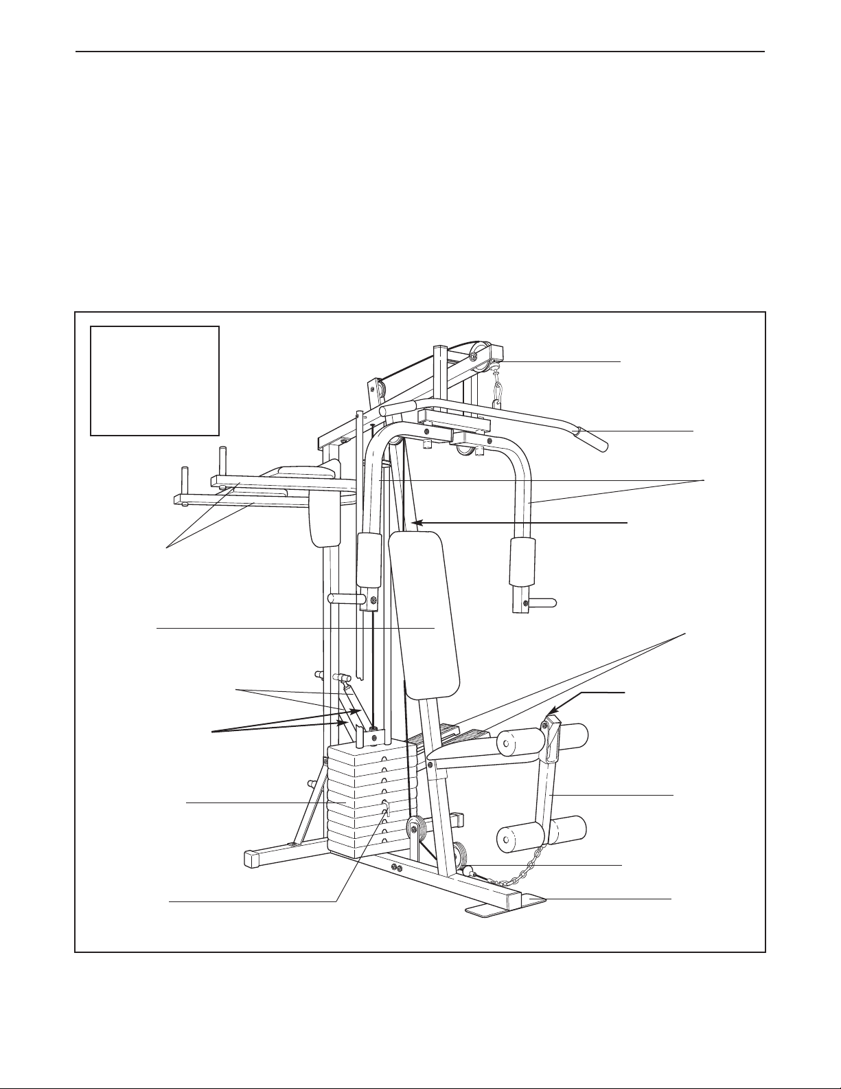
Before reading further, please review the drawing
below and familiarise yourself with the parts that are
labelled.
High Pulley Station
Lat Bar
Arms
VKR Arms
Backrest
Resistance Cylinders
Warning Decal 3
Weight Stack
Weight Pin
Warning Decal 1
Stepper
Warning Decal 2
Leg Lever
Low Pulley Station
Foot Plate
4

ASSEMBLY
Make Assembly Easier for Yourself
verything in this manual is designed to
E
ensure that the training system can be
assembled successfully by anyone. Before
beginning assembly, make sure to read the
information on this page; this brief introduction will save you much more time than
it takes to read it.
Assembly Requires Two Persons
For your convenience and safety, assemble the
training system with the help of another person.
Make sure you have the following tools:
Two adjustable wrenches
•
• One standard screwdriver
• One phillips screwdriver
• One rubber mallet
• You will also need grease or petroleum jelly, a
small amount of soapy water, and clear tape or
masking tape.
Note: Assembly will be more convenient if you have
a socket set, a set of open-end or closed-end
wrenches, or a set of ratchet wrenches.
Set Aside Enough Time
Due to the many features of the training system,
the assembly process will require a few hours. By
setting aside plenty of time and by deciding to
make the task enjoyable, assembly will go smoothly. You may want to assemble the training system
over a couple of evenings.
How to Orient Parts
As you assemble the training system, make sure
that all parts are oriented exactly as shown in the
drawings.
How to Identify Parts
To help you identify the small parts used in assembly, we have included a PART IDENTIFICATION
CHART in the center of this manual. Place the
chart on the floor and use it to easily identify parts
during each assembly step. Note: Some small
parts may have been pre-attached. If a part is
not in the parts bag, check to see if it has been
pre-attached.
How to Unpack the Box
Place all parts of the training system in a cleared
area and remove the packing materials. Do not dispose of the packing materials until assembly is completed.
Select a Location for the Training System
Because of its weight and size, the training system
should be assembled in the location where it will be
used. Make sure that there is enough room to walk
around the training system as you assemble it.
Tightening Parts
Tighten all parts as you assemble them, unless
instructed to do otherwise.
Questions?
If you have questions after reading the assembly
instructions, please call our Customer Service
Department at 0345-089009.
1. Before you begin, make sure that you have
carefully read the instructions at the top of
this page.
Press a 2” Inner Cap (27) into the Base (4).
Attach the Pulley Plate (20) to the Base (4) with
two 5/16” x 2 3/4” Bolts (11), two 5/16” Flat
Washers (8), and two 5/16” Nylon Locknuts (3).
Insert the two 5/16” x 2 1/2” Carriage Bolts (1) up
through the Base (4).
1
20
11
4
3
8
1
27
5
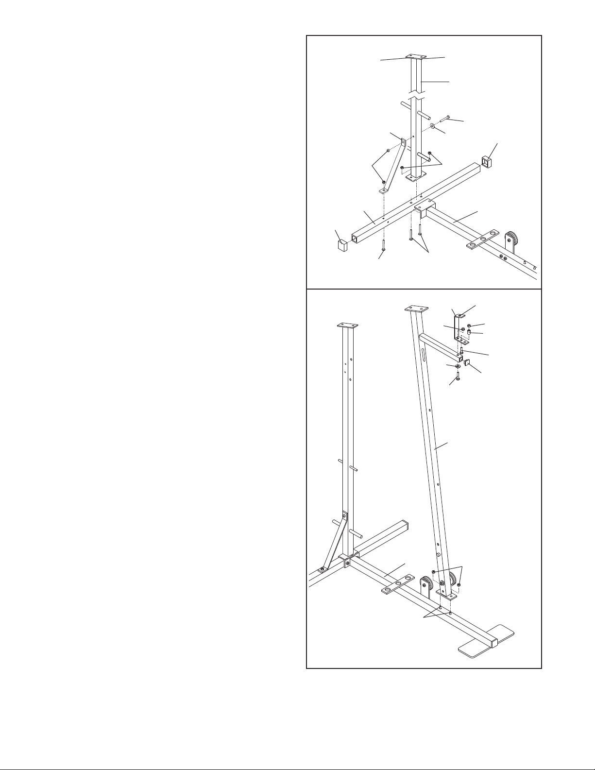
2. Press the two 2” Outer Caps (88) onto the
Stabiliser (5).
nsert two 5/16” x 2 3/4” Carriage Bolts (14) and
I
one 5/16” x 2 1/2” Carriage Bolt (1) up through the
tabiliser (5). Slide the end of the Base (4) and the
S
Rear Upright (82) onto the two 5/16” x 2 3/4”
Carriage Bolts. Make sure that the Rear Upright
is turned as shown. Thread 5/16” Nylon Locknuts
(3) onto the two Carriage Bolts. Do not tighten
the Nylon Locknuts yet.
Slide one end of the Brace (86) onto the 5/16” x
2 1/2” Carriage Bolt (1) in the Stabiliser (5). Thread
a 5/16” Nylon Locknut (3) onto the Carriage Bolt.
Do not tighten the Nylon Locknut yet.
Attach the other end of the Brace (86) to the Rear
Upright (82) with a 5/16” x 2 3/4” Bolt (11), a 5/16”
Flat Washer (8), and a 5/16” Nylon Locknut (3). Do
not tighten the Nylon Locknut yet.
2
Low Side
88
Bracket
82
86
3
5
1
14
11
8
3
88
4
3. Press the 1 1/4” Inner Cap (57) into the Front
Upright (42).
Attach the 1” Plastic Stop (64) to the centre hole
in the Stop Bracket (63) with a 5/16” x 1 1/2” Bolt
(24) and 5/16” Nylon Locknut (3).
Attach the Stop Bracket (63) to the Front Upright
(42) with a 5/16” x 2” Bolt (61), 5/16” Flat Washer
(8), and 5/16” Nylon Locknut (3).
Slide the Front Upright (42) onto the two 5/16” x
2 1/2” Carriage Bolts (1) in the Base (4). Thread
two 5/16” Nylon Locknuts (3) onto the Carriage
Bolts. Do not tighten the Nylon Locknuts yet.
3
4
63
3
8
61
Single Hole
3
64
24
57
42
3
1
6

4. Press two 2” Inner Caps (27) into the Top Frame
(67). Attach the Top Frame (67) to the Front
Upright (42) and to the Rear Upright (82) with two
/16” x 2 3/4” Bolts (11), 5/16” Flat Washers (8),
5
and 5/16” Nylon Locknuts (3). Do not tighten the
ylon Locknuts yet.
N
4
11
11
8
8
11
8
67
Attach the Top Frame (67) to the Stop Bracket
63) with a 5/16” x 2 3/4” Bolt (11), 5/16” Flat
(
Washer (8), and 5/16” Nylon Locknut (3). Do not
tighten the Nylon Locknut yet.
Tighten all Nylon Locknuts used in steps 2
through 4.
5. Press two 1 1/2” Bushings (93) into the Left Pedal
(90); press two 1 1/2” Bushings (93) into the
Right Pedal (89). Attach a Pedal Cover (92) to
each Pedal with a 1/2” Tap Screw (6).
Lubricate the pedal axles on the Rear Upright
(82). Slide the Right and Left Pedals (89, 90) onto
the right and left pedal axles. Note: Make sure
that the Pedals are on the correct sides; the
slotted brackets must be on the insides of the
Pedals. Hold a 1" Retainer (54) and 1" Round
Cover Cap (55) against the left pedal axle. The
teeth on the Retainer must bend toward the
Round Cover Cap. Tap the Retainer and Round
Cover Cap onto the pedal axle. Attach the Right
Pedal in the same manner.
6. Lubricate the cylinder axles on the Rear Upright
(82). Slide a 5/8” Spacer (97) and a Resistance
Cylinder (91) onto the right cylinder axle. Make
sure that the Spacer is turned as shown. Hold
a 5/8" Retainer (95) and 5/8" Round Cover Cap
(96) against the right cylinder axle. The teeth on
the Retainer must bend toward the Round
Cover Cap. Tap the Retainer and Round Cover
Cap onto the cylinder axle.
27
5
93
Lubricate
6
96
82
95
3
82
3
42
6
89
93
97
82—Lubricate
91
92
Slotted
Brackets
54
6
63
3
55
27
92
90
Attach a Resistance Cylinder (91) to the left cylinder axle in the same manner.
7. Raise the Left Pedal (90) and rest it on the hook
at the lower end of the left Resistance Cylinder
(91). The hook must be in one of the slots under
the Left Pedal.
Raise the Right Pedal (89) and rest it on the hook
at the lower end of the right Resistance Cylinder
(91). Make sure that the hooks are in the same
position under both Pedals.
7
89
91
Hooks
90
7
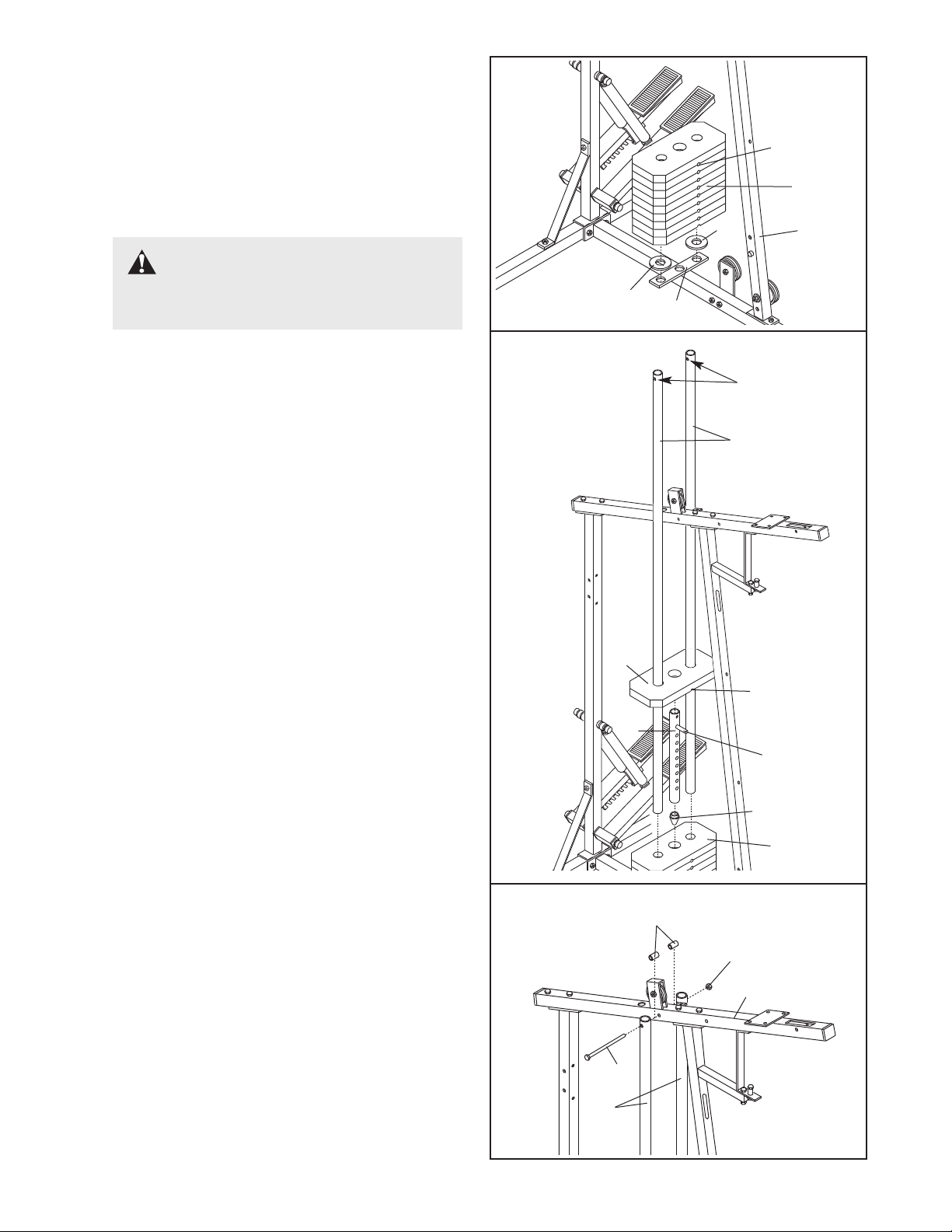
8. Set the two Weight Bumpers (19) on the indicated
plate on the Base (4). Align the holes in the
Weight Bumpers with the holes in the plate.
8
Stack nine Weights (25) on the Weight Bumpers
19). Each Weight must be turned so the pin
(
groove is facing the Front Upright (42). The
holes in the Weights must be aligned with the
holes in the Weight Bumpers.
CAUTION: Be careful to avoid
tipping the stack of Weights (25) until step
9 is completed.
9. Press the Weight Tube Endcap (79) into the indicated end of the Weight Tube (80).
Insert the Weight Tube (80) into the stack of
Weights (25). Slide the tenth Weight (25) onto the
upper end of the Weight Tube. The Weight Tube
must be turned so the welded pin is in the pin
groove in the Weight.
Locate the lower ends of the Weight Guides (72)
(there are holes near the upper ends). Insert the
lower ends of the Weight Guides into the ten
Weights (25).
Pin Groove
25
19
19
9
4
Upper ends of
Weight Guides
72
42
have holes
10. Attach the upper ends of the Weight Guides (72)
to the Top Frame (67) with the 5/16” x 6” Bolt
(74), the two 1/2” x 3/4” Bushings (73), and a
5/16” Nylon Locknut (3).
25
Pin Groove
80
Welded Pin
79
25
10
73
3
67
74
72
8
 Loading...