

Weslo WLEL93908.0 Owner's Manual
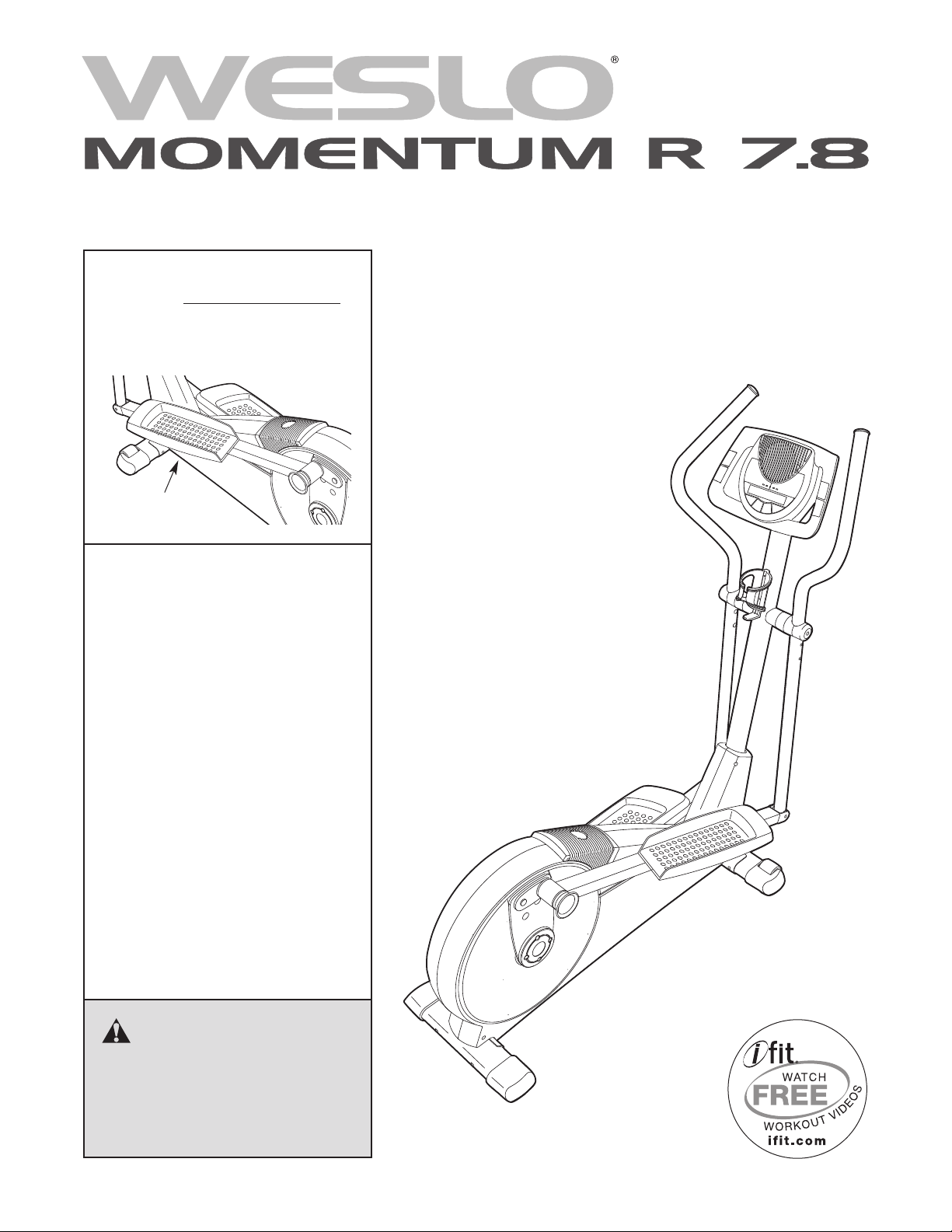
www.weslo.com
Model No. WLEL93908.0
Serial No.
Write the serial number in the
space above for future reference.
Serial Number
Decal
QUESTIONS?
As a manufacturer, we are committed to providing complete customer
satisfaction. If you have questions,
or if parts are damaged or missing,
DO NOT CONTACT THE STORE;
please contact Customer Care.
USERʼS MANUAL
IMPORTANT: You must note the
product model number and serial
number (see the drawing above)
before contacting us:
CALL TOLL-FREE:
1-866-699-3756
Mon.–Fri. 6 a.m.–6 p.m. MT
Sat. 8 a.m.–4 p.m. MT
ON THE WEB:
www.wesloservice.com
CAUTION
Read all precautions and instructions in this manual before using
this equipment. Keep this manual
for future reference.
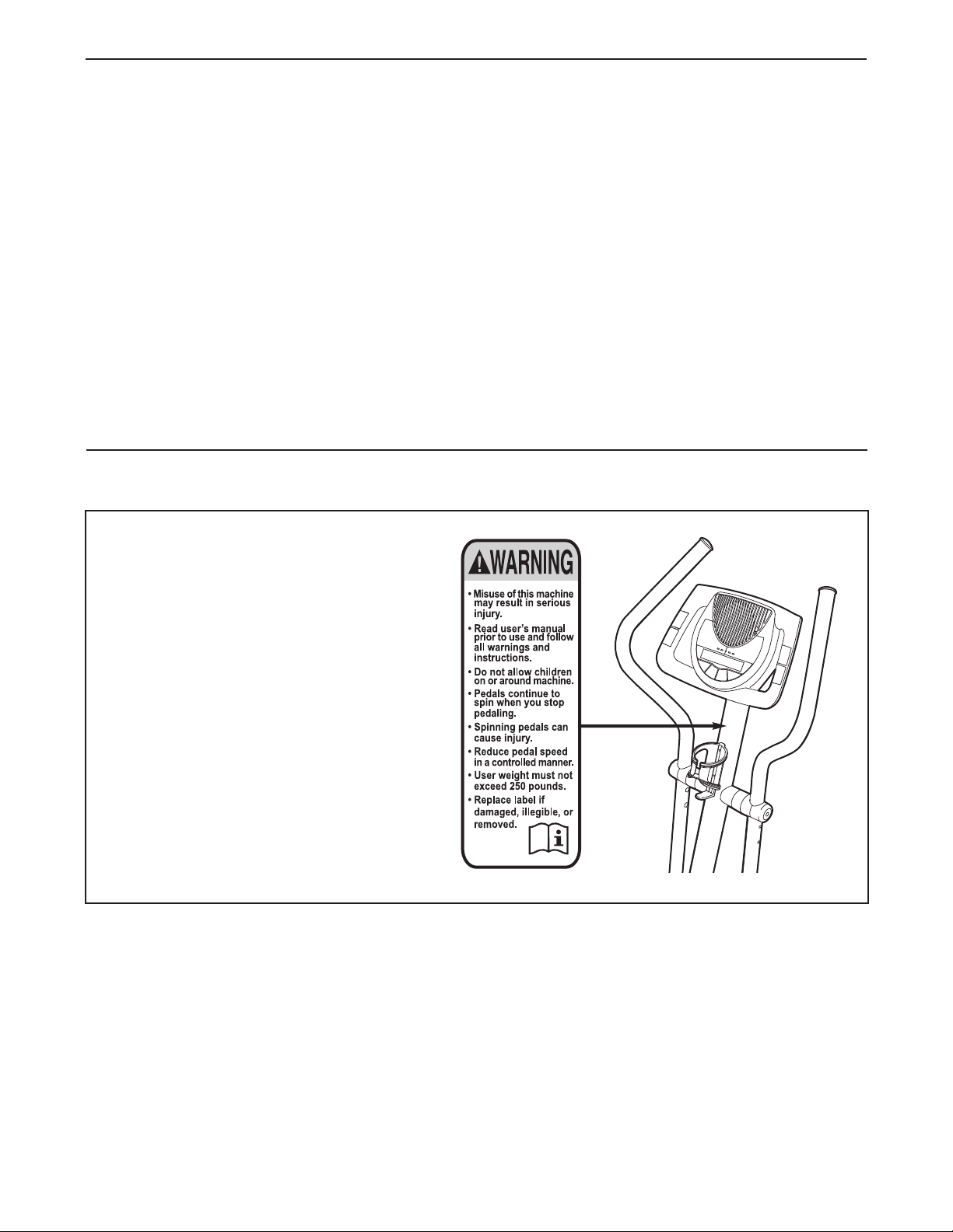
TABLE OF CONTENTS
ARNING DECAL PLACEMENT . . . . . . . . . . . . . . . . . . . . . . . . . . . . . . . . . . . . . . . . . . . . . . . . . . . . . . . . . . . . . .2
W
IMPORTANT PRECAUTIONS . . . . . . . . . . . . . . . . . . . . . . . . . . . . . . . . . . . . . . . . . . . . . . . . . . . . . . . . . . . . . . . .3
BEFORE YOU BEGIN . . . . . . . . . . . . . . . . . . . . . . . . . . . . . . . . . . . . . . . . . . . . . . . . . . . . . . . . . . . . . . . . . . . . . .4
ASSEMBLY . . . . . . . . . . . . . . . . . . . . . . . . . . . . . . . . . . . . . . . . . . . . . . . . . . . . . . . . . . . . . . . . . . . . . . . . . . . . . . .5
HOW TO USE THE ELLIPTICAL EXERCISER . . . . . . . . . . . . . . . . . . . . . . . . . . . . . . . . . . . . . . . . . . . . . . . . . .10
AINTENANCE AND TROUBLESHOOTING . . . . . . . . . . . . . . . . . . . . . . . . . . . . . . . . . . . . . . . . . . . . . . . . . . .18
M
EXERCISE GUIDELINES . . . . . . . . . . . . . . . . . . . . . . . . . . . . . . . . . . . . . . . . . . . . . . . . . . . . . . . . . . . . . . . . . . .19
PART LIST . . . . . . . . . . . . . . . . . . . . . . . . . . . . . . . . . . . . . . . . . . . . . . . . . . . . . . . . . . . . . . . . . . . . . . . . . . . . . .20
EXPLODED DRAWING . . . . . . . . . . . . . . . . . . . . . . . . . . . . . . . . . . . . . . . . . . . . . . . . . . . . . . . . . . . . . . . . . . . .22
ORDERING REPLACEMENT PARTS . . . . . . . . . . . . . . . . . . . . . . . . . . . . . . . . . . . . . . . . . . . . . . . . . .Back Cover
LIMITED WARRANTY . . . . . . . . . . . . . . . . . . . . . . . . . . . . . . . . . . . . . . . . . . . . . . . . . . . . . . . . . . . . . .Back Cover
WARNING DECAL PLACEMENT
This drawing shows the location(s) of the
warning decal(s). If a decal is missing or
illegible, see the front cover of this
manual and request a free replacement
decal. Apply the decal in the location
shown. Note: The decal(s) may not be
shown at actual size.
WESLO is a registered trademark of ICON IP, Inc.
2

IMPORTANT PRECAUTIONS
WARNING: To reduce the risk of serious injury, read all important precautions and
instructions in this manual and all warnings on your elliptical exerciser before using your elliptical
exerciser. ICON assumes no responsibility for personal injury or property damage sustained by or
hrough the use of this product.
t
1. Before beginning any exercise program,
consult your physician. This is especially
important for persons over the age of 35 or
persons with pre-existing health problems.
2. It is the responsibility of the owner to ensure
that all users of the elliptical exerciser are
adequately informed of all precautions.
3. The elliptical exerciser is intended for home
use only. Do not use the elliptical exerciser
in a commercial, rental, or institutional setting.
4. Keep the elliptical exerciser indoors, away
from moisture and dust. Place the elliptical
exerciser on a level surface, with a mat
beneath it to protect the floor or carpet.
Make sure that there is at least 3 ft. (1 m) of
clearance in the front and rear of your elliptical exerciser and 2 ft. (0.6 m) on each side.
5. Inspect and properly tighten all parts regularly. Replace any worn parts immediately.
8. Wear appropriate exercise clothes while
exercising; do not wear loose clothes that
could become caught on the elliptical exerciser. Always wear athletic shoes for foot
protection.
9. Hold the handlebars while mounting, dismounting, or using the elliptical exerciser.
10. Keep your back straight while using the elliptical exerciser; do not arch your back.
11. The pulse sensor is not a medical device.
Various factors, including the userʼs movement, may affect the accuracy of heart rate
readings. The pulse sensor is intended only
as an exercise aid in determining heart rate
trends in general.
12. When you stop exercising, allow the pedals
to slowly come to a stop.
13. If you feel pain or dizziness while exercising,
stop immediately and cool down.
6. Keep children under age 12 and pets away
from the elliptical exerciser at all times.
7. The elliptical exerciser should not be used
by persons weighing more than 250 lbs.
(113 kg).
14. Use the elliptical exerciser only as described
in this manual.
3
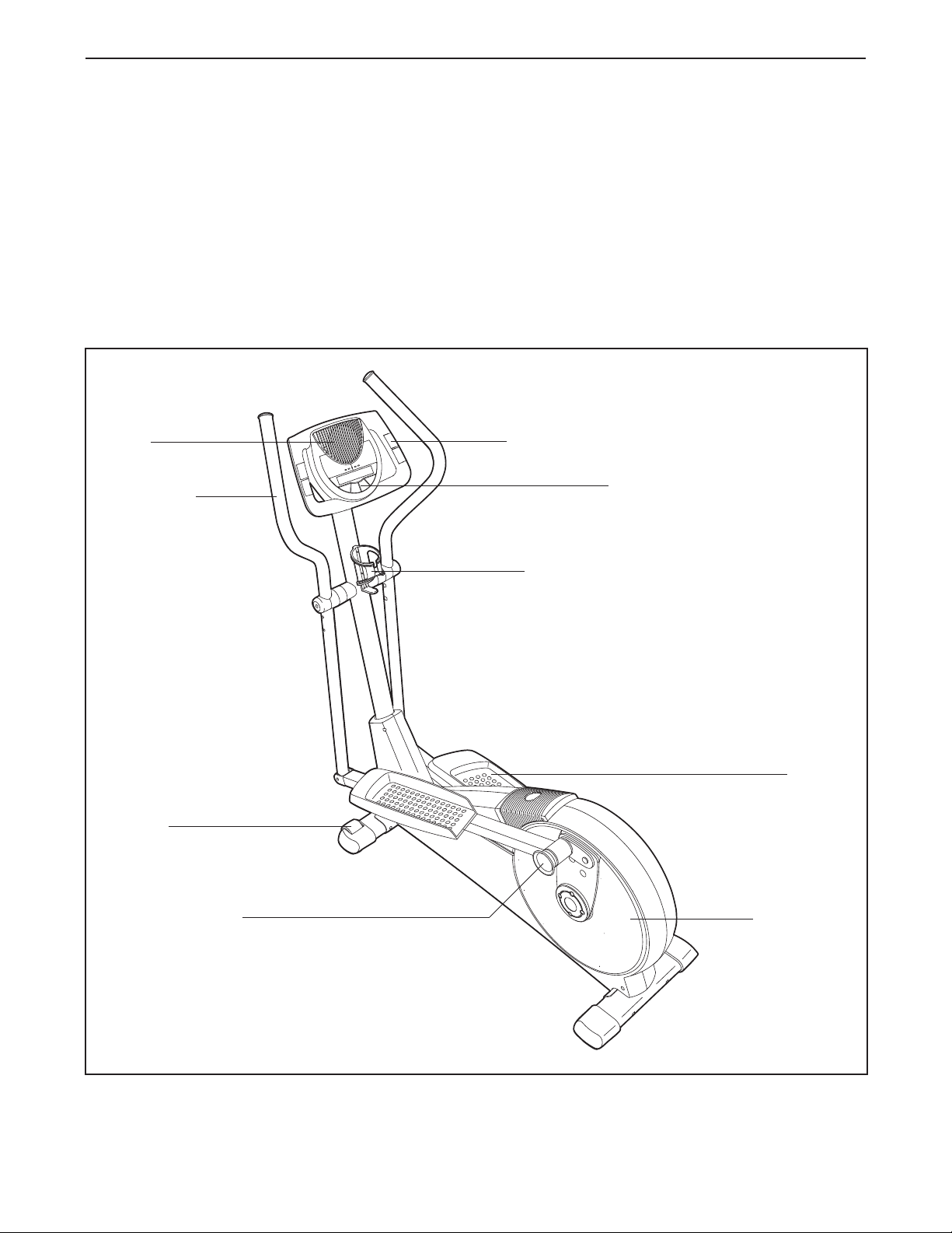
BEFORE YOU BEGIN
Congratulations for selecting the new WESLO
MOMENTUM R 7.8 elliptical exerciser. The MOMEN-
UM R 7.8 is a smooth exerciser that moves your feet
T
in a natural elliptical path, minimizing the impact on
your knees and ankles.
For your benefit, read this manual carefully before
you use the elliptical exerciser. If you have ques-
tions after reading this manual, please see the front
cover of this manual. To help us assist you, note the
product model number and serial number before con-
Fan
Handlebar
®
tacting us. The model number and the location of the
serial number decal are shown on the front cover of
his manual.
t
To avoid a registration fee for any service needed
under warranty, you must register the elliptical
exerciser at www.wesloservice.com/registration.
Before reading further, please familiarize yourself with
the parts that are labeled in the drawing below.
Handgrip Pulse Sensor
Console
Wheel
Adjustment Knob
Water Bottle Holder*
Pedal
Pedal Disc
*Water bottle is not included
4
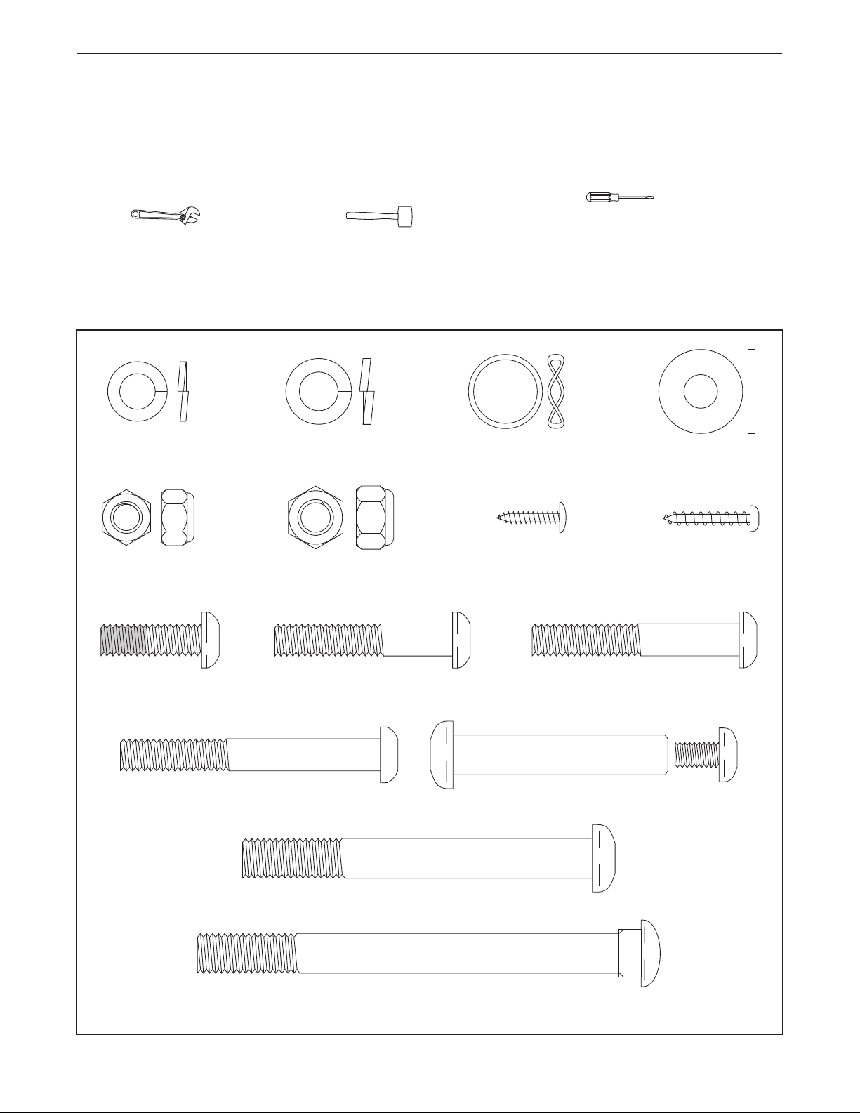
M10 x 112mm Carriage Bolt (34)–4
M10 x 88mm Button Screw (63)–2
M10 x 52mm Bolt Set (27)–2
M8 x 65mm Button Screw (99)–4
M10 Split
Washer (70)–2
M8 Large
Washer (53)–10
Wave Washer
(95)–2
M8 Split
Washer (100)–4
M8 x 25mm Patch
Screw (22)–2
M8 x 50mm Button
Screw (89)–4
M8 x 45mm Button
Bolt (50)–4
M10 Locknut
(29)–4
M8 Locknut
(46)–8
M4 x 16mm
Screw (66)–4
M4 x 22mm
Screw (91)–2
ASSEMBLY
To hire an authorized service technician to assemble the elliptical exerciser, call 1-800-445-2480.
Assembly requires two persons. Place all parts of the elliptical exerciser in a cleared area and remove the
packing materials. Do not dispose of the packing materials until assembly is completed.
n addition to the included tool(s), assembly requires a Phillips screwdriver , an adjustable
I
wrench , and a rubber mallet .
As you assemble the elliptical exerciser, use the drawings below to identify small parts. The number in parentheses below each drawing is the key number of the part, from the PART LIST near the end of this manual. The
number following the parentheses is the quantity needed for assembly. Note: Some small parts may have
been preassembled. If a part is not in the hardware kit, check to see if it has been preassembled.
5
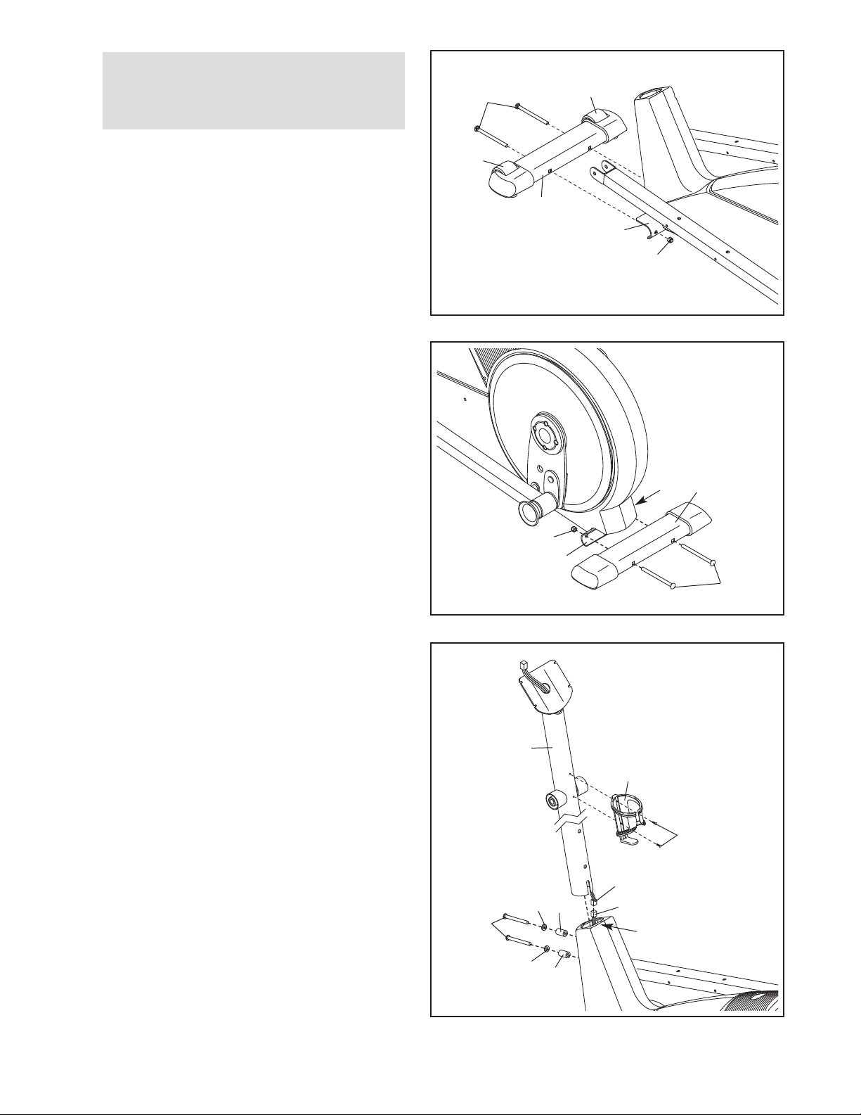
1.
To make assembly easier, read the
information on page 5 before you begin
assembling the elliptical exerciser.
1
34
32
Identify the Front Stabilizer (3), which has
Wheels (32) attached. Orient the Front
Stabilizer so that the Wheels are not touching
the floor.
While a second person lifts the front of the
Frame (1), attach the Front Stabilizer (3) to the
Frame with two M10 x 112mm Carriage Bolts
(34) and two M10 Locknuts (29).
2. While another person lifts the back of the
Frame (1), attach the Rear Stabilizer (4) to the
Frame with two M10 x 112mm Carriage Bolts
(34) and two M10 Locknuts (29).
32
3
1
29
2
29
4
29
1
3. While a second person holds the Upright (2)
near the Frame (1), connect the Upper Wire
Harness (86) to the Lower Wire Harness (87).
Tip: Avoid pinching the Wire Harnesses (86,
87). Insert the Upright (2) into the Frame (1).
Slide an M10 Split Washer (70) and a Frame
Spacer (83) onto each of the two M10 x 88mm
Button Screws (63). Insert the Button Screws
into the Frame (1) and the Upright (2). Make
sure that the concave ends of the Frame
Spacers are facing the Frame. Do not tighten
the Button Screws yet.
Attach the Water Bottle Holder (105) to the
Upright (2) with two M4 x 22mm Screws (91).
34
3
Avoid pinching
the wires
2
105
91
86
70
63
70
83
83
87
1
6
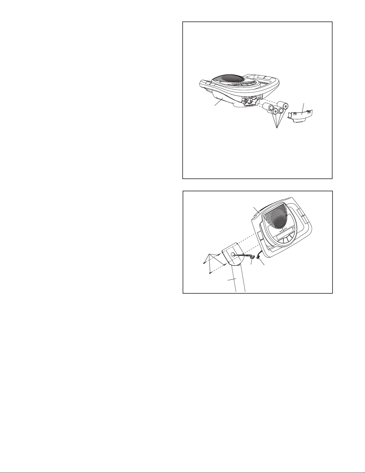
4. The Console (5) can use four 1.5V D batteries
not included); alkaline batteries are recom-
(
mended. IMPORTANT: If the Console has
been exposed to cold temperatures, allow it
to warm to room temperature before insert-
ng batteries. Otherwise, you may damage
i
the console displays or other electronic
components. Remove the battery cover, insert
the batteries into the battery compartment, and
reattach the battery cover. Make sure to orient
the batteries as shown by the diagram
inside the battery compartment.
To purchase an optional AC adapter, contact
the store where you purchased this product
or call the telephone number on the cover of
this manual. To avoid damaging the console,
use only a manufacturer-supplied AC
adapter. Plug one end of the AC adapter into
the jack on the console; plug the other end into
an outlet installed in accordance with all local
codes and ordinances.
4
Battery
Cover
5
Batteries
5. While a second person holds the Console (5)
near the Upright (2), connect the console wire
harness to the Upper Wire Harness (86).
Insert the excess wire harness into the Upright
(2).
Tip: Avoid pinching the wires. Attach the
Console (5) to the Upright (2) with four M4 x
16mm Screws (66).
5
Avoid pinching
the wires
66
5
86
Wire
2
Harness
7
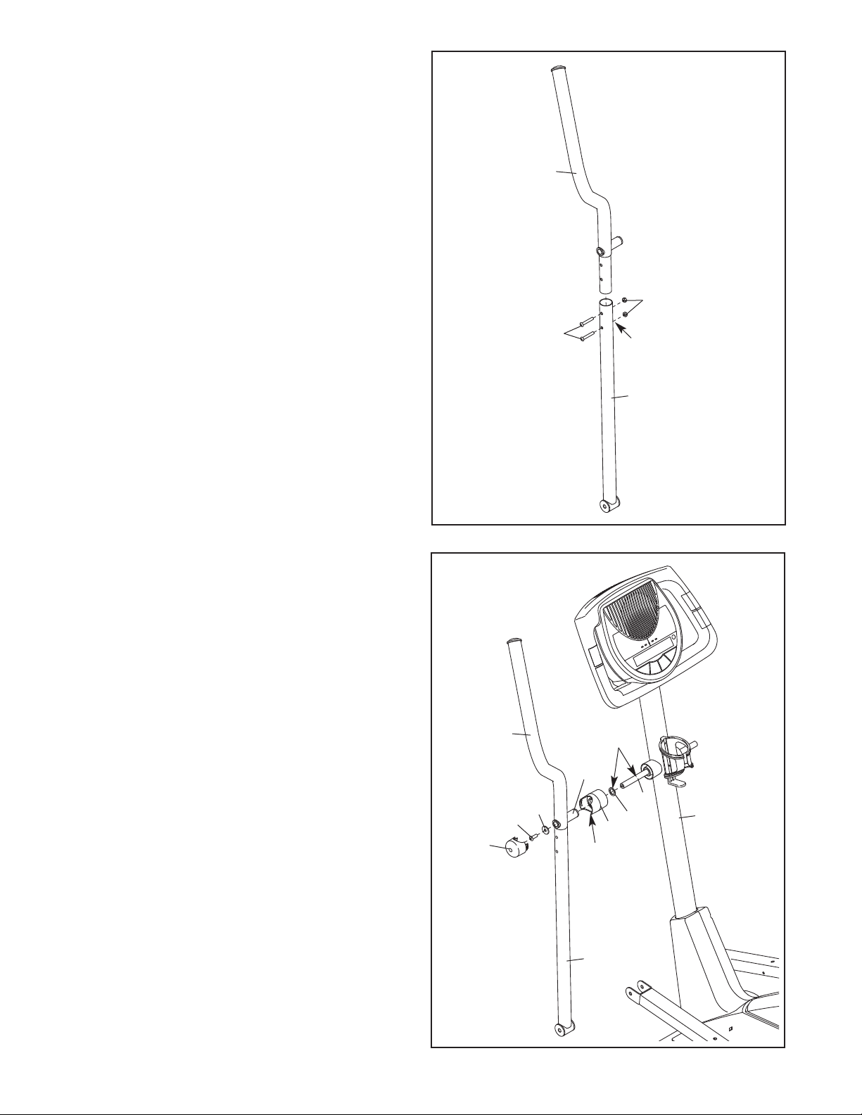
6. Identify the Left Handlebar (9), which is marked
with an “L” sticker.
nsert the Left Handlebar (9) into one of the
I
Handlebar Legs (79). Make sure that the
exagonal holes are in the indicated loca-
h
tion.
Attach the Left Handlebar (9) to the Handlebar
Leg (79) with two M8 x 45mm Button Bolts (50)
and two M8 Locknuts (46). Make sure that the
Locknuts are inside the hexagonal holes. Do
not tighten the Button Bolts yet.
6
9
Repeat this step for the Right Handlebar (not
shown) and the other Handlebar Leg (not
shown).
7. Apply a generous amount of the included
grease to the Pivot Axle (97) and to two Wave
Washers (95).
Insert the Pivot Axle (97) into the Upright (2)
and center it.
Slide a Waver Washer (95) onto the left side of
the Pivot Axle (97).
46
50
7
Hexagonal
Holes
79
Slide a Handlebar Spacer (25) onto the short
tube on the Left Handlebar (9). Rotate the
Handlebar Spacer so that the small arrow
points toward the floor.
Slide the Left Handlebar (9) onto the left end of
the Pivot Axle (97). Finger tighten an M8 x
25mm Patch Screw (22) and an M8 Large
Washer (53) into the end of the Pivot Axle.
Attach a Handlebar Cap (23) by pressing its
small tabs into the Handlebar Spacer (25).
Assemble the Right Handlebar (not shown)
in the same way.
Tighten both M8 x 25mm Patch Screws (22)
at the same time.
9
53
22
23
Grease
Tube
Arrow
79
25
95
97
2
8
 Loading...