

Model No. WETL2614.0
Serial No.
Serial
Number
Decal
QUESTIONS?
As a manufacturer, we are committed to providing complete
customer satisfaction. If you
have questions, or if there are
missing or damaged parts,
please call:
08457 089 009
USER'S MANUAL
or write:
ICON Health & Fitness, Ltd.
Customer Service Department
Unit 4
Revie Road Industrial Estate
Revie Road
Beeston
Leeds, LS118JG
UK
email: csuk@iconeurope.com
CAUTION
Read all precautions and instructions in this manual before
using this equipment. Save this
manual for future reference.
Class HC Fitness Product

TABLE OF CONTENTS
IMPORTANT PRECAUTIONS . . . . . . . . . . . . . . . . . . . . . . . . . . . . . . . . . . . . . . . . . . . . . . . . . . . . . . . . . . . . . . . .3
BEFORE YOU BEGIN . . . . . . . . . . . . . . . . . . . . . . . . . . . . . . . . . . . . . . . . . . . . . . . . . . . . . . . . . . . . . . . . . . . . . .5
ASSEMBLY . . . . . . . . . . . . . . . . . . . . . . . . . . . . . . . . . . . . . . . . . . . . . . . . . . . . . . . . . . . . . . . . . . . . . . . . . . . . . . .6
OPERATION AND ADJUSTMENT . . . . . . . . . . . . . . . . . . . . . . . . . . . . . . . . . . . . . . . . . . . . . . . . . . . . . . . . . . . . .9
HOW TO FOLD AND MOVE THE TREADMILL . . . . . . . . . . . . . . . . . . . . . . . . . . . . . . . . . . . . . . . . . . . . . . . . . .14
TROUBLESHOOTING . . . . . . . . . . . . . . . . . . . . . . . . . . . . . . . . . . . . . . . . . . . . . . . . . . . . . . . . . . . . . . . . . . . . .16
CONDITIONING GUIDELINES . . . . . . . . . . . . . . . . . . . . . . . . . . . . . . . . . . . . . . . . . . . . . . . . . . . . . . . . . . . . . . .18
ORDERING REPLACEMENT PARTS . . . . . . . . . . . . . . . . . . . . . . . . . . . . . . . . . . . . . . . . . . . . . . . . . .Back Cover
Note: An EXPLODED DRAWING and a PART LIST are attached in the centre of this manual.
WESLO is a registered trademark of ICON IP, Inc.
2

IMPORTANT PRECAUTIONS
WARNING: T
following important precautions and information before operating the treadmill.
1. It is the responsibility of the owner to ensure
that all users of this treadmill are adequately
informed of all warnings and precautions.
2. Use the treadmill only as described.
3. Keep the treadmill indoors, away from moisture and dust. Do not put the treadmill in a
garage or covered patio, or near water.
4. Place the treadmill on a level surface, with at
least 2.5 m (8 ft.) of clearance behind it and
0.5 m (2 ft.) on each side. Do not place the
treadmill on a surface that blocks any air
openings. To protect the floor or carpet from
damage, place a mat under the treadmill.
5. Do not operate the treadmill where aerosol
products are used or where oxygen is being
administered.
6. Keep children under the age of 12 and pets
away from the treadmill at all times.
7. The treadmill should be used only by persons
weighing 115 kg (250 lbs.) or less.
8. Never allow more than one person on the
treadmill at a time.
o reduce the risk of burns, fire, electric shock, or injury to persons, read the
No other appliance should be on the same circuit. When replacing the fuse, an ASTA approved BS1362 type should be fitted to the
fuse carrier. A 13 amp fuse should be used.
12. If an extension cord is needed, use only a 3conductor, 1mm
longer than 1.5 m.
13. Keep the power cord away from heated
surfaces.
14. Do not change the incline of the treadmill by
placing objects under the treadmill.
15. Never move the walking belt whilst the power
is turned off. Do not operate the treadmill if
the power cord or plug is damaged, or if the
treadmill is not working properly. (See BEFORE YOU BEGIN on page 5 if the treadmill is
not working properly.)
16. Never start the treadmill whilst you are standing on the walking belt. Always hold the
handrails whilst using the treadmill.
17. The treadmill is capable of high speeds.
Adjust the speed in small increments to avoid
sudden jumps in speed.
2
(14-gauge) cord that is no
Wear appropriate exercise clothes when
9.
using the treadmill. Do not wear loose clothes
that could become caught in the treadmill.
Athletic support clothes are recommended for
both men and women.
Always wear athletic
shoes. Never use the treadmill with bare feet,
wearing only stockings, or in sandals.
10. Do not attempt to raise, lower, or move the
treadmill until it is properly assembled. (See
ASSEMBLY on page 6, and HOW TO FOLD
AND MOVE THE TREADMILL on page 14.)
You must be able to safely lift 20 kg (45 lbs) to
raise, lower, or move the treadmill.
11. When connecting the power cord (see page 9),
plug the power cord into an earthed circuit.
The pulse sensor is not a medical device.
18.
Various factors, including the user’s movement, may affect the accuracy of heart rate
readings. The pulse sensor is intended only as
an exercise aid in determining heart rate
trends in general.
19. Never leave the treadmill unattended whilst it
is running. Always remove the key, unplug
the power cord, and move the on/off switch to
the off position when the treadmill is not in
use. (See the drawing on page 5 for the location of the on/off switch.)
20.
When folding or moving the treadmill, make
sure that the storage latch is fully closed.
3
21. Inspect and properly tighten all parts of the
readmill regularly.
t
22. Never insert any object into any opening.
23.
DANGER: Always unplug the power
cord immediately after use, before cleaning the
treadmill, and before performing the maintenance and adjustment procedures described in
this manual. Never remove the motor hood un-
ess instructed to do so by an authorised ser-
l
vice representative. Servicing other than the
procedures in this manual should be performed
y an authorised service representative only.
b
24. The treadmill is intended for in-home use
nly. Do not use the treadmill in a commer-
o
cial, rental, or institutional setting.
WARNING: Before beginning this or any exercise program, consult your physician. This
is especially important for persons over the age of 35 or persons with pre-existing health problems.
Read all instructions before using. ICON assumes no responsibility for personal injury or property
damage sustained by or through the use of this product.
SAVE THESE INSTRUCTIONS
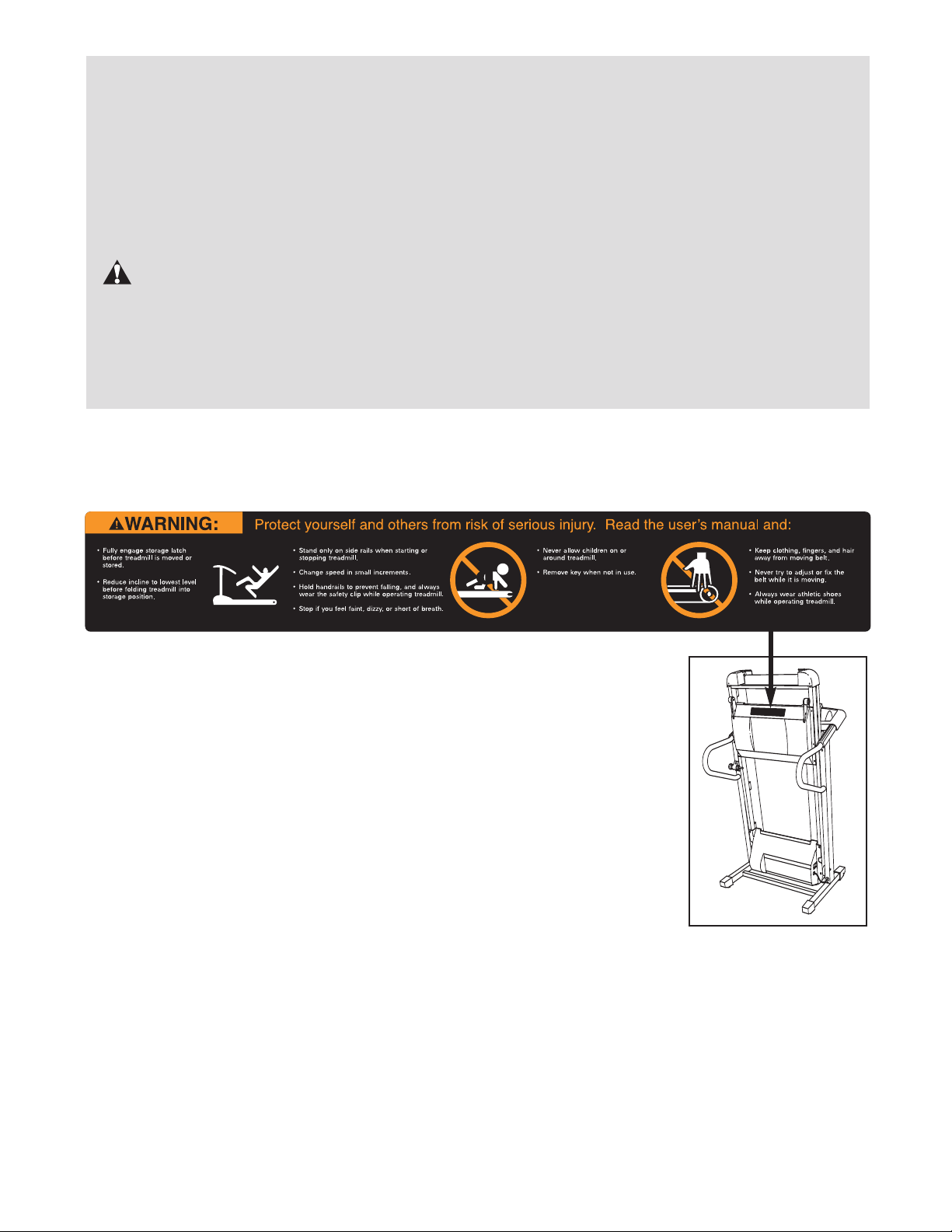
The decal shown below has been placed on the treadmill. If the decal is missing, or if it is not legible, call
our Customer Service Department and order a free replacement decal (see the back cover of this manual). Apply the decal in the location shown. Note: The decal may not be shown at actual size.
4
BEFORE YOU BEGIN
hank you for selecting the new WESLO
T
5 treadmill. The CADENCE 85 treadmill combines ad-
8
vanced technology with innovative design to help you
get the most from your exercise in the privacy of your
home. And when you’re not exercising, the unique CADENCE 85 treadmill can be folded up, requiring less
than half the floor space of other treadmills.
For your benefit, read this manual carefully before
using the treadmill. If you have questions after read-
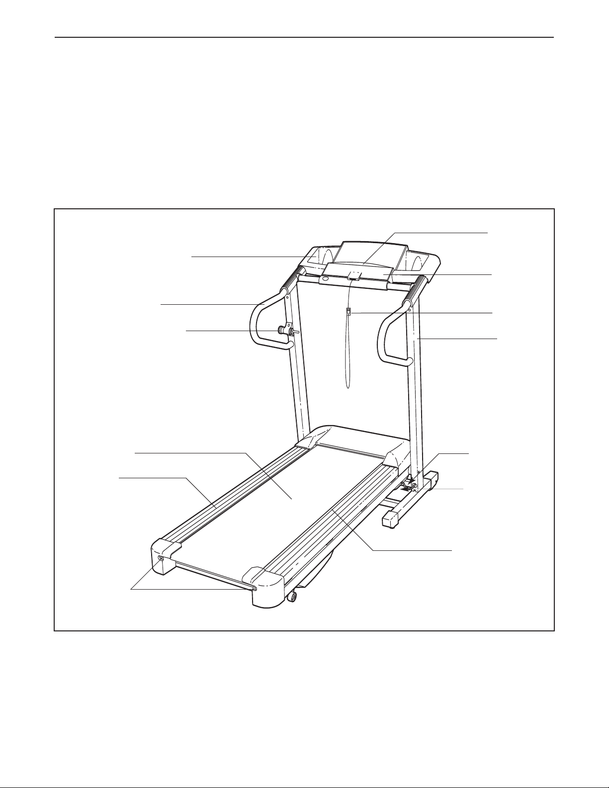
Accessory Tray
Handrail
Storage Latch
®
ADENCE
C
ng this manual, please call our Customer Service
i
epartment at
D
please note the product model number and serial number before calling. The model number of the treadmill
is WETL2614.0. The serial number can be found on a
decal attached to the treadmill (see the front cover of
this manual for the location).
Before reading further, please familiarise yourself with
the parts that are labelled in the drawing below.
8457 089 009.To help us assist you,
0
Bookrack
Console
Key/Clip
Upright
Walking Belt
Foot Rail
BACK
Rear Roller
Adjustment Bolts
RIGHT SIDE
On/Off Switch
Circuit Breaker
Walking Platform
5
ASSEMBLY
ssembly requires two persons.Set the treadmill in a cleared area and remove all packing materials. Do not
A
dispose of the packing materials until assembly is completed. Note: The underside of the treadmill walking belt is
coated with high-performance lubricant. During shipping, a small amount of lubricant may be transferred to the
top of the walking belt or the shipping carton. This is a normal condition and does not affect treadmill performance. If there is lubricant on top of the walking belt, simply wipe off the lubricant with a soft cloth and a mild,
non-abrasive cleaner.
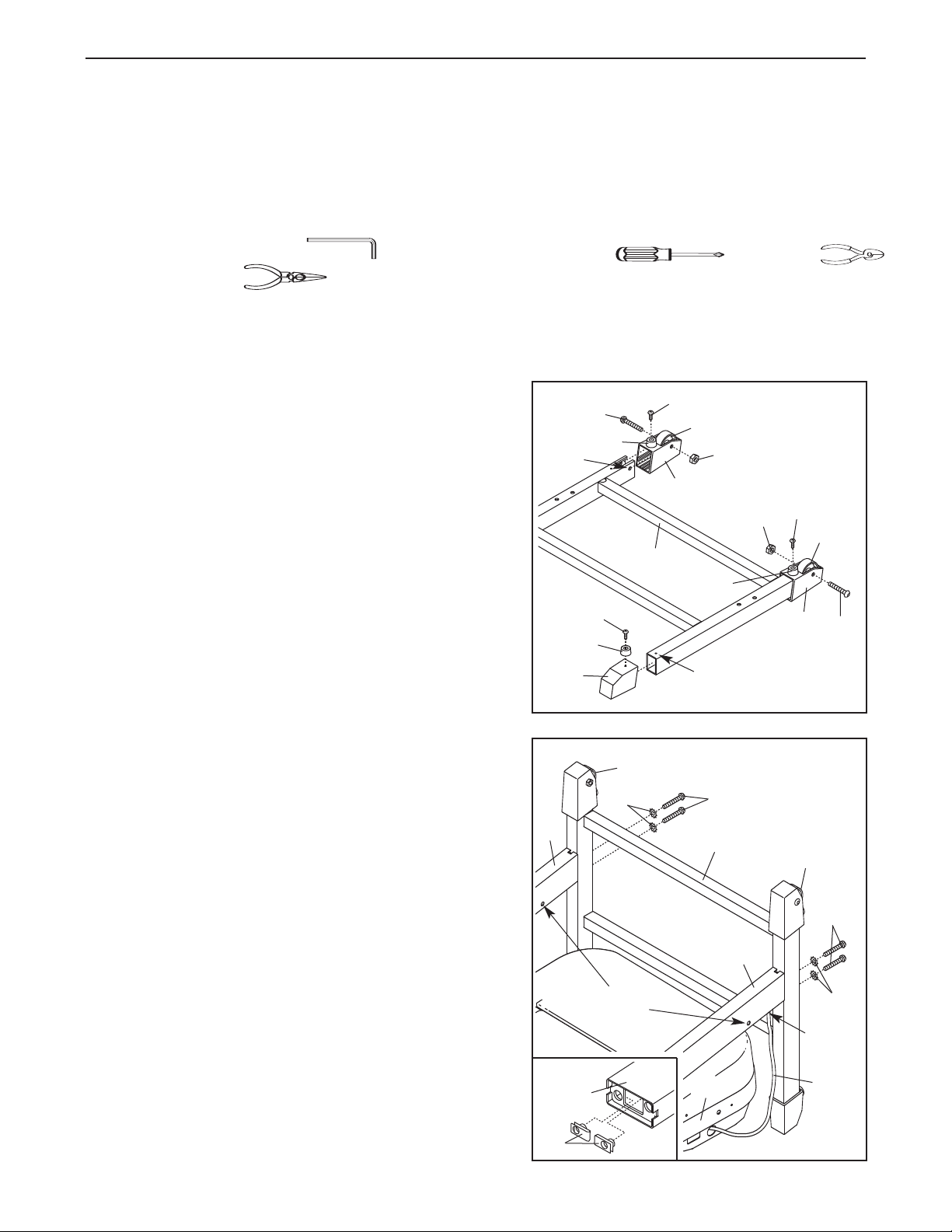
Assembly requires the included hex keys and your own phillips screwdriver , wire cutters
and needlenose pliers .
For help identifying the assembly hardware, see the PART IDENTIFICATION CHART in the centre of this
manual. Note: The assembly hardware and other small parts are packaged in separate part bags. Do not
open the part bags until instructed to do so.
1. Make sure that the power cord is unplugged.
Place the Base (79) in the position shown, with the indicated small holes on top (only one small hole is shown).
Place a Wheel (63) in each Wheel Housing (62), and
slide the Wheel Housings onto the ends of the Base that
have bolt holes.
Open part bag A. Attach the Wheels (63) to the Wheel
Housings (62) with 2 1/2” Bolts (61) and Wheel Nuts
(64). Make sure that the Wheel Nuts are on the sides
shown; do not overtighten the Bolts.
Slide the two Base Endcaps (75) onto the other ends of
the Base (79) (only one Base Endcap is shown). Attach
the four Base Pads (73) to the Base Endcaps and the
Wheel Housings (62) with four 1 1/4” Tek Screws (60).
2. Raise the Base (79) to a vertical position, and hold it
near the treadmill Frame (96) as shown. Make sure that
the Wheels (63) are in the indicated position.
Identify the Right Upright (104), which has a large round
hole in the indicated location. Feed the Wire Harness
(65) into the hole and out of the top of the Right Upright.
Make sure that there are two U-nuts (74) in the lower
end of the Right Upright (see drawing 2a). Hold
Upright against the Base (79) as shown. Make sure that
the Right Upright is oriented so the pivot hole is in the
position shown. Hand tighten two 3” Bolts (58) with two
5/16” Star Washers (57) into the bottom of the Base and
the lower end of the Right Upright.
Attach the Left Upright (47) to the Base (79) in the same
way. Note: There is not a wire harness on the left side.
With the help of a second person, raise the Uprights (47,
104) to a vertical position.
the Right
1
Bolt
Hole
2
47
2a
75
104
60
73
61
73
63
57
Pivot
Holes
79
60
63
62
Small Hole
96
73
58
79
64
104
64
60
62
63
63
61
58
57
Round
Hole
65
74
6
3. Open part bag B. Hold an Upright Spacer (59) against
one side of the Frame (96) as shown. Insert a 3 1/2” Bolt
54) into the indicated hole in the Upright Spacer and the
(
Frame. Next, tighten a Crossbar Screw (37) into the
pright Spacer and the Frame. Then, remove the 3 1/2”
U
Bolt. Repeat this procedure on the other side of the
Frame.
Have a second person lift the front end of the Frame
(96). Insert a 3 1/2” Bolt (54) with a 3/8” Star Washer (55)
into the Right Upright (104) and the right Upright Spacer
(59), and tighten the Bolt into the Frame.
tighten the Bolt.
of the Frame.
Repeat this procedure on the left side
Do not over-
3
37
96
59
Hole
104
5
5
54
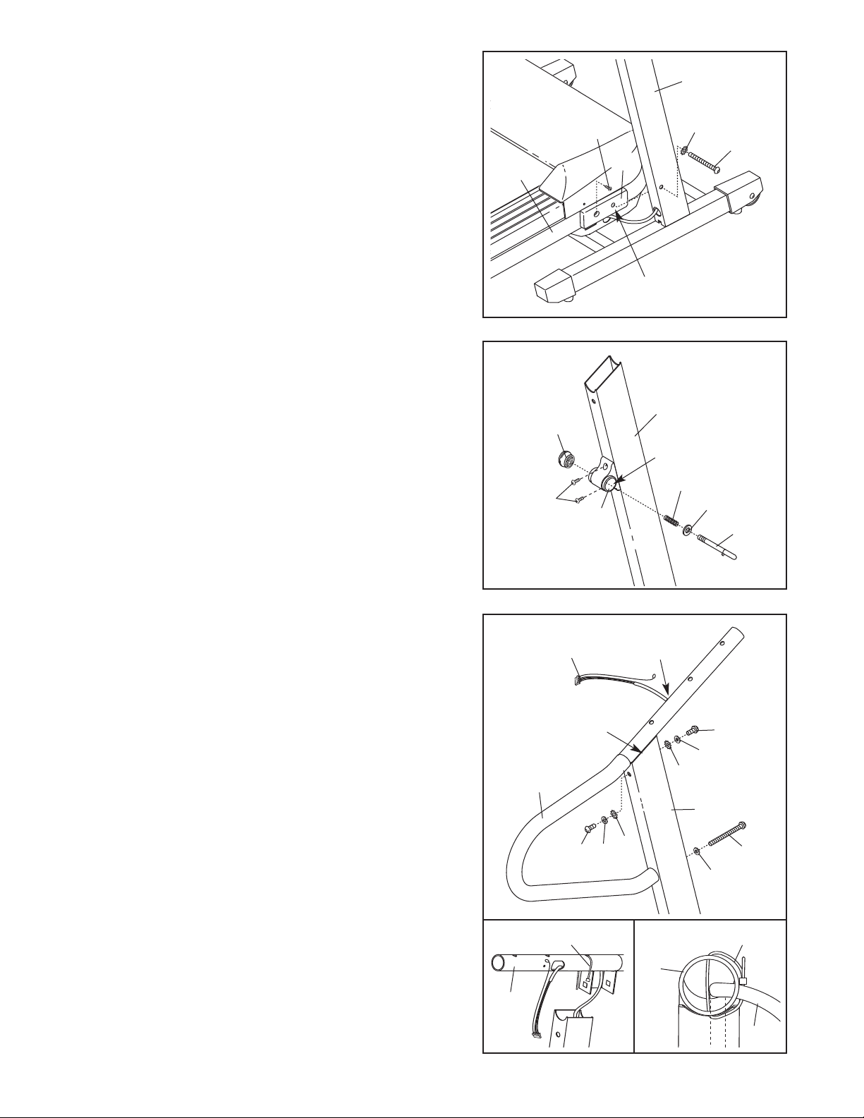
4. Attach the Latch Housing (46) to the Left Upright (47)
with two 3/4” Screws (38).
hole in the Latch Housing is on the side shown.
Remove the knob from the pin. Make sure that the collar and the spring are on the pin. Insert the pin into the
Storage Latch (46), and then tighten the knob back onto
the pin.
5. Feed the Wire Harness (65) up into the bracket on one of
the Handrails (40) and out of the large hole in the left
side. (Note: It may be helpful to use needlenose pliers to
pull the Wire Harness out of the hole.) Remove any nylon
ties from the bracket.
Insert the bracket on the Handrail (40) into the upper end
of the Right Upright (104). Attach the Handrail with two 1”
Bolts (43), two 1/4” Washers (44), two 1/4” Star Washers
(45), a 4” Bolt (117), and a 5/16” Washer (122) as
shown. Do not tighten the Bolts yet.
See drawing 5a. Insert the included nylon tie through the
indicated hole in the Handrail (40). See drawing 5b. Look
into the Handrail and make sure that the Wire Harness
(65) is secured to the side shown. Tighten the nylon tie
and cut the excess off the end.
Make sure that the large
4
47
Knob
Large Hole
Spring
38
46
5
65
Bracket
40
44
43
Large
Hole
45
Collar
Pin
43
44
45
104
117
122
Attach the other Handrail (not shown) in the same way.
Note: You may need to tip the Handrail to one side as
you insert the bracket. There is not a wire harness in the
left Upright (not shown).
7
5a
40
Tie
5b
40
Tie
65
 Loading...