

Page 1
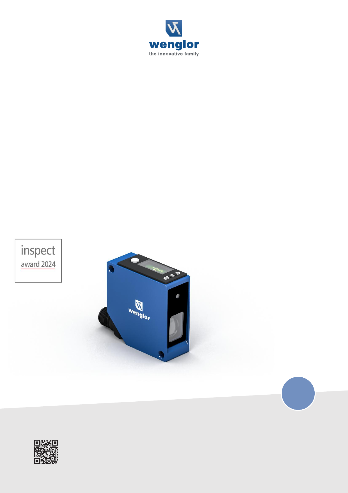
Operating Instructions
P3PC341
Laser Distance Sensor Triangulation
Translation of the original operating instructions
Subject to change without notice
Available as PDF file only
Version 2.3
www.wenglor.com
EN
Page 2

Table of Contents | P3PC341 ‒ Laser Distance Sensor Triangulation 2
Table of Contents
1 General ........................................................................................................................................................................... 4
1.1 Information Concerning these Instructions ...................................................................................................................... 4
1.2 Explanation of Symbols ....................................................................................................................................................... 4
1.3 Limitation of Liability ............................................................................................................................................................. 5
1.4 Copyrights .............................................................................................................................................................................. 5
2 For Your Safety .............................................................................................................................................................. 6
2.1 Use for Intended Purpose ................................................................................................................................................... 6
2.2 Use for Other than the Intended Purpose........................................................................................................................ 6
2.3 Personnel Qualifications...................................................................................................................................................... 6
2.4 Modification of Products...................................................................................................................................................... 7
2.5 General Safety Precautions ................................................................................................................................................ 7
2.6 Laser Warnings ..................................................................................................................................................................... 7
2.7 Approvals and Protection Class ........................................................................................................................................ 8
3 Technical Data ............................................................................................................................................................... 9
3.1 General Data ......................................................................................................................................................................... 9
3.1.1 Light Spot Diameter................................................................................................................................................ 10
3.2 Warm-Up Phase .................................................................................................................................................................... 10
3.3 Housing Dimensions ............................................................................................................................................................ 10
3.4 Control Panel ......................................................................................................................................................................... 11
3.5 Complementary Products ................................................................................................................................................... 11
3.6 Scope of delivery .................................................................................................................................................................. 11
4 Transport and Storage .................................................................................................................................................. 12
4.1 Transport ................................................................................................................................................................................ 12
4.2 Storage ................................................................................................................................................................................... 12
5 Installation and Electrical Connection ........................................................................................................................ 13
5.1 Installation .............................................................................................................................................................................. 13
5.2 Adjustment ............................................................................................................................................................................. 14
5.3 Electrical Connection ........................................................................................................................................................... 16
5.4 Diagnosis ............................................................................................................................................................................... 17
5.5 Troubleshooting .................................................................................................................................................................... 18
6 Settings........................................................................................................................................................................... 19
6.1 Configuration with Push of Button / Teach-In ................................................................................................................. 19
7 Settings via menu .......................................................................................................................................................... 21
8 Function Description..................................................................................................................................................... 24
8.1 Sensor Functions .................................................................................................................................................................. 24
8.2 Display Functions ................................................................................................................................................................. 26
8.3 Input/Output Functions (E/A) ............................................................................................................................................. 26
8.3.1 Pin Function ............................................................................................................................................................. 26
8.4 Output Functions .................................................................................................................................................................. 27
8.5 Input Functions...................................................................................................................................................................... 29
8.6 Switching Point Functions (SSC1/SSC2)......................................................................................................................... 29
8.7 Differential and Thickness Measurement ......................................................................................................................... 32
8.8 Condition Monitoring Functions ......................................................................................................................................... 37
8.8.1 Status Message Function ...................................................................................................................................... 37
Page 3

Table of Contents | P3PC341 ‒ Laser Distance Sensor Triangulation 3
8.8.2 Warning/Error Output Function ............................................................................................................................ 37
8.8.3 Simulation Functions .............................................................................................................................................. 38
9 Bluetooth ........................................................................................................................................................................ 39
9.1 weCon Installation ................................................................................................................................................................ 39
9.2 Establishing Connection with Sensor ............................................................................................................................... 39
9.3 Using the weCon App.......................................................................................................................................................... 40
10 IO-Link ............................................................................................................................................................................ 41
10.1 Parameters............................................................................................................................................................................. 41
10.2 Condition Monitoring/Process Data.................................................................................................................................. 41
10.2.1 Process Data In ....................................................................................................................................................... 41
10.2.2 Process Data Out.................................................................................................................................................... 41
10.2.3 Events........................................................................................................................................................................ 41
11 wTeach2 Configuration Software................................................................................................................................. 43
11.1 Calling Up the Calibration Protocol................................................................................................................................... 43
12 Maintenance Instructions ............................................................................................................................................. 45
13 Proper Disposal ............................................................................................................................................................. 46
14 Declarations of Conformity........................................................................................................................................... 47
Page 4
1 ‒ General | P3PC341 ‒ Laser Distance Sensor Triangulation 4
1 General
1.1 Information Concerning these Instructions
• These instructions make it possible to use the product safely and efficiently.
• These instructions are an integral part of the product and must be kept on hand for the entire duration
of its service life.
• Local accident prevention regulations and national work safety regulations must be complied with as
well.
• The product is subject to further technical development, and thus the information contained in these
operating instructions may also be subject to change. The current version can be found at
www.wenglor.com in the product’s separate download area.
INFORMATION
The operating instructions must be read carefully before using the product and must be kept on hand for
later reference.
1.2 Explanation of Symbols
• Safety precautions and warnings are emphasized by means of symbols and signal words.
• Safe use of the product is only possible if these safety precautions and warnings are adhered to.
The safety precautions and warnings are laid out in accordance with the following principle:
SIGNAL WORD
Type and source of danger!
Possible consequences in the event that the hazard is disregarded.
à Measures for averting the hazard.
The meanings of the signal words, as well as the scope of the associated hazards, are listed below:
DANGER
This signal word indicates a hazard with a high degree of risk which, if not avoided, results in death or se-
vere injury.
WARNING
This signal word indicates a hazard with a medium degree of risk which, if not avoided, may result in
death or severe injury.
CAUTION
This signal word indicates a hazard with a low degree of risk which, if not avoided, may result in minor or
moderate injury.
NOTICE
This signal word draws attention to a potentially hazardous situation which, if not avoided, may result in
property damage.
Page 5

1 ‒ General | P3PC341 ‒ Laser Distance Sensor Triangulation 5
INFORMATION
Information draws attention to useful tips and suggestions, as well as information on efficient, error-free
use.
1.3 Limitation of Liability
• The product has been developed in consideration of the current state-of-the-art technology, as well as
applicable standards and guidelines. Subject to change without notice.
• A valid declaration of conformity can be accessed at www.wenglor.com in the product’s separate
download area.
• wenglor sensoric elektronische Geräte GmbH (hereinafter referred to as "wenglor") excludes all liabil-
ity in the event of:
– Non-compliance with the instructions
– Use of the product for purposes other than those intended.
– Use by untrained personnel.
– Use of unapproved spare parts.
– Unapproved modification of products.
• These operating instructions do not include any guarantees from wenglor with regard to the described
procedures or specific product characteristics.
• wenglor assumes no liability for printing errors or other inaccuracies contained in these operating in-
structions unless wenglor was verifiably aware of such errors at the point in time at which the operat-
ing instructions were prepared.
1.4 Copyrights
• The contents of these instructions are protected by copyright law.
• All rights are reserved by wenglor.
• Commercial reproduction or any other commercial use of the provided content and information, in
particular graphics and images, is not permitted without previous written consent from wenglor.
Page 6
2 ‒ For Your Safety | P3PC341 ‒ Laser Distance Sensor Triangulation 6
2 For Your Safety
2.1 Use for Intended Purpose
Laser Distance Sensors Triangulation
Triangulation laser distance sensors work according to the principle of angle measurement, where the ob-
ject's color, shape, and surface do not affect the measurement. Depending on the setting, they can be op-
erated at very high speed or resolution. The measuring range can be selected individually within the sen-
sor’s working range.
This Product Can Be Used in the Following Industry Sectors:
• Special-purpose mechanical engineering
• Heavy mechanical engineering
• Logistics
• Automotive industry
• Food industry
• Packaging industry
• Pharmaceuticals industry
• Plastics industry
• Woodworking industry
• Consumer goods industry
• Paper industry
• Electronics industry
• Glass industry
• Steel industry
• Aviation industry
• Chemicals industry
• Alternative energies
• Raw materials extraction
2.2 Use for Other than the Intended Purpose
• Not a safety component in accordance with 2006/42/EC (Machinery Directive).
• The product is not suitable for use in potentially explosive atmospheres.
• The product may be used only with accessories supplied or approved by wenglor, or in combination
with approved products. A list of approved accessories and combination products can be found at
www.wenglor.com on the product detail page.
DANGER
Risk of personal injury or property damage in case of use for other than the in-
tended purpose!
Use for other than the intended purpose may lead to hazardous situations.
à Observe instructions regarding use for intended purpose.
2.3 Personnel Qualifications
• Suitable technical training is a prerequisite.
• In-house electronics training is required.
• Trained personnel who use the product must have (permanent) access to the operating instructions.
Page 7
2 ‒ For Your Safety | P3PC341 ‒ Laser Distance Sensor Triangulation 7
DANGER
Risk of personal injury or property damage in case of incorrect initial start-up and
maintenance!
Personal injury and damage to equipment may occur.
à Adequate training and qualification of personnel
2.4 Modification of Products
DANGER
Risk of personal injury or property damage if the product is modified!
Personal injury and damage to equipment may occur. Noncompliance may result in loss of the CE and/or
UKCA mark and voiding of the warranty.
à Modification of the product is not permitted
2.5 General Safety Precautions
INFORMATION
These instructions are an integral part of the product and must be kept on hand for the entire duration of
its service life.
In the event of possible changes, the current version of the operating instructions can be found at
www.wenglor.com in the product’s separate download area.
Read the operating instructions carefully before using the product.
Protect the sensor against contamination and mechanical influences.
2.6 Laser Warnings
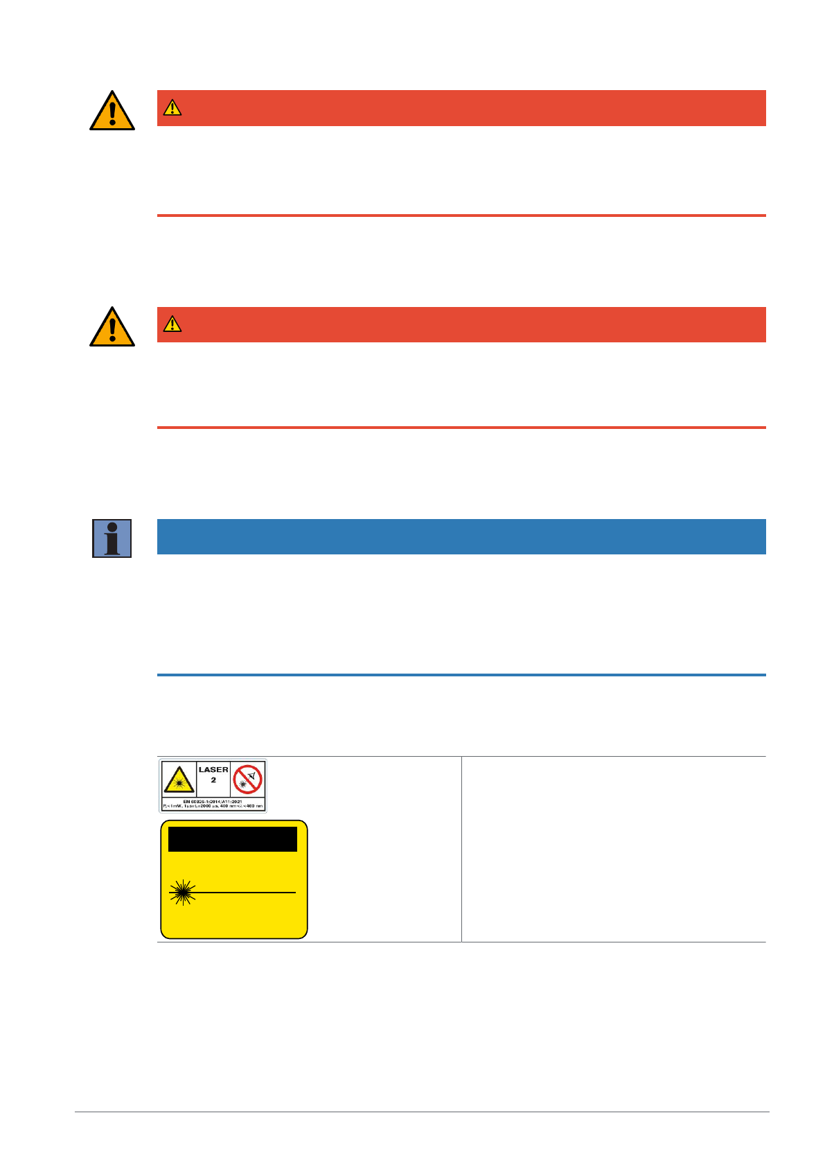
LASER RADIATION
DO NOT STARE INTO BEAM
Complies with 21 CFR
1040.10 and 1040.11 except for conformance
with IEC 60825-1 Ed. 3., as described in Laser
Notice No. 56, dated May 8, 2019
CLASS 2 LASER PRODUCT
CAUTION
Laser Class 2 (EN60825-1)
Applicable standards and safety regulations must
be observed. The accompanying laser warnings
must be attached. Do not look into the laser beam.
Page 8
2 ‒ For Your Safety | P3PC341 ‒ Laser Distance Sensor Triangulation 8
2.7 Approvals and Protection Class
IND. CONT. EQ
72HL / E189727
For use in class 2 circuits
NOTICE
This equipment has been tested and found to comply with the limits for a Class A digital device, pursuant
to part 15 of the FCC Rules. These limits are designed to provide reasonable protection against harmful
interference when the equipment is operated in a commercial environment. This equipment generates,
uses, and can radiate radio frequency energy and, if not installed and used in accordance with the instruc-
tion manual, may cause harmful interference to radio communications. Operation of this equipment in a
residential area is likely to cause harmful interference in which case the user will be required to correct
the interference at his own expense.
This device complies with part 15 of the FCC Rules.
Operation is subject to the following two conditions:
(1) This device may not cause harmful interference, and
(2) this device must accept any interference received, including interference that may cause undesired op-
eration.
FCC Caution: Any changes or modifications not expressly approved by the party responsible
for compliance could void the user’s authority to operate this equipment.
Page 9
3 ‒ Technical Data | P3PC341 ‒ Laser Distance Sensor Triangulation 9
3 Technical Data
3.1 General Data
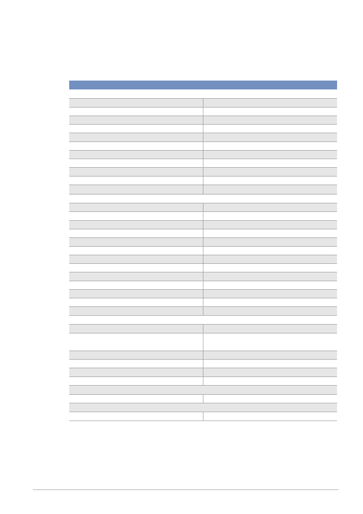
Technical Data
Optical Data
Working Range 60 ... 660 mm
Measuring Range 60 ... 660 mm
Reproducibility maximum 250 µm
Reproducibility: 1Sigma 25 µm
Linearity Deviation 900 µm
Light Source Laser (blue)
Wavelength 405 nm
Service Life (T = +25 °C) 100000 h
Laser Class (EN 60825-1) 2
Max. Ambient Light 5000 Lux
Light Spot Diameter
See section Light Spot Diameter [}10]
Electrical Data
Supply Voltage 18 ... 30 V DC
Current Consumption (Ub = 24 V) < 70 mA
Measuring Rate 2500 /s
Response Time < 0.5 ms
Temperature Drift < 50 µm/K
Temperature Range 0 ... 60 °C
Analog Output 4...20 mA
Short Circuit and Overload Protection yes
Reverse Polarity Protection yes
Interface IO-Link V1.1
Baud Rate COM3
Protection Class III
FDA Accession Number 2310698-000
Mechanical Data
Setting Method (OLED)/Bluetooth menu
Housing Material Aluminum, anodised
Plastic, ABS
Optic Cover Plastic, PMMA
Degree of Protection IP67
Connection M12 × 1; 4/5-pin
Contains FCC ID: 2A3OLDC1392 x
Output Functions
Output Analog Output
Technical Safety Data
MTTFd (EN ISO 13849-1) 398.5 a
Page 10
3 ‒ Technical Data | P3PC341 ‒ Laser Distance Sensor Triangulation 10
NOTICE
The information on accuracy (linearity deviation, reproducibility and temperature drift) refers to the mea-
sured values transmitted via IO-Link.
If an analog output is used, its deviation must be taken into account when considering accuracy. The max-
imum deviation here is:
Analog output 0…10V: +/–15mV at >5kOhm load
Analog output 4…20 mA: +/–25μA at 0…500ohm load
3.1.1 Light Spot Diameter
Working Distance 60 mm 360 mm 660 mm
Light Spot Diameter 1,5 mm 1 mm 0,5 mm
3.2 Warm-Up Phase
The warm-up phase typically lasts 5 minutes. After this time, the sensor delivers the specified values of the
linearity deviation.
NOTICE
Specifications correspond to measured value without load. For all variants, the specification may differ due
to the load on the output.
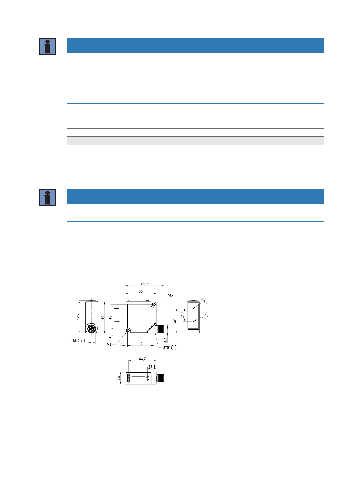
3.3 Housing Dimensions
① = emitter diode
② = receiver diode
M4 screw = 1Nm
M5 screw = 2 Nm
Dimensions in mm (1 mm = 0.03937 inch)
Page 11
3 ‒ Technical Data | P3PC341 ‒ Laser Distance Sensor Triangulation 11
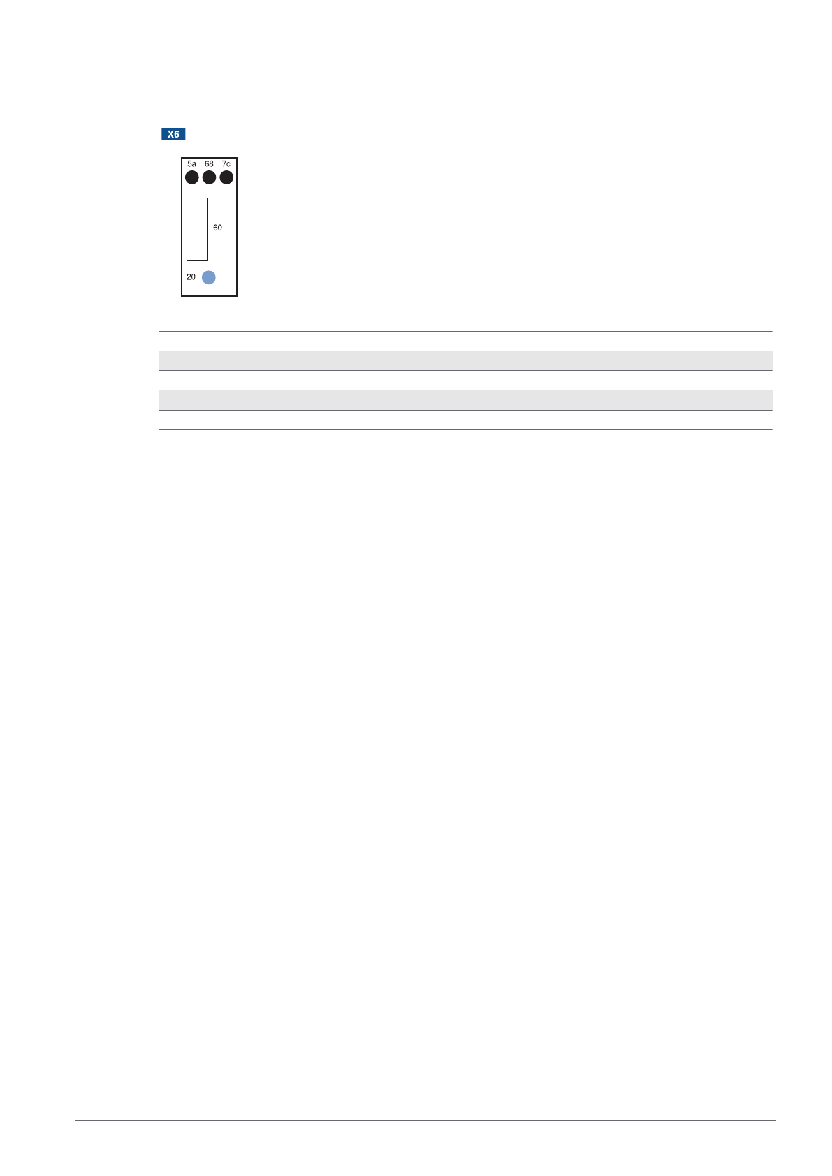
3.4 Control Panel
5a = switching status display, A1
7c = analog output O display
20 = enter key
60 = display
68 = power LED
3.5 Complementary Products
wenglor offers you the right connection and mounting technology as well as other accessories for your
product. You can find this at www.wenglor.com on the product details page at the bottom.
3.6 Scope of delivery
• Sensor
• Safety precaution
Page 12

4 ‒ Transport and Storage | P3PC341 ‒ Laser Distance Sensor Triangulation 12
4 Transport and Storage
4.1 Transport
Upon receipt of shipment, the goods must be inspected for damage in transit. In the case of damage,
conditionally accept the package and notify the manufacturer of the damage. Then return the device, mak-
ing reference to damage in transit.
4.2 Storage
The following points must be taken into consideration with regard to storage:
• Do not store the product outdoors.
• Store the product in a dry, dust-free place.
• Protect the product against mechanical impacts.
• Protect the product against exposure to direct sunlight.
NOTICE
Risk of property damage in case of improper storage!
The product may be damaged.
à Storage instructions must be complied with.
Page 13
5 ‒ Installation and Electrical Connection | P3PC341 ‒ Laser Distance Sensor Triangulation 13
5 Installation and Electrical Connection
5.1 Installation
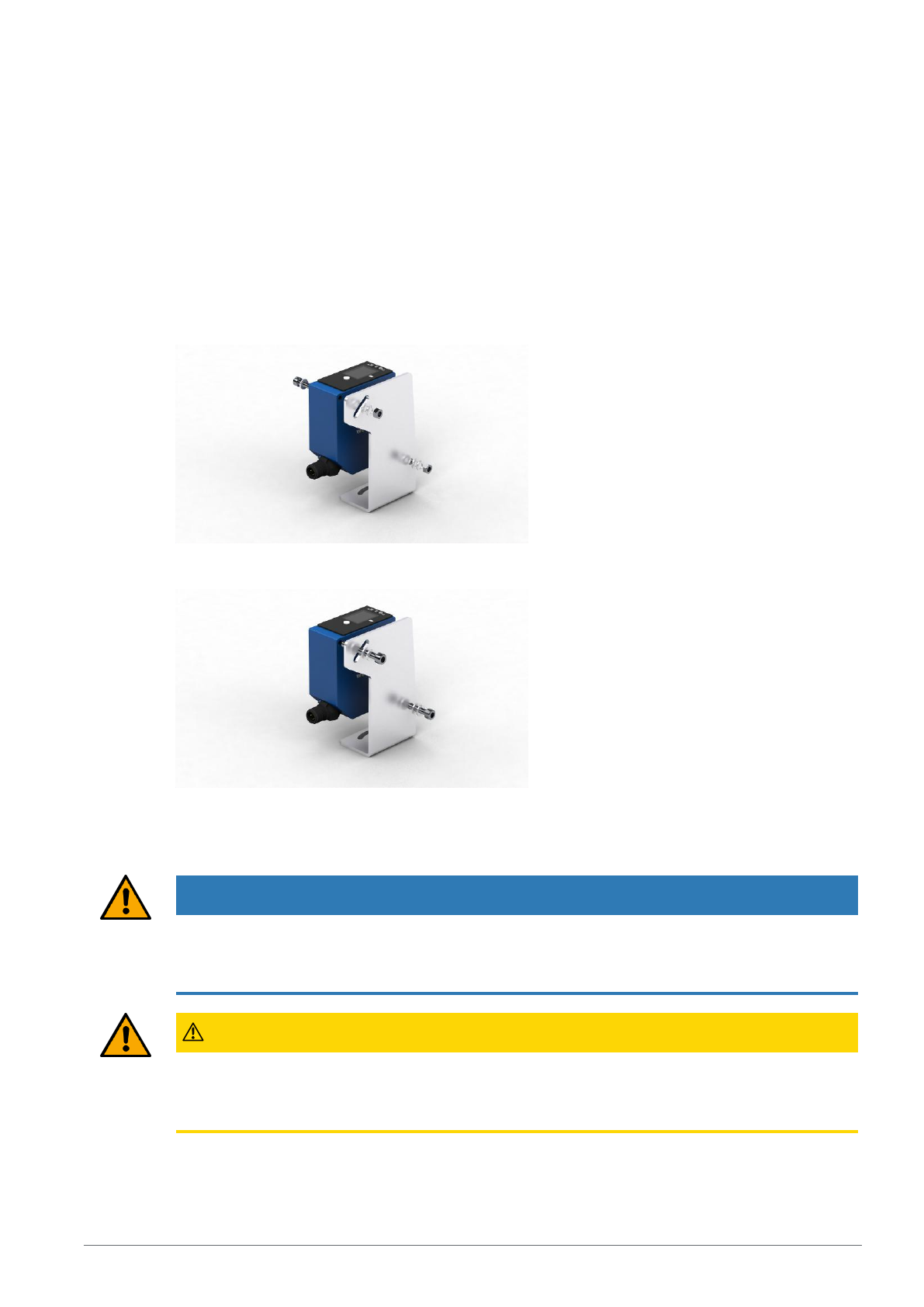
• Protect the product from contamination during installation.
• Relevant electrical and mechanical regulations, standards, and safety rules must be observed.
• Protect the product from mechanical impact.
• Ensure that the sensor is mechanically secure.
• Torque values must be observed (see section Technical Data [}9]).
• Mount the sensor using M4 screws through the mounting hole.
• Alternatively, the sensors can also be mounted with M5 screws using the thread integrated in the
housing.
• Do not exceed the maximum tightening torque:
– When using M4 screws: 1 Nm
– When using M5 screws: 2 Nm
NOTICE
Risk of property damage in case of improper installation!
The product may be damaged!
à Comply with installation instructions.
CAUTION
Risk of personal injury or property damage during installation!
Personal injury and damage to the product may occur.
à Ensure a safe installation environment.
Page 14
5 ‒ Installation and Electrical Connection | P3PC341 ‒ Laser Distance Sensor Triangulation 14
5.2 Adjustment
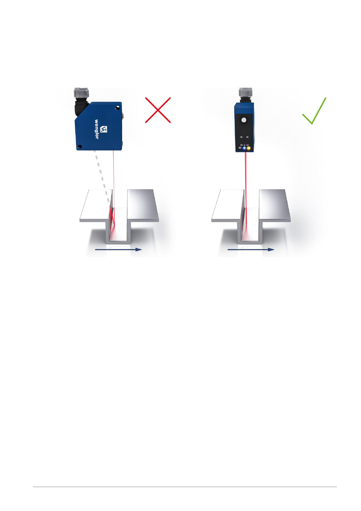
When adjusting sensors, note the following instructions so that the most stable object detection/measure-
ment can be achieved:
Steps/Edges/Depressions
If measuring directly next to steps/edges/depressions, make sure that the receiving beam is not covered
by the step/edge. The same applies when measuring the depth of gaps and holes.
With holes, blind holes and edges in the surface of moving parts, the sensor must be positioned so that
the edge does not obscure the laser dot.
Page 15
5 ‒ Installation and Electrical Connection | P3PC341 ‒ Laser Distance Sensor Triangulation 15
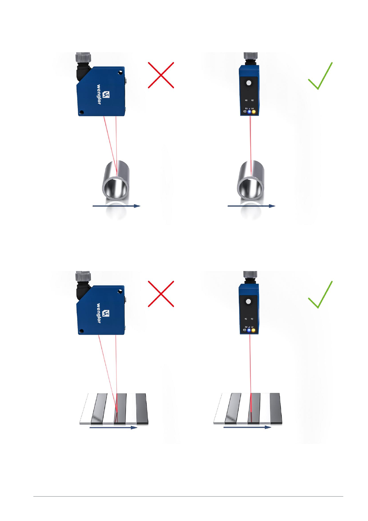
Round, Glossy surfaces
With round, glossy surfaces, the sensor should be positioned on an axis with the round object in order to
avoid reflection.
Measuring Objects with Evenly Positioned, Colored Edges
When oriented correctly, the influence on measuring accuracy is minimal. When oriented incorrectly, the
different reflectivity of the various colors will result in deviations.
Page 16
5 ‒ Installation and Electrical Connection | P3PC341 ‒ Laser Distance Sensor Triangulation 16
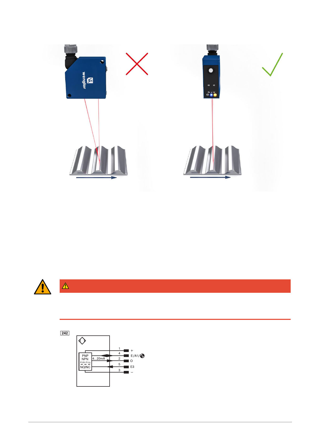
Moving Measuring Objects
When measuring a moving object, the object must be able to move transversely to the sensor. This pre-
vents shadows and direct reflection to the receiver.
5.3 Electrical Connection
• Wire the sensor in accordance with the connection diagram.
• Switch on the supply voltage (see section Technical Data [}9])
• If using IO-Link, connect the sensor to 18…30 V DC.
• If not using IO-Link, connect the sensor to 10…30 V DC.
• The blue supply voltage indicator lights up.
• Adjust the sensor so that the light spot strikes the object to be detected/measured.
DANGER
Risk of personal injury or property damage due to electric current.
Voltage-conducting parts may cause personal injury or damage to equipment.
à The electric device may be connected by appropriately qualified personnel only.
Page 17
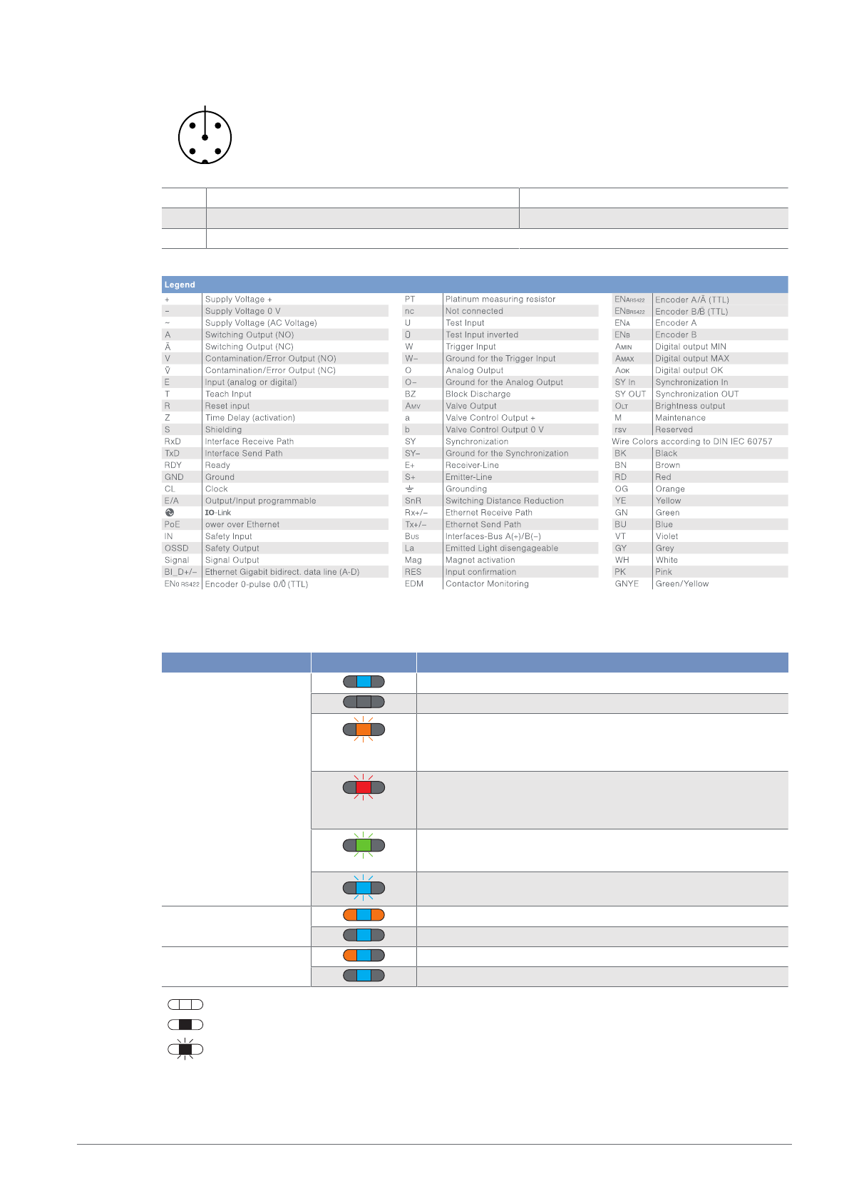
5 ‒ Installation and Electrical Connection | P3PC341 ‒ Laser Distance Sensor Triangulation 17
1 2
34
5
1 Brown 2 White
3 Blue 4 Black
5 Gray
5.4 Diagnosis
display Status Meaning
Power LED
P
sensor ready
No voltage supply available
Warning
The LEDs for switching status indicator A1, A2, and analog
display O remain in operation
Error
The LEDs for switching status indicator A1, A2, and analog
display O are not functioning
Localization
Localization function active
Sensor ready for Bluetooth connection
Switching status indica-
tor A1, A2
Switching outputs active
Switching outputs not active
Analog indicator O Object within set measuring range
Object outside set measuring range
= not lit
= permanently lit
= flashing
Page 18
5 ‒ Installation and Electrical Connection | P3PC341 ‒ Laser Distance Sensor Triangulation 18
5.5 Troubleshooting
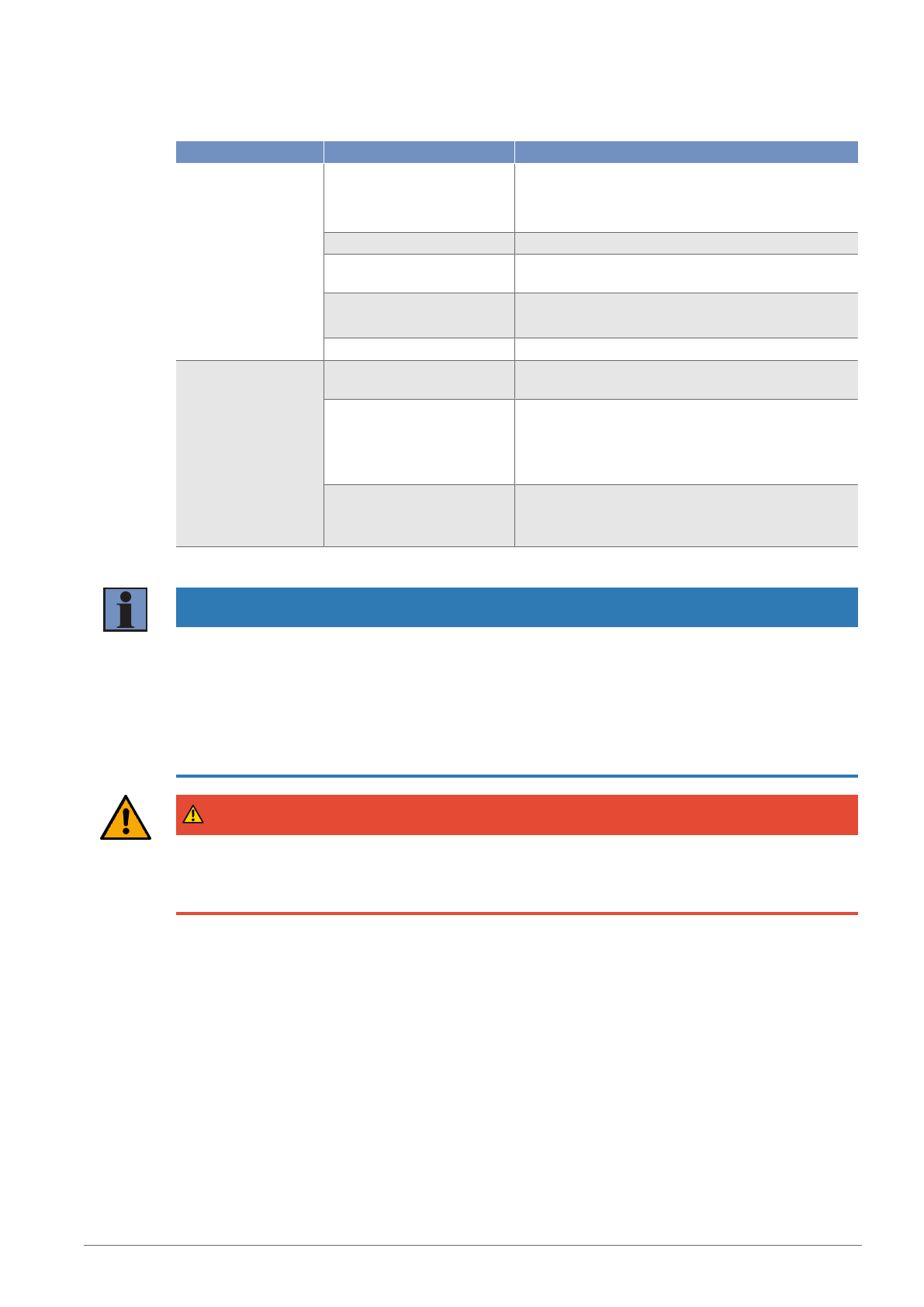
Error Possible cause Remedy
Warning Signal warning • Reduce distance between sensor and object
• Adjust angle between sensor and object
• Remove contamination
Undervoltage • Increase voltage supply to at least 18 V DC
ambient light • Adjust sensor alignment to interfering light
source
Temperature too high • Mount mounting bracket as cooling plate
• Reduce load at the outputs
Temperature too low • Increase ambient temperature
Error Short circuit • Check the electrical wiring and eliminate the
short circuit
Temperature error • Disconnect the sensor from the supply voltage
and allow it to cool
• Mount the mounting bracket as a heat sink
• Reduce load on outputs
Device error • Disconnect the sensor from the supply voltage
and restart it
• Replace the sensor
INFORMATION
Behavior in case of error:
1. Shut down the machine.
2. Analyze and rectify the cause of the error using the diagnostic information.
3. If the error cannot be rectified, contact wenglor support.
4. Do not operate the machine if the error behavior is unclear.
5. The machine must be taken out of service if the error cannot be clearly identified or reliably rectified.
DANGER
Risk of personal injury or property damage if not observed!
The safety function of the system is disabled. Damage to personnel and equipment.
à Behavior in case of error as specified.
Page 19
6 ‒ Settings | P3PC341 ‒ Laser Distance Sensor Triangulation 19
6 Settings
The sensor can be adjusted via teach-in, IO-Link, wTeach2 and weCon. The different setting options are
outlined below.
6.1 Configuration with Push of Button / Teach-In
This section describes the settings that can be configured directly on the sensor using the button.
The settings can also be configured directly using the Enter key and without accessing the menu.
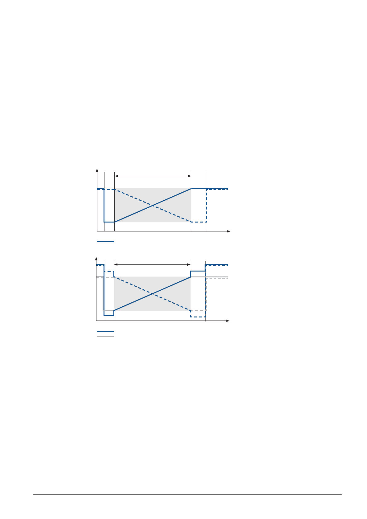
Analog Output
Analog Output Function
The sensor reads out its measured value as a linear proportional current or voltage value. The characteris-
tic curve can be set within the entire measuring range.
9
9
Voltage
Measuring range
No signal
Too close
Too far
No signal
Substitute value active
Distance
P$
P$
P$
P$
P$
Current
Measuring range
No signal
Too close
Too far
No signal
Substitute value active
Distance
Substitute value inactive
Substitute Values (Current Output Only)
By means of substitute values, the sensor is able to provide more precise diagnosis as to whether the
analog signal corresponds to a valid measured value within the measuring range.
No signal: 21 mA
Rising Characteristic Curve
Object outside near measuring range: 3.5 mA
Object outside far measuring range: 20.5 mA
Falling Characteristic Curve
Object outside near measuring range: 20.5 mA
Object outside far measuring range: 3.5 mA
The Substitute Values function can be deactivated via the menu, Bluetooth, or IO-Link.
Teach-In
Page 20
6 ‒ Settings | P3PC341 ‒ Laser Distance Sensor Triangulation 20
The teach-In function can be used to scale the analog output and assign the min./max. values to mea-
sured distances. By default, 4 mA/0 V corresponds to the minimum measuring range, and 20 mA/10 V
corresponds to the maximum measuring range.
300,0
Teach-In for 4 mA/0 V
1. Adjust the sensor so that the light spot strikes the object to be measured.
2. Press and hold the Teach-in key or the Enter key for 2 seconds until O starts to
flash slowly.
3. Release the Teach-in key or the Enter key.
4. The distance is taught in, and LED O flashes briefly twice in order to confirm suc-
cessful teach-in.
1000,0
Teach-In for 20 mA/10 V
1. Adjust the sensor so that the light spot strikes the object to be measured.
2. Press and hold the Teach-in key or the Enter key for 5 seconds until LED O starts to
flash rapidly.
3. Release the Teach-in key or the Enter key.
4. The distance is taught in, and LED O flashes briefly twice in order to confirm suc-
cessful teach-in.
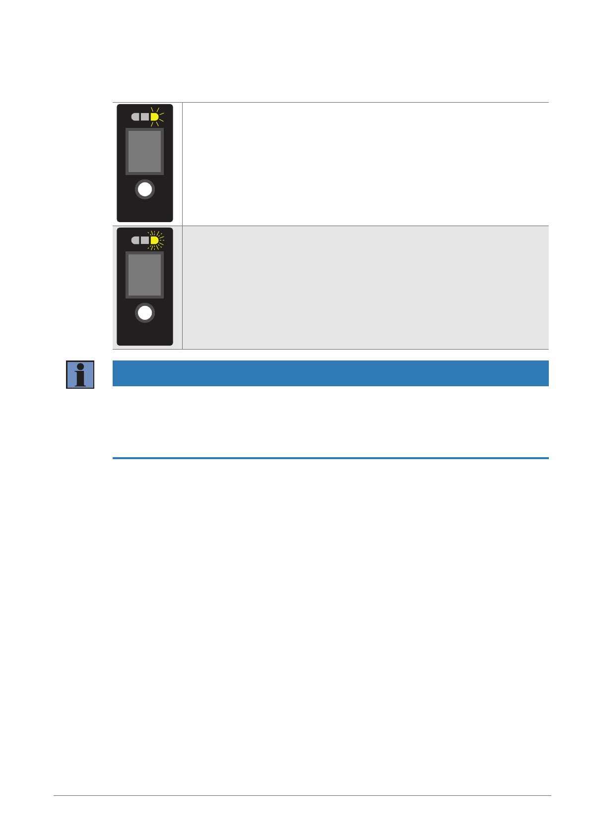
INFORMATION
Depending on whether the smaller distance value is assigned to 4 mA/0 V or 20 mA/10 V, either a rising
or a falling analog characteristic curve results. If teach-in is conducted without an object or if an object is
too far from the sensor, the analog value is set to the maximum value of 20 mA/10 V, and the Power LED
lights up yellow. If an object that is too close is taught in, the analog value is set to the minimum value of
4 mA/0 V, and the Power LED also lights up yellow. If there is an error during teach-in preventing it from
being carried out, this is indicated by a red LED.
Page 21
7 ‒ Settings via menu | P3PC341 ‒ Laser Distance Sensor Triangulation 21
7 Settings via menu
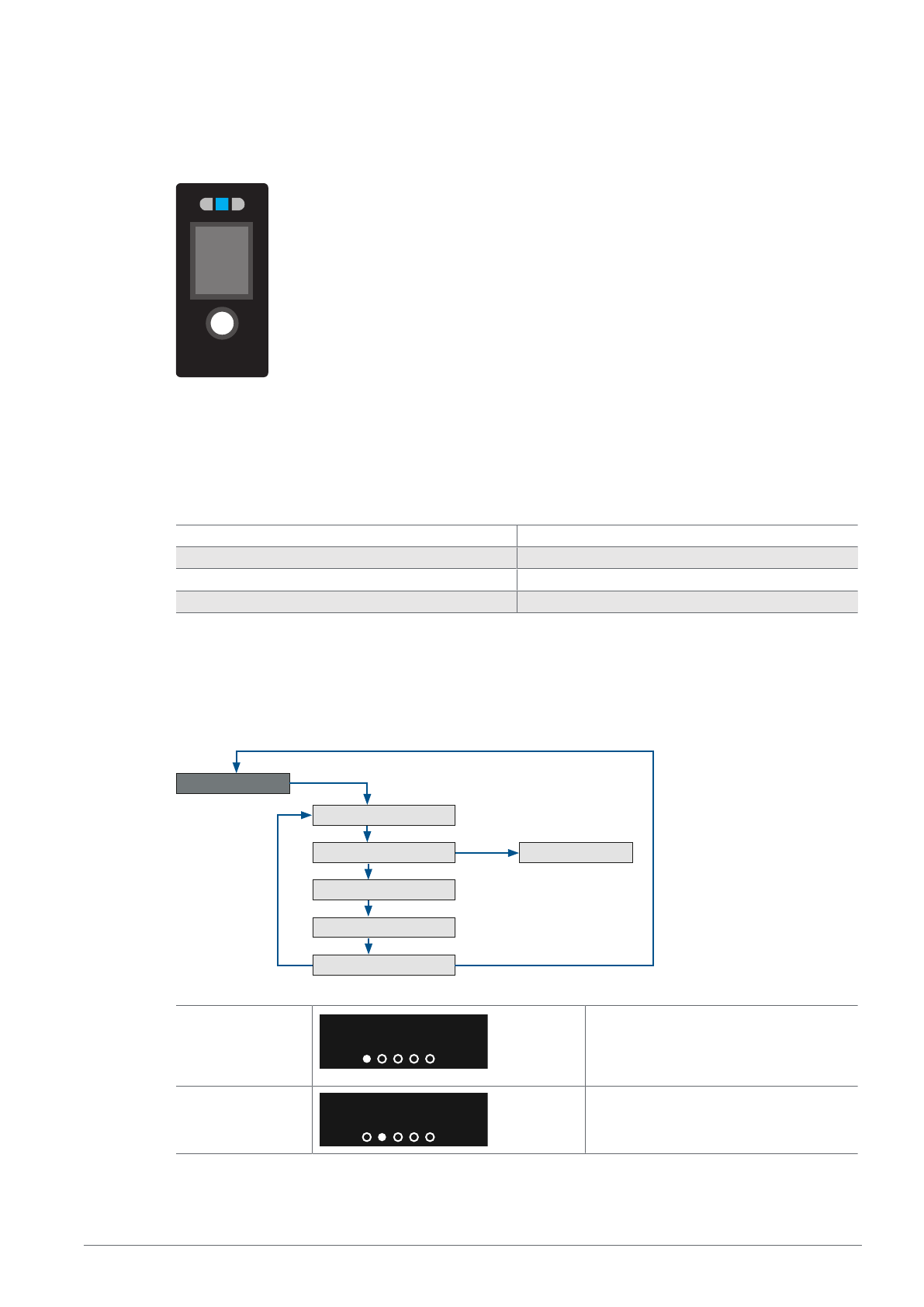
This section describes the settings that can be configured via the integrated OLED display. The menu is
controlled by pressing the Enter button.
The currently measured distance is shown in display mode.
Menu control
Press the Enter button to navigate through the menu and make settings.
Short press in display mode Jump to the menu
Short keystroke Next menu item
Press button for 2 sec. Selection
Press button for 5 sec. Exit the menu, display mode
Menu structure
The menu is divided into 2 areas. Various sensor status messages are displayed in the Info menu. The
Info menu is also used to open the main menu where the settings can be made.
Info menu
'LVSOD\PRGH
/LYH9DOXH
0DLQPHQX
:DUQLQJV(UURUV
%OXHWRRWK6LJQDO4XDOLW\
5XQ
6KRUW
6KRUW
6KRUW
6KRUW
6KRUW
VHF
VHF
6KRUW
Live value
PP
This display is shown after jumping to
the Info menu. The currently measured
distance is displayed in combination
with the measured value unit.
Main menu
0DLQ0HQX
Jump to the main menu to make set-
tings
Page 22
7 ‒ Settings via menu | P3PC341 ‒ Laser Distance Sensor Triangulation 22
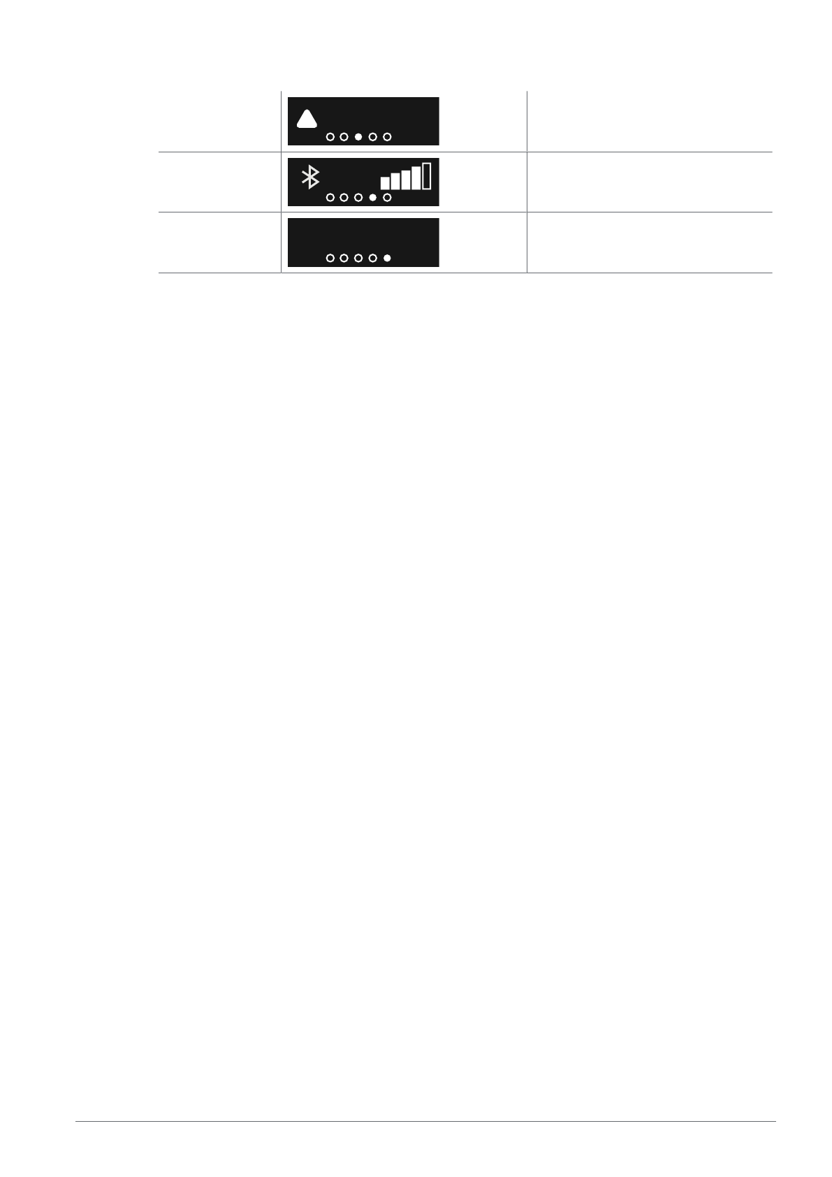
Warnings/Errors
8QGHUYROWDJH
Warnings or errors are displayed in this
view
Bluetooth signal
quality
The Bluetooth signal quality is displayed
in this view.
Display mode
5XQ
Jump back to the display mode
Main menu
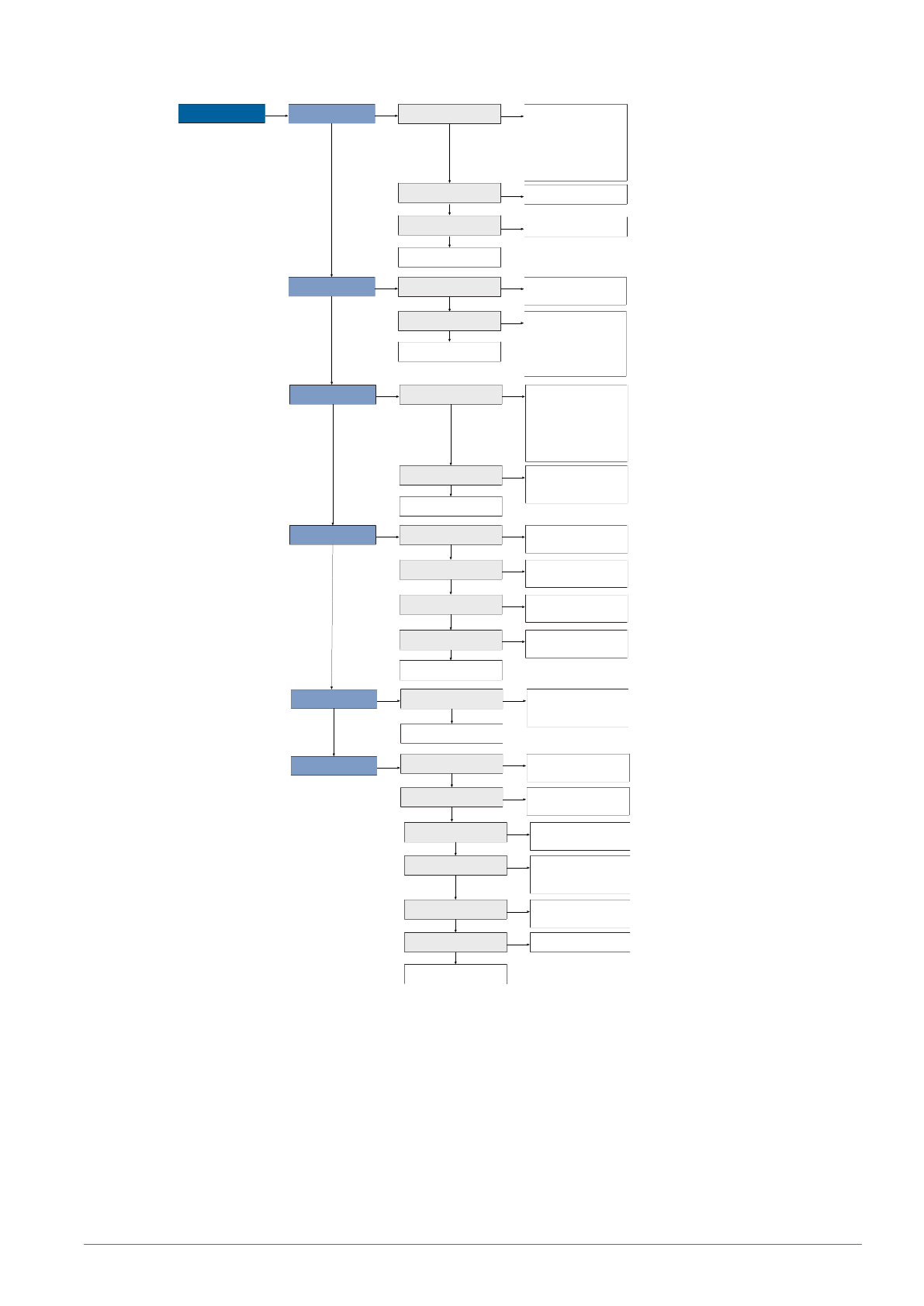
The respective functions are described in the section Parameters [}41].
Page 23
7 ‒ Settings via menu | P3PC341 ‒ Laser Distance Sensor Triangulation 23
Main menu
Teach-in
2 sec.2 sec.
O Analog
- Teach 0 V - Teach 4
mA - Teach 10 V -
Teach 20 mA - Teach
5 V - Teach 12 mA
2 sec.
SSC1 Switch
Short
Short
Teach mode
2 sec.
Back
Short
2 sec.
Teach SSC1
Reference
2 sec.
Referencing
Short
O Analog
- Distance -
Tolerance
2 sec.
Short
SSC1 Switch
- Foreground -
Background -
Window - Jump -
Intensity
2 sec.
Back
Short
Short
I/O A1
Pin function
- SSC output - Error
output - Warning
output - Laser input -
Teach-in input -
Deactivated
2 sec. 2 sec.
E3
Back
Short
- Laser input - Teach-
in input - Deactivated
2 sec.
Short
A1
Switching
- NO contact - NC
contact
2 sec. 2 sec.
Short
Short
E1
Back
Short
Short
E3
2 sec.
- Ub active - 0 V
active
2 sec.
- Ub active - 0 V
active
Short
O Analog
- 0...10 V - 4...20 mA
2 sec.
Short
Bluetooth
- Activated -
Deactivated
2 sec.
Short
Language
2 sec.
Short
Reset Reset
2 sec.
- German - English -
Chinese
Short
Rotate display
- Activated -
Deactivated
2 sec.
Back
Short
A1
Polarity
2 sec. 2 sec.
Short
Back
Measured value Unit
- PNP - NPN - Push-
pull
- Metric - Imperial
2 sec.
Short
Substitute values
- Activated -
Deactivated
2 sec.
Short
Settings
2 sec.
Short
Page 24
8 ‒ Function Description | P3PC341 ‒ Laser Distance Sensor Triangulation 24
8 Function Description
The functions described in the following section can be adjusted via wTeach or IODD per IO-Link, as well
as via the weCon app per Bluetooth, and the basic functions via the Display menu.
8.1 Sensor Functions
Function Possible settings Default
Exposure mode With black or glossy objects, it may be useful to increase the
exposure time. Decreasing the exposure time can be useful if
the sensor is aimed at very bright objects. The longer the ex-
posure time, the lower the speed of the sensor.
Auto
With the Adaptive Autoexposure function, the sensor automati-
cally sets its exposure time or light pulse duration to the object
to be detected up to a maximum value.
Fix
The exposure time is set via the fixed exposure time parame-
ter, i.e., not automatically adjusted by the sensor
Auto
Fixed
exposure time
Used to manually set a fixed exposure time.
1…1,600 μs
1,600 µs
Maximum
exposure time
Maximum exposure time in Auto mode.
1...1,600 μs
1,600 µs
Measured value filter A bigger filter improves the sensor’s reproducibility and
smooths the signal waveform. The higher the filter number, the
longer the sensor’s response time when the measured values
change.
0 = OFF
1…9
3
Offset The Offset function is used to change the momentary mea-
sured value to a specified value. The switching thresholds and
the analog measuring ranges are adapted along with this
value. The offset value is added to the current distance.
0 µm
Offset specification Value to which the current measured value is to be set by a
corresponding offset. The offset is calculated automatically.
60,000…660,000 μm
0 µm
Apply offset specifi-
cation
The current measured value is changed to the offset specified
value
1= apply
0
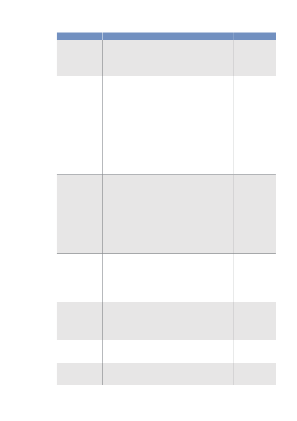
Distance range A distance range in which signals are to be evaluated can be
defined within the working range. Signals outside the set dis-
tance range are ignored and are not included in the signal
evaluation. This means that ranges for which no usable sig-
nals are expected can be completely hidden.
This function can be used to suppress interfering signals, such
as those produced by a glass disk, for instance.
Min. distance: working range
Max. distance: working range
Note!
Setting range
Page 25
8 ‒ Function Description | P3PC341 ‒ Laser Distance Sensor Triangulation 25
Function Possible settings Default
• Objects outside the set distance range are evaluated as
“No signal”.
• If a distance range is set, a blind spot directly behind this
range results. The sensor cannot detect any objects within
the blind spot. The size of the blind spot depends on the
reflectance of the interfering objects in the hidden area.
Sensitivity The sensor has a very high sensitivity and can detect objects,
measuring the distance to them, even when the signal is very
weak. In applications where the object to be detected yields
even weaker signals, e.g., due to large inclinations, it can be
helpful to further increase the sensitivity or to amplify the opti-
cal signal.
The higher the sensitivity, the more susceptible the sensor is
to interference. The speed of the sensor is not reduced by the
setting.
Standard
Corresponds to the default setting
High
Gain by factor 2
Maximum
Gain by factor 4
Standard
Emitted light The sensor’s laser can be switched on or off.
On
Laser on
Off
Laser off
The sensor no longer supplies a measured value.
Note!
• If an input is set as a laser-off input, the emitted light can
also be switched on and off via the input.
• If the laser is switched off, the sensor behavior corre-
sponds to the status “No signal.”
On
Localization The supply voltage indicator of the sensor can be switched to
flashing green. This allows the sensor to be easily located in a
plant.
On
The supply voltage LED flashes green.
Off
LEDs in normal function.
Off
Measured value unit The measured distance can be output in micrometers or mils.
Micrometer
Distance values output in μm.
Mil
Distance values read out in mil.
micrometer
Bluetooth The Bluetooth interface can be switched on/off.
On
Off
On
Bluetooth
Password
Function
The Bluetooth function can be password protected to prevent
unauthorized access.
On
Off
Page 26

8 ‒ Function Description | P3PC341 ‒ Laser Distance Sensor Triangulation 26
Function Possible settings Default
Off
Note!
Only the Bluetooth function is protected. Communication is
possible via IO-Link or the OLED menu at any time.
Bluetooth
Password
Enter a Bluetooth password. To access the device using the
Bluetooth app, enter this password in the app.
Note!
If the password has been forgotten, a new password can be
assigned via IO-Link.
--
8.2 Display Functions
Function Possible settings Default
Language Setting the menu language
German
English
Chinese
English
Rotate display Rotate display 180°
On
Off
Off
8.3 Input/Output Functions (E/A)
8.3.1 Pin Function
The pin function is used to define the function of pins E/A1 and E3, as these can be used for different
functions.
Pin Possible settings Default
E/A1 Switching output
Switching point SSC1 is assigned to the switching output.
Error output
The error output switches if one of the assigned errors occurs;
see table Status messages [}37]
Warning output
The warning output switches if one of the assigned warnings
occurs; see table Status messages [}37].
Laser-off input
See E3 for an explanation
Teach-in input
See E3 for an explanation
Deactivated
The pin is deactivated.
Error output
E3 Laser-off input Laser off
Input
Page 27
8 ‒ Function Description | P3PC341 ‒ Laser Distance Sensor Triangulation 27
Pin Possible settings Default
The sensor’s emitted light is deactivated as long as the input
is activated. The sensor then does not send a measured value
and sets the status to “No signal”.
Teach-In input
Teach-in
The outputs (switching outputs/analog output) can be set by
following the same procedure as with the Teach-in key (see
Configuration with Push of Button / Teach-In [}19]). An acti-
vated input corresponds to a pressed Teach-in key.
Locking
If 18…30 V DC is continuously applied to the teach-in input,
the teach-in key is locked and protected against inadvertent
changes, like the input signal.
Deactivated
The pin is deactivated.
8.4 Output Functions
The output functions are used to set the physical outputs.
Digital Outputs
Function Possible settings Default
Polarity PNP
NPN
Push-pull
PNP
Circuit NO
Light switching (Normally Open)
The output is high when the condition has been satisfied, de-
pending on settings (switching point, warning, error).
NC
Dark switching (normally closed)
The output is low when the condition has been fulfilled de-
pending on the setting (switching point, warning, error).
NO
On-delay 0…10,000 ms 0 ms
Off-delay 0…10,000 ms 0 ms
Analog outputs
Function Possible settings Default
Teach-in Starts the teach-in process.
Teach-in mode Distance
A distance is taught in to the analog limit values, and the dis-
tance is output as a linearly proportional current or voltage
value.
Sensor
4 mA / 0 V
20mA / 10V
20 mA/0 V
4 mA/10 V
Tolerance
Distance
Page 28
8 ‒ Function Description | P3PC341 ‒ Laser Distance Sensor Triangulation 28
Function Possible settings Default
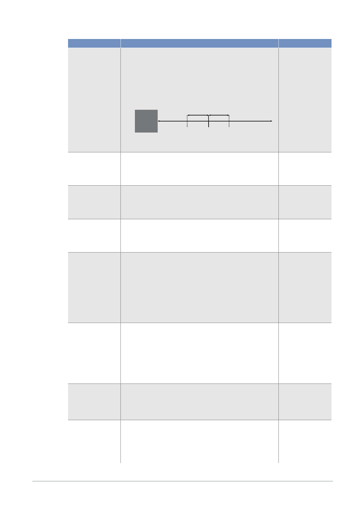
A distance is taught in to the measuring range, serving as the
measurement reference, for 5 V or 12 mA. The tolerance
range is set around this value.
Sensor
12 mA/5 V
Tolerance range
Pos. gradient:
4 mA / 0 V
Neg. gradient:
20mA/0 V
Pos. gradient:
4 mA / 0 V
Neg. gradient:
20mA/0 V
0 V / 4 mA In Distance teach-in mode
In Distance teach-in mode, the 0 V or 4 mA value is assigned
to a distance within the measuring range.
Measuring range
60,000 µm
10 V / 20 mA In Distance teach-in mode
In Distance teach-in mode, the 10V or 20mA value is as-
signed to a distance within the measuring range.
Measuring range
660,000 µm
5 V / 12 mA With teach-in mode Tolerance
In teach-in mode Tolerance, the 5 V or 12 mA value is as-
signed to a distance within the measuring range.
Measuring range
360,000 µm
Tolerance range For teach-in mode Tolerance
The tolerance range is placed symmetrically around the 5 V/
12 mA point and defines the range in which the measurement
takes place.
1,000…660,000 μm
Note!
If the tolerance range extends beyond the limits of the measur-
ing range, the corresponding analog values or substitute val-
ues for outside the measuring range are output from there.
300,000 µm
Tolerance character-
istic
For teach-in mode Tolerance
The characteristic indicates whether the analog value in-
creases or decreases with increasing distance.
Positive slope
The analog value increases with increasing distance
Negative slope
The analog value falls with increasing distance
Positive slope
Analog mode Current output
4…20 mA
Voltage output
0…10 V
4…20 mA
Analog
Replacement values
The substitute values described in the section Settings– Ana-
log output can be activated or deactivated.
Enabled
Sensor outputs substitute values.
Deactivated
Enabled
Page 29
8 ‒ Function Description | P3PC341 ‒ Laser Distance Sensor Triangulation 29
Function Possible settings Default
Sensor does not use substitute values.
Note!
Function can only be used for current output.
8.5 Input Functions
The input functions are used to set the physical inputs.
Function Possible settings Default
Input mode Supply voltage active
Function is triggered as soon as supply voltage is applied to
the input.
Supply voltage inactive
Function is triggered as soon as 0V is applied to the input or
the input is opened.
Supply voltage ac-
tive
8.6 Switching Point Functions (SSC1/SSC2)
The switching point functions are used to set the two switching points, SSC1 and SSC2.
SSC1 and SSC2 initially only available via IO-Link. If I/O1 is configured as a switching output, it is as-
signed to SSC1.
Function Possible settings Default
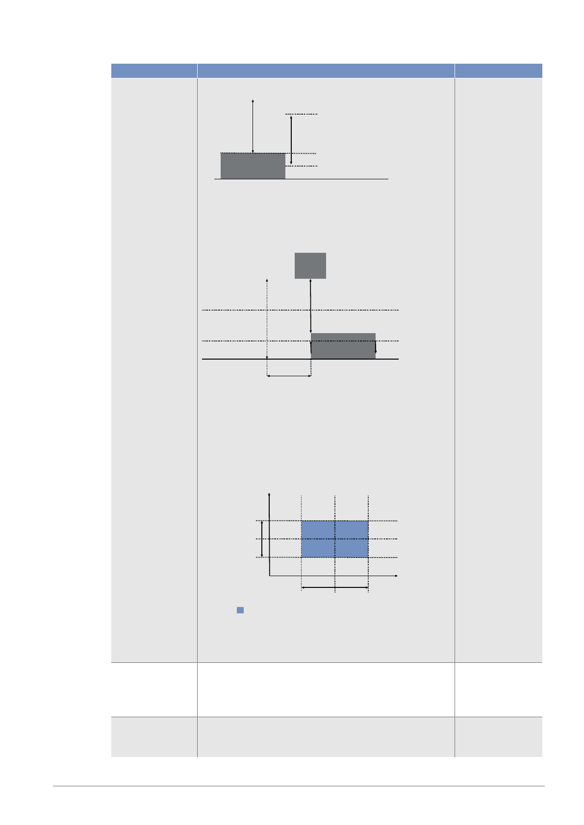
Teach-in Starts the teach-in process.
Teach-in
mode
Foreground Teach-In
Object
Sensor
Teach-in distance
Switching point
Background Teach-In
Object
Sensor
Teach-in distance
Switching point
Window Teach-In
Foreground teach-in
Page 30
8 ‒ Function Description | P3PC341 ‒ Laser Distance Sensor Triangulation 30
Function Possible settings Default
Object
Sensor
Near switching point
Far switching point
Window size
Switching point
Teach-in
distance
Jump Detection
In this mode, there is no switch to an absolute measured
value, but rather to a measured value jump occurring between
2measurements.
Object
Current measured value
Sensor
Positive
Negative
Reference
measured
value
Max. jump height
Min. jump height
Time offset
Distance and Intensity
In this mode, the intensity of the received signal is also evalu-
ated for distance. The sensor is taught in a reference that con-
sists of a switching point for the distance and a switching
point for the intensity. As soon as the sensor detects a devia-
tion in distance or intensity, this is registered via the output.
Intensity
Distance Window
Intensity
Switching
Point
Intensity
Window
Switching Point
Taught-in reference from Distance and Intensity
Note!
The teach-in function is necessary to ensure that the sensor
works properly.
Switching point 60,000…660,000 μm
Note
If a distance range has been set, the switching point can only
be set within the set distance range.
660,000 μm
Hysteresis mode Hysteresis is the difference between the switch-on and switch-
off points.
Auto
Auto
Page 31

8 ‒ Function Description | P3PC341 ‒ Laser Distance Sensor Triangulation 31
Function Possible settings Default
The hysteresis is automatically calculated by the sensor in or-
der to optimally adapt it to the respective situation. After a
teach-in or change of the switching point, the hysteresis is re-
calculated and automatically updated in the hysteresis param-
eter. The information in the data sheet refers to the set switch-
ing point, e.g., switching point at 100 mm, hysteresis accord-
ing to data sheet < 0.5% hysteresis < 0.5 mm
Fixed
The hysteresis is set to a fixed value in the Hysteresis parame-
ter. This is not automatically adjusted during a teach-in or a
change of the switching point. A small hysteresis is recom-
mended for detecting flat objects against a background, while
a larger hysteresis is recommended to ensure stable detection
under changing conditions.
hysteresis Absolute value of the hysteresis in hysteresis mode. Fixed
5 μm…660,000 μm
1,800 μm
Window switching
point close
In teach-in mode window teach-in
Distance from the set window center to the switching point of
the window close to the sensor.
The window can be set so that it extends from the minimum
setting range to the maximum setting range of the sensor. The
minimum and maximum possible settings result from the re-
spective set window center.
30 mm
Window switching
point far
In teach-in mode window teach-in
Distance from the set window center to the switching point of
the window far from the sensor.
The window can be set so that it extends from the minimum
setting range to the maximum setting range of the sensor. The
minimum and maximum possible settings result from the re-
spective window center setting.
30 mm
Jump height min In teach-in mode Jump detection
The minimum jump height defines the jump in the measured
value at which a jump event is to be detected.
In the "Automatic" setting, the sensor calculates the smallest
possible jump independently.
0 = Automatic
8 μm…660,000 μm
Automatic
Maximum jump
height
In teach-in mode, jump detection
The max. jump height defines the maximum jump in the mea-
sured value at which a jump event is to be detected.
In the "No restriction" setting, there is no limit to the max. jump
height. A change from a valid measured value to "No mea-
sured value" is evaluated as a negative jump.
4294967295 = No restriction
8 μm…660,000 μm
no limit
Jump direction In teach-in mode, jump detection
Positive
A jump is detected when the measured value jumps to a
higher value, i.e. the contrast value becomes brighter.
Negative
A jump is detected when the measured value jumps to a lower
value, i.e. the contrast value becomes darker.
Both
Negative
Page 32
8 ‒ Function Description | P3PC341 ‒ Laser Distance Sensor Triangulation 32
Function Possible settings Default
A jump is detected for both positive and negative.
Cycle offset In teach-in mode Jump detection
The cycle offset specifies the time-shifted reference measured
value with which the current measured value is to be com-
pared in order to detect the jump.
1…256 Cycles
50
Jump pulse duration In teach-in mode Jump detection
0 = hold
The output remains active until the next jump in the opposite
jump direction is detected.
A combination with the jump direction "Both" is not permitted
here.
1…10,000 ms
When a jump is detected, the output is activated with the cor-
responding pulse length.
0
Distance Window In teach-in mode Distance + Intensity
Distance from the set switching point (center of the window) to
the boundaries of the window.
The distance window is symmetrical around the switching
point.
5 μm…10,000 μm
1,800 µm
Switching point In-
tensity
In teach-in mode Distance + intensity
Switching point of intensity in digits
1…1,000,000
30,000
Intensity window In teach-in mode, distance + intensity
from the set switching point intensity (center of the window) to
the limits of the window.
The intensity window is symmetrical around the switching
point.
1…50%
4%
8.7 Differential and Thickness Measurement
In this operating mode, two sensors work together to calculate a difference or thickness based on the in-
dividual measurement results.
This eliminates the need for complex programming in the controller, and the system already provides a
calculated value. This value can then be used for a switching function or output via an analog output. Ad-
ditionally, the calculated difference or thickness is output as an absolute value via IO-Link.
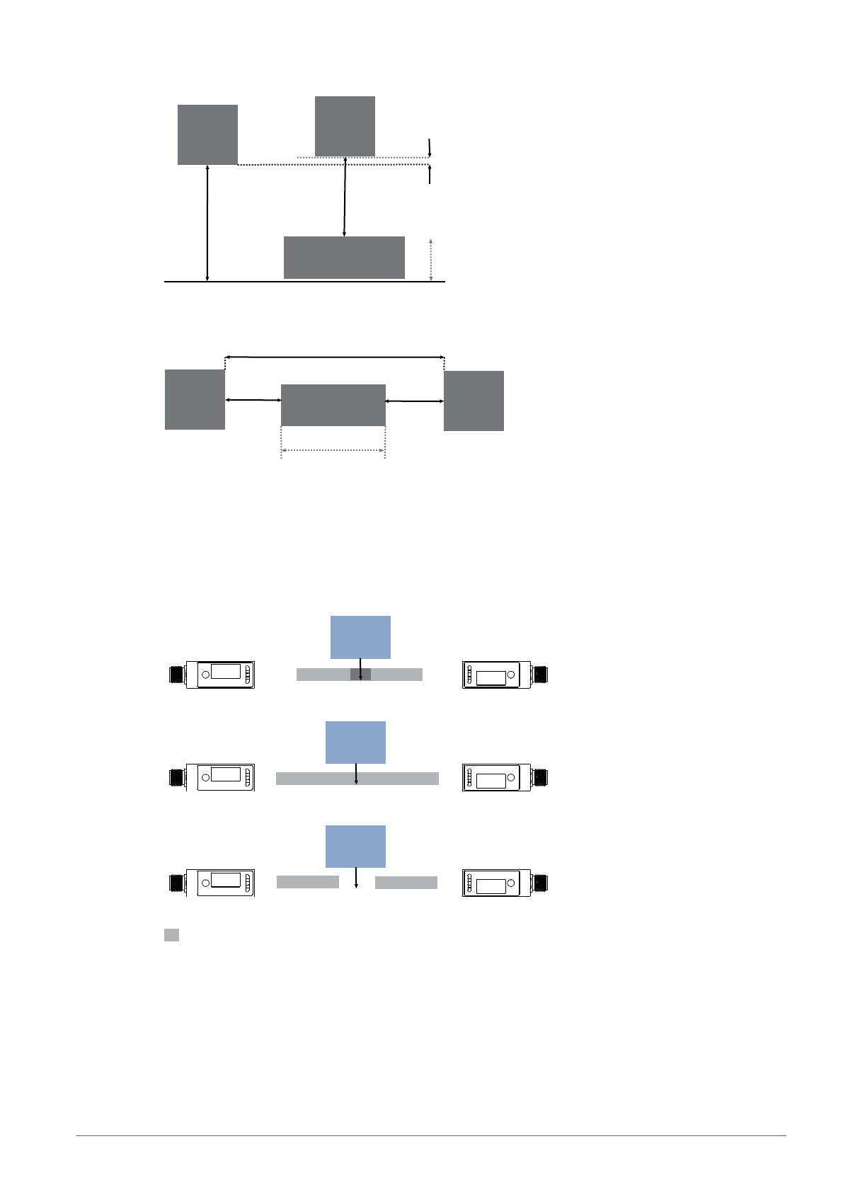
Mechanical Design
differential measurement
Page 33
8 ‒ Function Description | P3PC341 ‒ Laser Distance Sensor Triangulation 33
Sensor
Secondary
Sensor
Main
Reference object
Sensor alignment offset
Reference thickness
thickness measurement
Sensor
Secondary
Sensor
Main
Ref. object
Sensor distance
Reference thickness
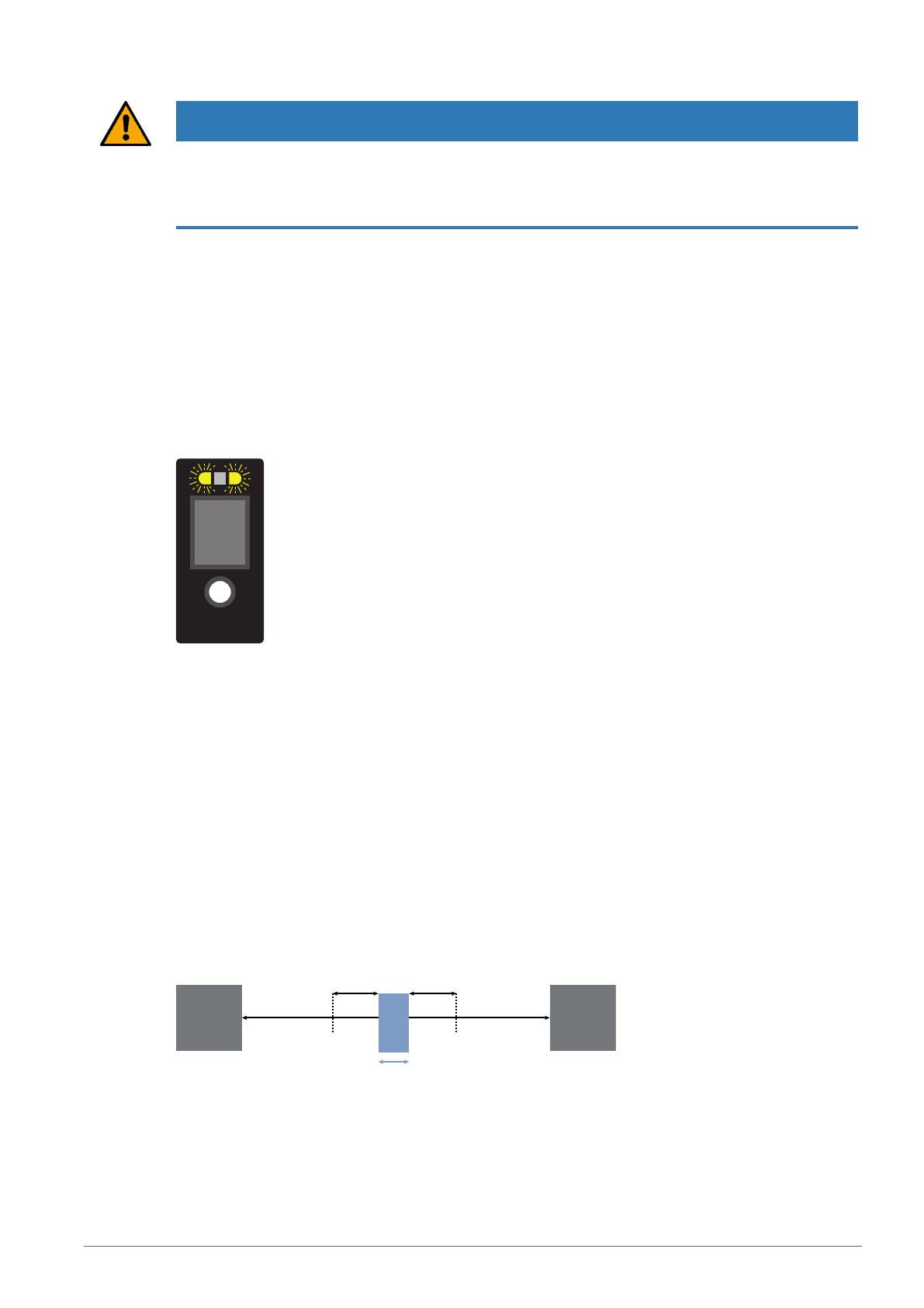
It is recommended to arrange the sensors so that no area between the sensors remains uncovered by
their measuring range (Figs. 1 and 2). If this is the case, the object to be measured must be wider than
the uncovered area (Fig. 3).
The sensors must be aligned so that the transmitted beams strike the front window of the opposite sen-
sor. Care must be taken to ensure that they do not strike the emitter or receiver directly.
Object
Object
Object
Fig. 1
Fig. 2
Fig. 3
Working range
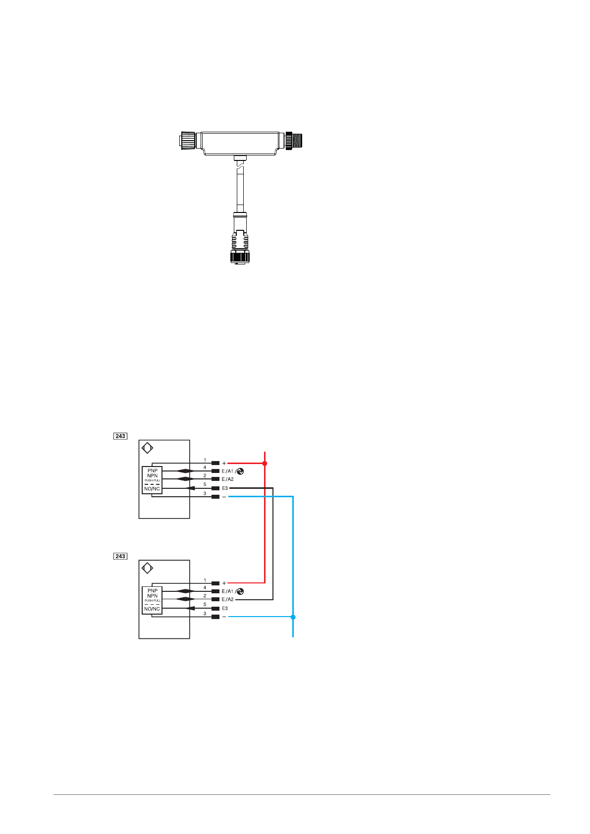
Wiring
With adapter
Page 34
8 ‒ Function Description | P3PC341 ‒ Laser Distance Sensor Triangulation 34
The ZC4G004 adapter can be used for easy wiring. In this case, the sensors must simply be connected
as shown. The sensors are automatically parameterized for the appropriate operating modes as soon as
they are connected. In this case, the main sensor is set to "thickness measurement" mode. If a differential
measurement is to be performed, the mode of operation must be adjusted accordingly.
Sensor
Main
Controller
Sensor
Secondary
The adapter’s connections can be extended using connection cables. Note that 5-pin connection cables
must be used for the sensors. When connecting an IO-Link master on the control side, a 4-pin connection
cable must be used.
Direct Wiring
As an alternative to using the adapter, wiring can also be done directly via terminal blocks or within a con-
troller. To do this, connect the sensors according to the following wiring diagram. The operating modes
must be set manually in each sensor.
0DLQ
8E
*1'6HFRQGDU\
The example shows the use of 2 digital sensors. In this case, switching points can be set via pins 2 and 4
on the main sensor based on the calculated difference or thickness. Two analog sensors or a combina-
tion of digital and analog sensors can also be used. In that case, the calculated thickness can then be
tapped as an analog signal at the analog output of the main sensor.
Page 35
8 ‒ Function Description | P3PC341 ‒ Laser Distance Sensor Triangulation 35
NOTICE
Sensors with different measuring ranges can also be combined. In this case, the respective working
ranges must be taken into account during installation.
A combination of versions with red and blue lasers is also possible. This combination is recommended if,
due to the installation situation, the sensors interfere with each other when no object is present.
Calibration
To perform thickness or differential measurements, the system must be referenced after mechanical as-
sembly and wiring.
During this process, the sensors automatically calibrate their distances from one another so that the mea-
surement results can be calculated according to the setup. Calibration can be performed via the teach-in
key or Enter button, via the OLED menu, Bluetooth, or via IO-Link.
The reference object must be positioned in the measuring system according to the mechanical setup. For
referencing via the teach-in key, hold it down for 10 seconds until the two LEDs begin to flash. Then re-
lease the key. The LEDs will flash twice briefly to confirm. The sensors are now referenced.
540,0
Outputs
If a sensor is in the Main Thickness/Difference mode of operation, the calculated thickness or difference is
used for output at the outputs.
SSC1/SSC2
All settings can be configured identically to standalone operation. However, the switching points do not
correspond to a distance, but rather to the thickness/difference. The switching points are set via separate
parameters. All other settings are configured using the general parameters of SSC1/SSC2.
Analog output
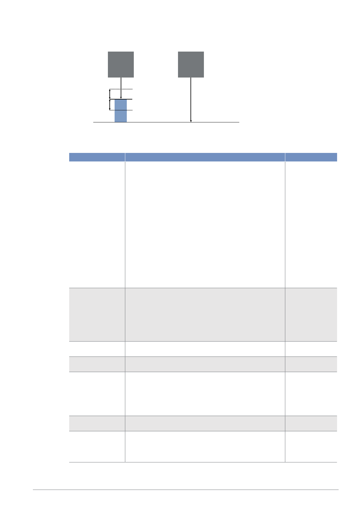
In this operating mode, the analog output functions exclusively in tolerance mode. The reference value
corresponds to 12 mA or 5 V at the analog output. The tolerance range and characteristic can be set via
separate parameters.
Sensor Sensor
Tolerance range Tolerance range
12 mA/5 V
4 mA/0 V 20 mA/10 V
Thickness measurement
Page 36
8 ‒ Function Description | P3PC341 ‒ Laser Distance Sensor Triangulation 36
Sensor Sensor
Tolerance Range
Tolerance range
12 mA/5 V
4 mA/0 V
20 mA/10 V
Differential measurement
Settings
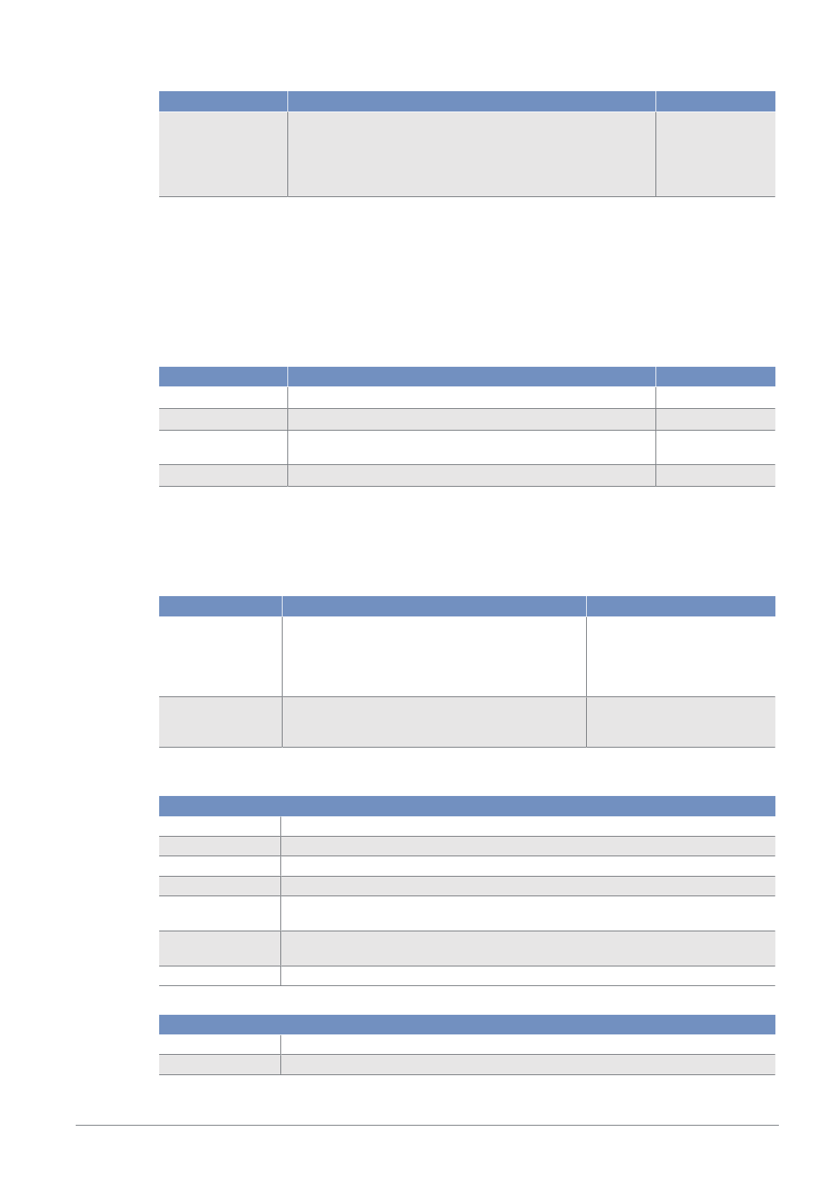
Function Possible settings Default
Mode of operation Stand Alone
The device functions as a stand-alone device.
Secondary
The sensor provides measurement data for a main device.
Main Thickness
The sensor performs a thickness measurement using the con-
nected secondary.
Main Difference
The sensor performs a differential measurement using the
connected secondary.
Automatic
This setting is used to enable automatic detection of the
ZC4G004 adapter, when in use, and to preset the operating
mode according to the connection. The main sensor is set to
Thickness mode.
Automatic
Referencing Start of the referencing process
To do so, the reference object must be placed in the measur-
ing system, depending on the mechanical layout, and refer-
encing started.
With an analog sensor, 5V / 12mA is applied automatically to
the analog output after referencing. Changes, in comparison
to the reference thickness, are now output accordingly.
Sensor alignment off-
set (difference)
When referencing, the offset is calculated using the specified
reference thickness.
0 μm
Sensor distance
(thickness)
When referencing, the sensor distance is calculated using the
specified reference thickness.
1,320,000 µm
Reference thickness The reference thickness corresponds to the true thickness of
the reference object. This thickness is used by the sensor to
calculate the absolute value that is output by the main sensor
via IO-Link.
For analog main sensors, the reference thickness is assigned
the analog value 12 mA or 5 V.
0 μm
Switching point Switching point in relation to a thickness or difference used for
the function of SSC1 and SSC2.
Tolerance range The tolerance range is arranged symmetrically around the 12
mA/5 V value and defines the range by changing the analog
value linearly with the measured value.
600,000 μm
1,000…600,000
μm
Page 37
8 ‒ Function Description | P3PC341 ‒ Laser Distance Sensor Triangulation 37
Function Possible settings Default
Tolerance character-
istic
Positive slope
The analog value increases as the thickness increases.
Negative slope
The analog value falls as the distance increases.
Positive slope
8.8 Condition Monitoring Functions
8.8.1 Status Message Function
The sensor provides various status messages. Due to the process data structure, four status messages
can be transmitted as individual process data.
These parameters can be used to set the status messages that are transmitted via the process data.
Function Possible settings Default
Message 1
See table “Status Messages” [}37]
Warning signal
Message 2
See table “Status Messages” [}37]
Ambient light
Message 3
See table “Status Messages” [}37]
Temperature too
high
Message 4
See table “Status Messages” [}37]
Short circuit
8.8.2 Warning/Error Output Function
The status messages used to trigger the collective message can be defined for the warning output and
the error output respectively. The status messages are OR-linked so that the output is activated when one
of the defined status messages is activated.
Function Possible settings Default
Warning output See table “Status Messages” Signal warning, optics dirty, am-
bient light, temperature too
high, temperature too low, un-
dervoltage, interference in the
working range
Error output See table “Status Messages” Object too close, object too far,
no signal, device error, over-
temperature, short circuit
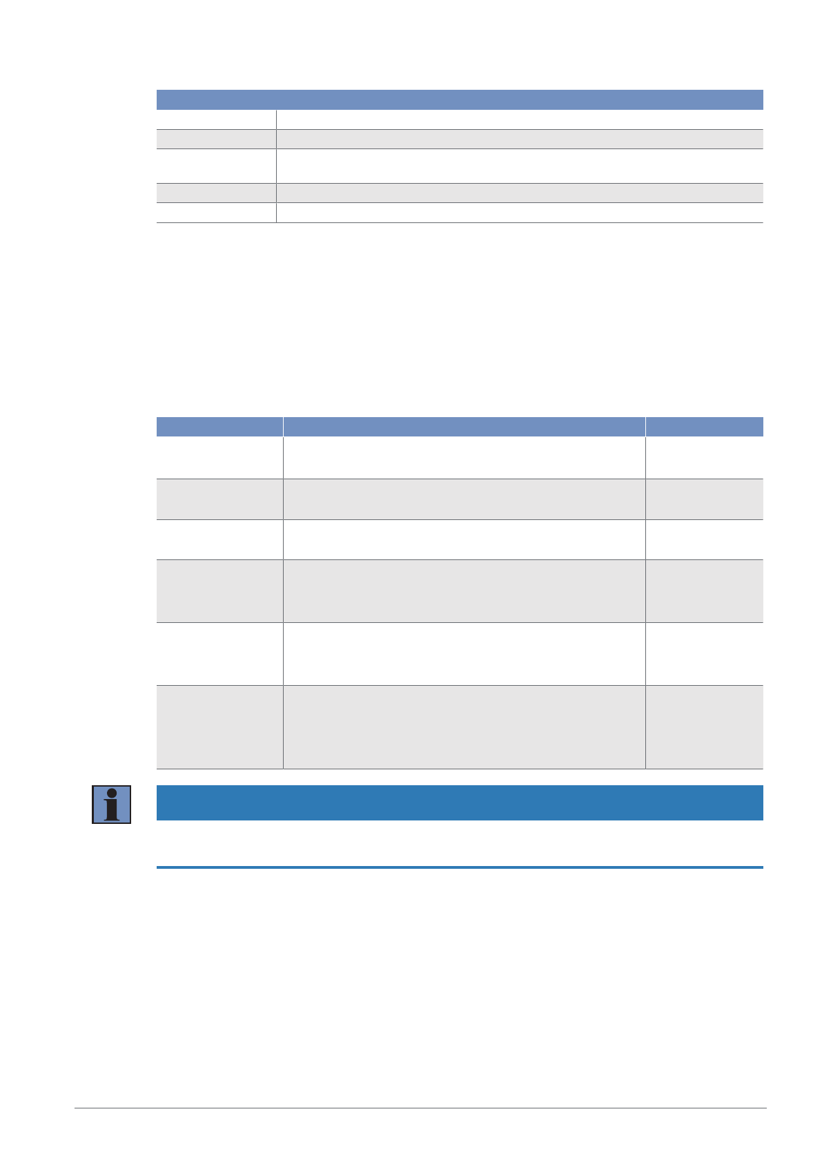
Status Messages
Warning
Undervoltage The supply voltage is too low.
Warning signal The object reflects too little light.
Ambient light Object detection is impeded by ambient light.
Overexposure The sensor signal is overexposed.
Temperature too
high
The sensor’s internal temperature is high.
Temperature too
low
The sensor’s internal temperature is low.
Emitted light off The sensor’s emitted light is switched off.
Error
Short circuit A short circuit has occurred on at least one pin.
No signal The sensor is not receiving a signal.
Page 38
8 ‒ Function Description | P3PC341 ‒ Laser Distance Sensor Triangulation 38
Error
Object too close The object is below the setting range or the set measuring range.
Object too far The object is above the setting range or the set measuring range.
Temperature error Temperature is outside permissible range. To protect the emitting unit, the emitted
light is switched off.
Device error A hardware error has occurred. For safety reasons, the emitted light is switched off.
Laser error There is an error in the laser module. For safety reasons, the laser is switched off.
8.8.3 Simulation Functions
This function simulates the behavior of the sensor regardless of the current status and measured value.
This can be used to check whether a plant in which the sensor is integrated reacts correctly to the data
supplied by the sensor and processes them accordingly.
If a measured value is specified, the sensor behaves as if the specified measured value corresponds to
the actual measured value. This means that the behavior of the outputs and status messages is simulated
according to the specified measured value.
In addition, the individual outputs and status messages can be simulated separately from the measured
value.
Function Possible settings Default
Simulation mode On
Off
Off
Test
measured value
Current measured value
min...max. measuring range
Current measured
value
Output O test According to the measured value
4…20 mA
According to the
measured value
SSC1 Test According to the measured value
On
Off
According to mea-
sured value
SSC2 Test According to the measured value
On
Off
According to mea-
sured value
Status messages test Tests the individual status messages
according to the measured value
On
Off
According to
measured value
INFORMATION
Output A1 is used for IO-Link communication in this function and cannot be simulated.
Simulation mode ends automatically as soon as the power supply is interrupted.
Page 39
9 ‒ Bluetooth | P3PC341 ‒ Laser Distance Sensor Triangulation 39
9 Bluetooth
These sensors have an integrated Bluetooth interface. This interface can be used to configure and param-
eterize devices using a smartphone and the wenglor “weCon” app. In addition, process data is sent to the
app, where it is displayed in a clear, concise manner.
9.1 weCon Installation
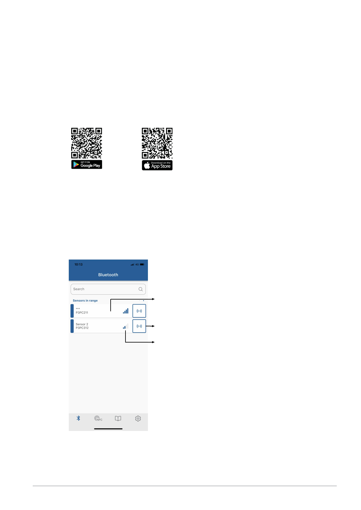
The wenglor app can be downloaded free of charge from the Google Play Store and Apple App Store.
Download the app and follow the installation instructions.
Scan the code below to access the wenglor app directly.
9.2 Establishing Connection with Sensor
Open the weCon app on your smartphone.
When the app is opened, all wenglor sensors with Bluetooth interface and within range are set to Pairing
mode.
This mode is indicated by the flashing blue LED on the sensors.
Pairing mode is used to pair the app with a corresponding sensor.
Once the app is opened, a list of all sensors within range is shown.
Connect to sensor
Bluetooth signal strength
Localization
If too many sensors of the same type are fitted within the Bluetooth range, the sensor’s supply voltage
LEDs can be switched to flashing green by pressing the “Localization” button. This simplifies identification.
Page 40
9 ‒ Bluetooth | P3PC341 ‒ Laser Distance Sensor Triangulation 40
Press the “Back” button to open the sensor list again. Pressing the “Connect with sensor” button estab-
lishes a connection to the sensor and opens the user interface.
The blue LED will continuously illuminate from now on, indicating that the sensor is paired, and Pairing
mode will deactivate.
9.3 Using the weCon App
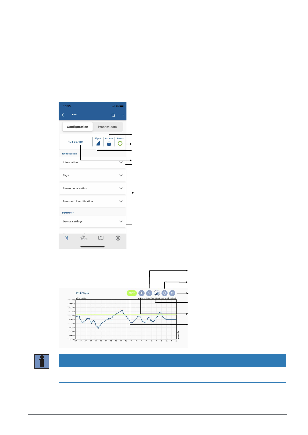
The sensor parameters are set in the "Configuration" tab. A detailed description of the individual parame-
ters can be found in the section Function Description [}24].
Bluetooth password function
Sensor status
Bluetooth signal strength
Current measured value
Parameters
The current measured value is displayed graphically in a diagram over time in the "Process Data" tab. The
scaling of the axes can be adjusted in the diagram settings.
Display legend
Show warnings/errors
Full screen mode on/off
Bluetooth signal strength
Enable auto zoom
Show switching threshold SSCx
NOTICE
The Bluetooth range is approximately 10 m. If the sensor is encapsulated in a system or installed close to
obstacles, the range may be reduced accordingly.
Page 41
10 ‒ IO-Link | P3PC341 ‒ Laser Distance Sensor Triangulation 41
10 IO-Link
The sensors can exchange parameters and process data via IO-Link. The parameters can be used to
make many additional settings on the device. The process data transmit cyclical data and condition moni-
toring.
To this end, the sensor is connected to a suitable IO-Link master (see product detail page/complementary
products). The interface protocol and the IODD can be found at www.wenglor.com in the download area
for the respective product.
10.1 Parameters
The parameters that can be configured via IO-Link are given in the functional description in the section
Function description [}24].
10.2 Condition Monitoring/Process Data
The data described in the following section can be read or written cyclically via IO-Link/process data.
10.2.1 Process Data In
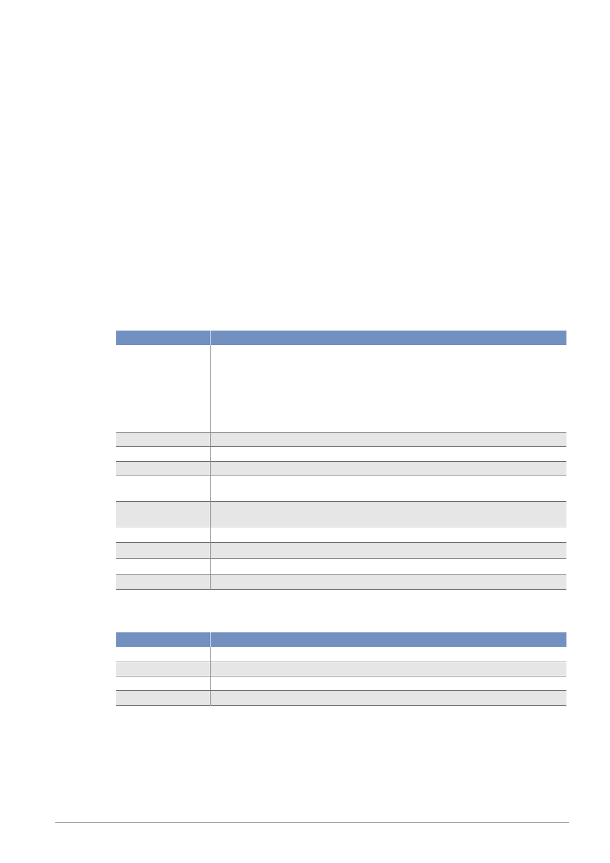
Data Meaning
Measured value Measured distance in micrometers or mil.
As the sensor cannot determine a measured value in the following error cases,
substitute values are read out:
No signal: 0x7FFFFFFC / 2147483644
Object too close: 0x80000008 / –2147483640
Object too far: 0x7FFFFFF8 / 2147483640
Scale Scaling of the measured value to the base length unit; -6 corresponds to μm.
SSC1 Switching point 1
SSC2 Switching point 2
Warning Collective warning in the event of one of the warning status messages (see table
“Status messages”) in the error output function)
Error Collective warning in the event of one of the error status messages (see table “Sta-
tus messages”) in error output function.
Message 1
Status message 1 read out see Status Message Function [}37]
Message 2
Status message 2 read out see Status Message Function [}37]
Message 3
Status message 3 read out see Status Message Function [}37]
Message 4
Status message 4 read out see Status Message Function [}37]
10.2.2 Process Data Out
Data Meaning
Emitted light Transmit signal on/off
Localization Sensor flashes for easy sensor location
Teach-in SSC1 Starts the teach-in process for SSC1
Teach-in SSC2 Starts the teach-in process for SSC2
10.2.3 Events
Events are diagnostic information that is standardized by IO-Link and exchanged between the IO-Link mas-
ter and the device. The following events are supported:
Page 42

10 ‒ IO-Link | P3PC341 ‒ Laser Distance Sensor Triangulation 42
Name Event code Type Specification
Maintenance necessary: Clean 0x8C40 Notifica-
tion
IO-Link
Device error – unknown error 0x1000 Error IO-Link
Short circuit – check installation 0x7710 Error IO-Link
Device temperature too high: Remove heat source 0x4210 Warning IO-Link
Device temperature too low: Isolate device 0x4220 Warning IO-Link
Temperature error: Overload 0x4000 Error IO-Link
Supply voltage too low – check tolerances 0x5111 Warning IO-Link
Page 43

11 ‒ wTeach2 Configuration Software | P3PC341 ‒ Laser Distance Sensor Triangulation 43
11 wTeach2 Configuration Software
For information on installing and connecting the wTeach2 software and its structure, as well as information
on the general functions, see the wTeach2 operating instructions. They can be found online in the down-
load area at www.wenglor.com under order number DNNF005.
The wTeach2 operating software can be used to configure all functions, in accordance with the function
description [}24], and read out the IO-Link process data.
In addition, there are functions that are only available via wTeach. These are described in the following
sections.
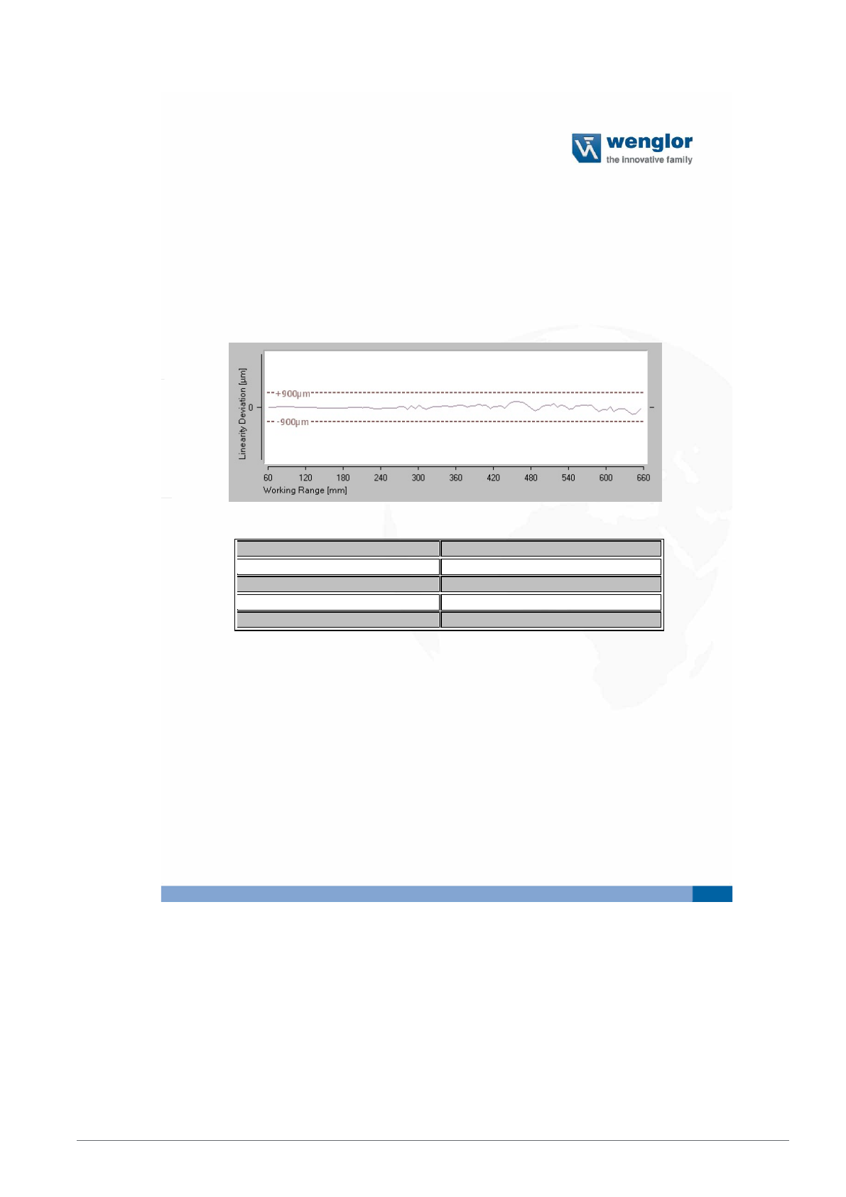
11.1 Calling Up the Calibration Protocol
To access the sensor-specific calibration protocol, click on the corresponding icon in the
menu bar.
Page 44
11 ‒ wTeach2 Configuration Software | P3PC341 ‒ Laser Distance Sensor Triangulation 44
Calibraon Protocol
Laser Distance Sensor Triangulaon
Supplier: wenglor sensoric GmbH
Order Number: P3PC312
Serial Number: 750126317
Measurement Conditions
Working Range 60 ... 660 mm
Linearity Deviation 900µm
Measured Surface White
(
90%
)
lambertian
Filter 3
(
default
)
Sensor warmed up >5min
Differences of these Data can appear because of:
-
Target material and surface
-
Sensor mounting
(
tilt
)
-
Temperature fluctuation du ring the measurement
-
Circulation of warm air between sensor and target
-
Ambient light
Docu ment was created electronically and thus valid without signature
Inspector: wenglor
Data: 06.04.2023
A window opens to select the location for saving the PDF document. After selection and confirmation, the
document is saved accordingly.
Page 45

12 ‒ Maintenance Instructions | P3PC341 ‒ Laser Distance Sensor Triangulation 45
12 Maintenance Instructions
NOTICE
This wenglor product is maintenance-free.
Cleaning and inspection of the plug connections at regular intervals are advisable.
Do not clean the product with solvents or cleaning agents that could damage the product.
The product must be protected against contamination during initial start-up.
Page 46

13 ‒ Proper Disposal | P3PC341 ‒ Laser Distance Sensor Triangulation 46
13 Proper Disposal
wenglor sensoric GmbH does not accept the return of unusable or irreparable products. Respectively
valid national waste disposal regulations apply to product disposal.
Page 47

14 ‒ Declarations of Conformity | P3PC341 ‒ Laser Distance Sensor Triangulation 47
14 Declarations of Conformity
Declarations of conformity can be found on our website at www.wenglor.com in the product’s separate
download area.
 Loading...