

Page 1
9-INCH BENCHTOP
BAND SAW
Model # 3960
bit.ly/wenvideo
IMPORTANT:
Your new tool has been engineered and manufactured to WEN’s highest standards for dependability,
ease of operation, and operator safety. When properly cared for, this product will supply you years
of rugged, trouble-free performance. Pay close attention to the rules for safe operation, warnings,
and cautions. If you use your tool properly and for intended purpose, you will enjoy years of safe,
reliable service.
NEED HELP? CONTACT US!
Have product questions? Need technical support?
Please feel free to contact us at:
800-232-1195
(M-F 8AM-5PM CST)
techsupport@wenproducts.com
WENPRODUCTS.COM
Page 2

TABLE OF CONTENTS
Technical Data
General Safety Rules
Specific Safety Rules For Band Saw
Electrical Information
Assembly
Adjustments
Operation
Maintenance
Exploded View & Parts List
Warranty
TECHNICAL DATA
2
3
4
5
7
9
12
13
14
17
Model Number:
Motor:
Throat:
Cutting Depth:
Speeds:
Table Angle:
Work Table:
Blade Length:
Blade Width:
Weight:
2
120 V, 60 Hz, 300W, 2.8A
3-5/8 inches
0 to 45 degrees
12 x 12 inches
1/8 to 3/8 inches
3960
9 inches
2460 FPM
62 inches
44 pounds
Page 3

GENERAL SAFETY RULES
Safety is a combination of common sense, staying alert and knowing how your item works. SAVE THESE SAFE-
TY INSTRUCTIONS.
WARNING: To avoid mistakes and serious injury, do not plug in your tool until the following steps
have been read and understood.
1. READ and become familiar with this entire instruction manual. LEARN the tool’s applications, limitations, and
possible hazards.
2. AVOID DANGEROUS CONDITIONS. Do not use power tools in wet or damp areas or expose them to rain.
Keep work areas well lit.
3. DO NOT use power tools in the presence of flammable liquids or gases.
4. ALWAYS keep your work area clean, uncluttered, and well lit. DO NOT work on floor surfaces that are slippery
with sawdust or wax.
5. KEEP BYSTANDERS AT A SAFE DISTANCE from the work area, especially when the tool is operating.
NEVER allow children or pets near the tool.
6. DO NOT FORCE THE TOOL to do a job for which it was not designed.
7. DRESS FOR SAFETY. Do not wear loose clothing, gloves, neckties, or jewelry (rings, watches, etc.) when operating the tool. Inappropriate clothing and items can get caught in moving parts and draw you in. ALWAYS wear
non-slip footwear and tie back long hair.
8. WEAR A FACE MASK OR DUST MASK to fight the dust produced by sawing operations.
WARNING: Dust generated from certain materials can be hazardous to your health. Always operate the
tool in a well-ventilated area and provide for proper dust removal. Use dust collection systems whenever
possible.
9. ALWAYS remove the power cord plug from the electrical outlet when making adjustments, changing parts,
cleaning, or working on the tool.
10. KEEP GUARDS IN PLACE AND IN WORKING ORDER.
11. AVOID ACCIDENTAL START-UPS. Make sure the power switch is in the OFF position before plugging in
the power cord.
12. REMOVE ADJUSTMENT TOOLS. Always make sure all adjustment tools are removed from the saw before
turning it on.
13. NEVER LEAVE A RUNNING TOOL UNATTENDED. Turn the power switch to OFF. Do not leave the
tool until it has come to a complete stop.
14. NEVER STAND ON A TOOL. Serious injury could result if the tool tips or is accidentally hit. DO NOT store
anything above or near the tool.
3
Page 4

GENERAL SAFETY RULES
15. DO NOT OVERREACH. Keep proper footing and balance at all times. Wear oil-resistant rubber-soled footwear. Keep the floor clear of oil, scrap, and other debris.
16. MAINTAIN TOOLS PROPERLY. ALWAYS keep tools clean and in good working order. Follow instructions for lubricating and changing accessories.
17. CHECK FOR DAMAGED PARTS. Check for alignment of moving parts, jamming, breakage, improper
mounting, or any other conditions that may affect the tool’s operation. Any part that is damaged should be properly
repaired or replaced before use.
18. MAKE THE WORKSHOP CHILDPROOF. Use padlocks and master switches and ALWAYS remove starter keys.
19. DO NOT operate the tool if you are under the influence of drugs, alcohol, or medication that may affect your
ability to properly use the tool.
20. USE SAFETY GOGGLES AT ALL TIMES that comply with ANSI Z87.1. Normal safety glasses only have
impact resistant lenses and are not designed for safety. Wear a face or dust mask when working in a dusty environment. Use ear protection such as plugs or muffs during extended periods of operation.
SPECIFIC RULES FOR BAND SAW
1. To avoid injury from unexpected movement, make sure the saw is on a firm, level surface, properly secured to
prevent rocking. Make sure there is adequate space for operations. Bolt the saw to a support surface to prevent slipping or sliding during operation.
2. Turn off and unplug the saw before moving it.
3. Use the correct size and style of blade.
4. Make sure the blade teeth point down and toward the table.
5. Blade guide, supports, bearings, and blade tension must be properly adjusted to avoid accidental blade contact
and to minimize blade breakage. To maximize blade support, always adjust the upper blade guide and blade guard
so that it barely clears the workpiece.
6. Table TILT lock handle should be tight and locked during operation.
7. Use extra caution with very large, very small, or awkwardly-shaped workpieces.
8. Use extra supports to prevent workpieces from sliding off the tabletop.
9. Workpieces should be secured so they don’t twist, rock, or slip while being cut.
10. Plan intricate or small work carefully to avoid pinching the blade. Avoid awkward operations and hand positions
to prevent accidental contact with the blade.
4
Page 5
SPECIFIC RULES FOR BAND SAW
11. Small pieces should be secured with clamps or fixtures. Do not hold small pieces with your hand because your
fingers might go under the blade guard.
12. Support round work properly (use a V block or press it against the miter gauge) to prevent it from rolling and
the blade from biting.
13. Cut only one workpiece at a time. Make sure the table is clear of everything except the workpiece and its guides
before you turn the saw on.
14. Always WATCH the saw run before each use. If there is excessive vibration or unusual noise, stop immediately.
Turn the saw off. Unplug it immediately. Do not start the saw again until the problem has been located and corrected.
15. To free any jammed material, turn the switch off. Remove the switch key and unplug the saw. Wait for all moving parts to stop before removing the jammed material.
16. Don’t leave the work area until all moving parts have stopped. Shut off the power to master switches. Remove
the switch key from the band saw and store it in a safe place, away from children. Childproof the workshop!
ELECTRICAL INFORMATION
GROUNDING INSTRUCTIONS
IN THE EVENT OF A MALFUNCTION OR BREAKDOWN, grounding provides the path of least resistance
for an electric current and reduces the risk of electric shock. This tool is equipped with an electric cord that has an
equipment grounding conductor and a grounding plug. The plug MUST be plugged into a matching outlet that is
properly installed and grounded in accordance with ALL local codes and ordinances.
DO NOT MODIFY THE PLUG PROVIDED. If it will not fit the outlet, have the proper outlet installed by a
licensed electrician.
IMPROPER CONNECTION of the equipment grounding conductor can result in electric shock. The conductor with the green insulation (with or without yellow stripes) is the equipment grounding conductor. If repair or
replacement of the electric cord or plug is necessary, DO NOT connect the equipment grounding conductor to a
live terminal.
CHECK with a licensed electrician or service personnel if you do not completely understand the grounding instructions or whether the tool is properly
grounded.
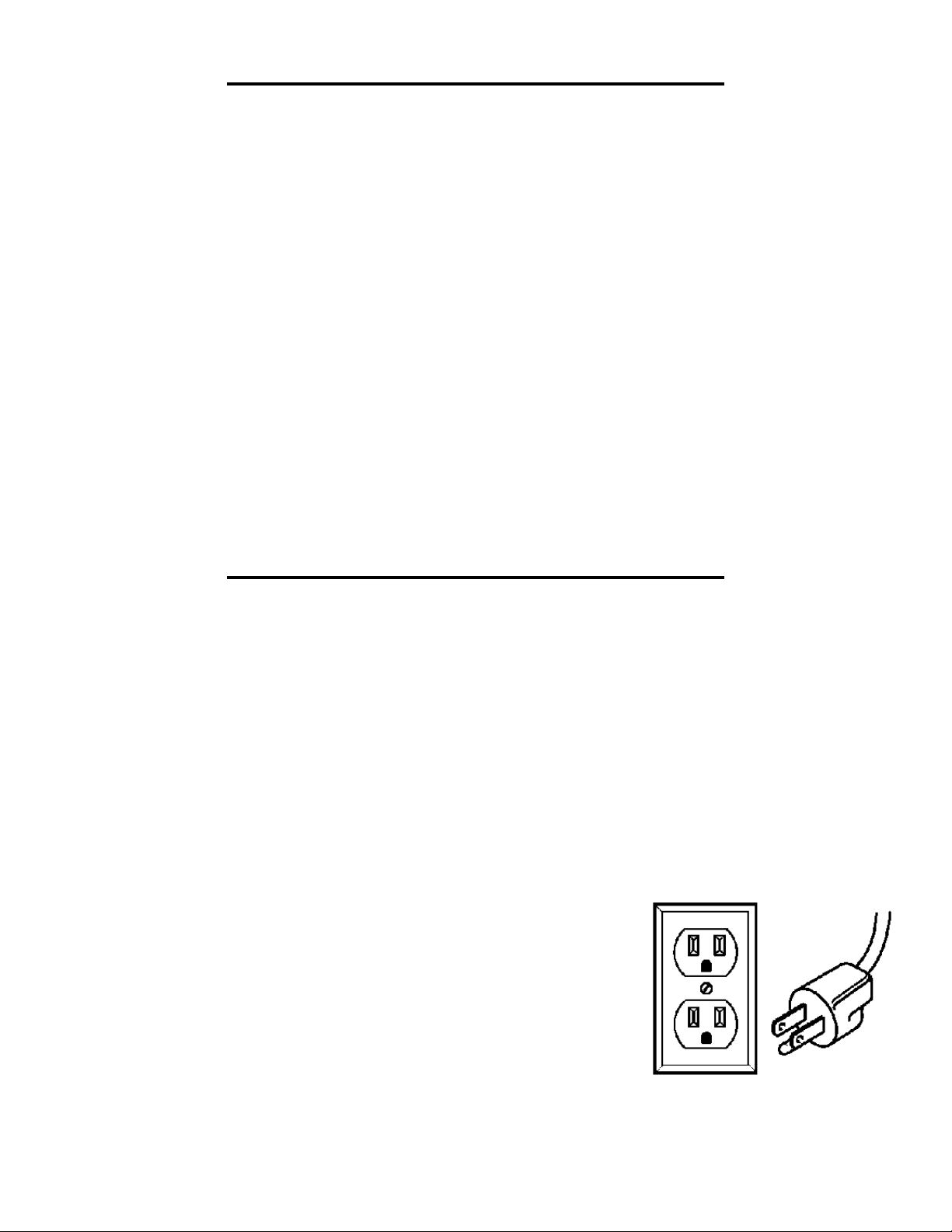
USE ONLY THREE-WIRE EXTENSION CORDS that have three-pronged
plugs and outlets that accept the tool’s plug as shown in Fig. A. Repair or replace a damaged or worn cord immediately.
CAUTION: In all cases, make certain the outlet in question is properly grounded. If you are not sure, have a licensed electrician check the outlet.
FIGURE A
5
Page 6
ELECTRICAL INFORMATION
WARNING: This tool is for indoor use only. Do not expose to rain or use in damp locations.
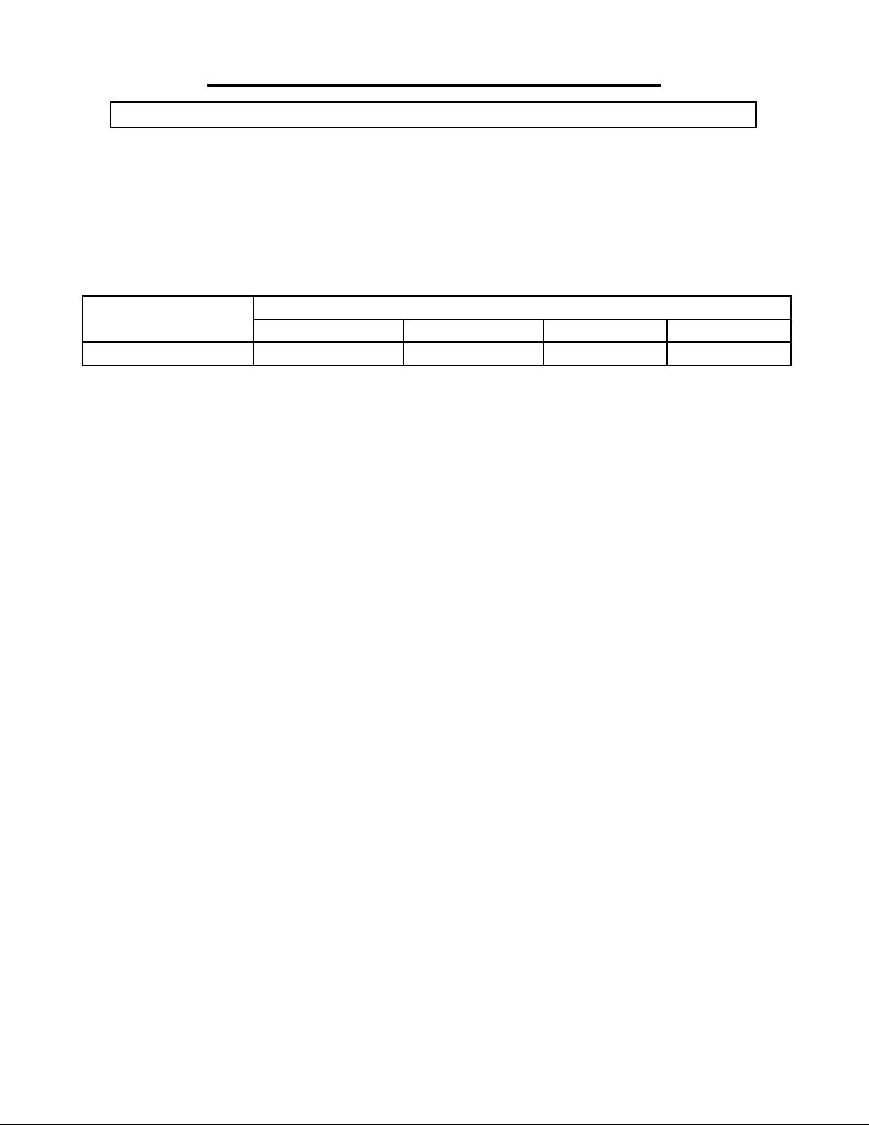
UL GUIDELINES AND RECOMMENDATIONS FOR EXTENSION CORDS
Make sure your extension cord is in good condition. When using an extension cord, be sure to use one heavy
enough to carry the current your product will draw. An undersized cord will cause a drop in line voltage resulting
in loss of power and overheating. The table below shows the correct size to be used according to cord length and
nameplate ampere rating. When in doubt, use a heavier cord. The smaller the gauge number, the heavier the cord.
AMPERAGE
2.8 A 18 gauge 16 gauge 16 gauge 14 gauge
Make sure your extension cord is properly wired and in good condition. Always replace a damaged extension cord
or have it repaired by a qualified person before using it.
Protect your extension cords from sharp objects, excessive heat and damp/wet areas.
Use a separate electrical circuit for your tools. This circuit must not be less than a #12 wire and should be protected
with a 15 A time-delayed fuse. Before connecting the motor to the power line, make sure the switch is in the OFF
position and the electric current is rated the same as the current stamped on the motor nameplate. Running at a
lower voltage will damage the motor.
WARNING: This tool must be grounded while in use to protect the operator from electric shock.
REQUIRED GAUGE FOR EXTENSION CORDS
25 ft. 50 ft. 100 ft. 150 ft.
6
Page 7

ASSEMBLY
UNPACKING
Carefully unpack the band saw and all its parts, and compare against the list below. Do not discard the carton or
any packaging until the band saw is completely assembled.
WARNING: If any part is missing or damaged, do not plug in the band saw until the missing or damaged part is replaced.
2
1
4
5
6
3
1. Band Saw (1)
2. Fence (1)
3. Table Assembly (1)
4. Open Spanner (1)
7
5. 6mm Hex Wrench (1)
6. 4mm Hex Wrench (1)
7. Miter Gauge (1)
8. Feet (4)
8
WARNING: For your own safety, read the instruction manual before operating the band saw.
1. Wear eye protection.
2. Do not wear gloves, a necktie, jewelry, or loose clothing.
3. Make sure the saw is on a firm, level surface and properly secured.
4. Use only the recommended accessories.
5. Use extra caution with very large, very small, or awkward workpieces.
6. Keep hands away from blade at all times to prevent accidental injury.
7
Page 8

ASSEMBLY
WARNING: Unplug the machine from the power source before assembling or making
adjustments. Failure to comply may cause serious injury. Assembly requires at least two
people to safely move around the band saw.
HOW TO ASSEMBLE
1. Attach the four feet to the base of the band saw (Fig. A).
2. Remove the D-nut (Fig. B - 1), washers (Fig. B - 2) and wing screw (Fig.
B - 3) from the saw’s table assembly (Fig. B).
3. Slide the saw table onto the band saw (Fig. C), making sure that the
blade stays within the slot. Pull the angle adjustment knob back(Fig. D -
2) and align the teeth on the saw blade’s table bracket into the teeth on
the angle adjustment knob. Release the knob.
4. Fit the pins on the frame into the slots of the table bracket (Fig. D - 3).
5. Assemble the flat washer and table lock handle (Fig. D - 1). Tighten
the table assembly to the saw’s frame by turning the table lock lever clockwise.
6. Fix the band saw to a workbench by using the four screws (not provided, Fig. E - 3) through the holes in the base of the band saw (Fig. E).
7. Place the fence (Fig. E - 1) and the miter gauge onto the table (Fig. E -
2).
2
Fig. B
Fig. A
1
3
Fig. C
1
2
1
2
3
Fig. D
88
3
Fig. E
Page 9

ADJUSTMENTS
WARNING: Always be sure that the tool is switched off and unplugged before making any adjustments.
TILTING THE TABLE
1. Find and loosen the table bevel lock located in back under the
saw table (Fig. F - 2).
2. Adjust the table to the desired angle using the table tilting knob
(Fig. F - 1) and the angle indicator.
3. Use the angle indicator to confirm the desired angle and tighten
the lock handle (NOTE: a table perpendicular (90°) to the blade
corresponds to a scale indication of 0°).
Fig. F
ADJUSTING THE SAW BLADE
If the blade does not run in the middle of the rubber tire band, the tracking needs to be corrected by adjusting the
tilt of the upper band saw wheel.
1. Turn off the band saw and unplug it from the power supply. Open both the upper and lower wheel covers once
the blade has stopped moving (Fig. G).
2. Manually rotate the upper wheel, making sure not to touch the blade. Watch to see which direction the blade
tends to veer off towards in order to best adjust the tracking set knob to resolve the problem.
3. Turn tracking set knob (Fig. H - 2) in the desired direction until the blade is centered over the upper and lower
wheels.
1
2
4. Spin the wheel manually to ensure that the blade is now running in the center. Close the covers.
1
Fig. G Fig. H
2
9
Page 10

ADJUSTMENTS
ADJUSTING BLADE TENSION
WARNING: If the tension in the blade is too high, it runs the risk of breaking. If the tension is too low,
there is a risk of the blade slipping and stopping during a cut.
1. Raise the upper blade guide fully using the upper blade guide adjustment knob (Fig. I - 1).
2. Check the tension by pushing with a finger against the side of the blade halfway between the table and the upper
guide. The blade should not flex more than 2 mm.
3. Turn the tension knob (Fig. H - 1) clockwise to increase the blade tension or counterclockwise to decrease tension. Take the blade width into consideration during the adjustment.
UPPER BLADE GUIDE ADJUSTMENT
The height of the upper blade guard should be adjusted prior to every operation to accommodate the height of
the workpiece (the blade guard should be no more than one-eighth of an inch from the upper edge of the workpiece).
1. Loosen the upper blade guide locking knob located on the back of the drill press (Fig. I - 2). Turn the adjustment knob (Fig. I - 1) to adjust the height of the upper blade guide. Relock the upper blade guide locking knob to
secure the guard in place once the desired height has been reached.
2. Loosen the lower screw (Fig. I - 3) to adjust the guide bearings running along either side of the band saw blade.
The guide bearings should be positioned 1 to 2 mm from the teeth of the blade (Fig. K). Retighten the screw
afterward.
3. Loosen the upper screw (Fig. I - 4) and adjust the thrust bearing running along the back of the blade (Fig. K).
This bearing should be positioned 1/2 mm from the back of the blade. Retighten the screw afterward.
4. Loosen the socket head screw (Fig. J - 1) to adjust the guide bearings 1/4 mm away from the blade (Fig. L).
Retighten the socket head screw.
1
2
10
4
3
Fig. I
1
Fig. J
Page 11

ADJUSTMENTS
LOWER BLADE GUIDE ADJUSTMENT
The lower blade guide needs to be readjusted after every band saw blade change or tracking adjustment.
1. Use a hex wrench to loosen the socket bolts in Holes 1 & 2 (Fig. M - 1, 2). Adjust the guide block (Fig. M - 4)
and thrust bearing (Fig. M - 3) in the same manner that you adjusted the upper blade guide.
2. Loosen Screw 1 (Fig. M - 5) and adjust the guide bearing to a position of 1/4 mm away from the blade. Retighten Screw 1 (Fig. M - 5).
5
34
Fig. K
CHANGING THE BAND SAW BLADE
WARNING: Saw blades are dangerous. Be sure to always wear gloves while handling the blade or
removing it from packaging.
1. Remove the D-nut (Fig. B - 1), washers (Fig. B - 2) and wing screw (Fig. B - 3) from the saw’s table assembly
(Fig. B).
2. Open the upper and lower blade covers (Fig. G).
3. Set the upper blade guide to its lowest position, minimizing the space between the bottom of the upper blade
guide and the table assembly.
4. Open the cover of the upper guide assembly
Fig. L
1
2
Fig. M
5. Loosen the tension knob (Fig. H - 1) until you can remove the blade from the machine.
6. Fit the fresh blade in the center of the rubber tires of the band saw wheels. Retighten the tension knob (Fig. H -
1).
7. Replace the D-nut (Fig. B - 1), washers (Fig. B - 2) and wing screw (Fig. B - 3) from the saw’s table assembly
(Fig. B).
8. Close the upper and lower covers along with the cover of the upper guide assembly.
9. Adjust the alignment of the blade, the blade tension, and the upper and lower blade guides as needed.
11
Page 12

OPERATION
SUGGESTIONS AND WARNINGS:
• Do not touch the saw blade when cutting.
• During saw operation, wear safety glasses but do not wear gloves.
• Cut only one workpiece at a time.
• Always hold the workpiece down on the table.
• Do not jam any workpieces.
• Do not try to slow the blade down by pushing the work piece against the saw blade from the side.
• When straight cutting against the fence, use a push stick.
• Use a work support when cutting long stock to avoid pieces from falling down after the cut has
been completed.
• Use a dust collector to minimize sawdust.
• When cutting round stock, make sure the piece is as secure as possible.
• Before starting, check that the saw blade and the upper and lower blade guides are in proper
working order.
• Replace damaged parts immediately.
• Assume the correct working position (the blade’s teeth should be pointing towards the operator).
• Take all necessary precautions to avoid kickback during operation.
ON/OFF SWITCH
1. To turn the saw ON, move the switch to the up position (Fig. N - 1).
2. To turn the saw OFF, move the switch to the down (OFF) position.
3. To lock the switch in the OFF position:
A) Wait until the band saw has come to a complete stop.
B) Remove the safety key from the switch housing. Store the safety
key in a safe place.
4. To unlock the switch and turn the saw ON, insert the safety key into
the switch, and move the switch to the ON position.
USING THE MITER GAUGE
1. Place the miter gauge into the slot on the table. (Fig. O)
2. Loosen the knob on the gauge to set a new miter angle (between 0
and 60 degrees).
1
Fig. N
12
Fig. O
3. Tighten the knob firmly before cutting begins.
NOTE: A 0° cut is a straight cut that is perpendicular to the blade.
Page 13
OPERATION
GENERAL CUTTING
WARNING: Operating a band saw involves a certain
amount of hazard. Read the instructions and plan your work
1
before cutting a workpiece.
1. Use scrap lumber to check the settings and to get the feel of operating the band saw before attempting regular work.
Fig. O
keep the upper blade guard close to your work, approximately 1/8 of an inch above the workpiece.
3. Do not force the workpiece against the blade. Light contact permits easier cutting and prevents unwanted
friction and heating of the blade. Sharp saw blades need little pressure for cutting. Steadily move the workpiece
against the blade without forcing it.
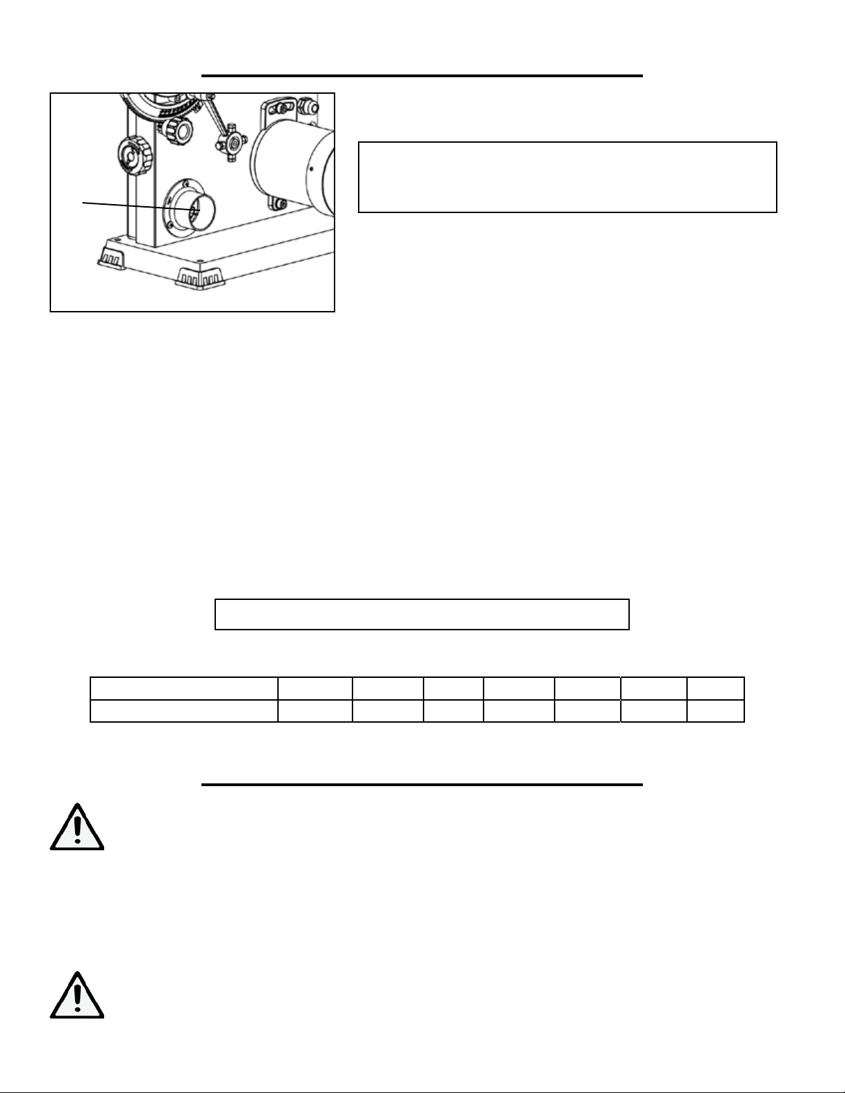
4. It is recommended that a dust collector be connected to the 2-inch dust port when sawing wood (Fig. O - 1).
5. Use the band saw for straight line operations such as cross-cutting, ripping, miter cutting, beveling, compound
cutting, and resawing.
6. To avoid twisting the blade, do not turn sharp corners; instead, saw around corners. A band saw is basically a
“curve-cutting” saw. It is not capable of doing intricate inside cutting as can be done with a scroll saw.
WARNING: Do not use this band saw to cut ferrous metals.
BLADE WIDTH 1/8 in. 3/16 in. 1/4 in. 3/8 in. 1/2 in. 3/4 in. 1 in.
MINIMUM RADIUS 3/16 in. 5/16 in. 5/8 in. 1-1/2 in. 2-1/2 in. 5-1/2 in. 7 in.
2. Do not turn the power on until all adjustments have been made.
Check to make sure the upper and lower guard are in place. Always
CIRCLE CUTTING GUIDE
MAINTENANCE
WARNING: For your own safety, turn the switch OFF and remove the plug from the electrical outlet
before performing maintenance or lubricating the band saw.
1. Routinely remove the sawdust from the inside of the housing. Blow out the sawdust from the motor.
2. Clean off the pitch which accumulates on the table, blade guides, and bearings.
3. Remove pitch and dust from the upper and lower wheels using a stiff brush. Do not use solvents.
4. Apply a thin coat of automotive polish to the table top for a slick surface.
5. Replace blades and the wheel tires when worn.
WARNING: Replace the power cord immediately if it is worn, cut, or damaged in any way.
13
Page 14

EXPLODED VIEW & PARTS LIST
14
Page 15

NO. PART DESCRIPTION QTY
NO. PART DESCRIPTION QTY
1 3960-001 Blade Tension Knob 1
2 3960-002 Flat Washer 1
3 3960-003 Blade Tension Spring 1
4 3960-004 Carriage Bolt 1
5 3960-005 Pulling Plate 1
6 3960-006 Socket Head Screw 1
7 3960-007 Shaft 1
8 3960-008 Lock Catch 2
9 3960-009 Hex Nut 1
10 3960-010 Lock Washer 1
11 3960-011 Bevel Support Plate 1
12 3960-012 Upper Wheel Shaft 1
13 3960-013 Ball Bearing (6000ZZ) 4
14 3960-014 Upper Wheel 1
15 3960-015 Int. Retaining Ring 4
16 3960-016 Ext. Retaining Ring 2
17 3960-017 Tire 2
18 3960-018 Upper Wheel Cover 1
19 3960-019 Blade 1
20 3960-020 Lower Wheel Cover 1
21 3960-021 Lock Nut 2
22 3960-022 Bushing 2
23 3960-023 Socket Head Screw 2
24 3960-024 Lower Wheel 1
25 3960-025 Thread Forming Screw 3
26 3960-026 Drive Pulley 1
27 3960-027 Lower Wheel Shaft 1
28 3960-028 Hex Nut 4
29 3960-029 Hex Bolt 4
EXPLODED VIEW & PARTS LIST
30 3960-030 Lock Nut 1
31 3960-031 Lifting Handle 1
32 3960-032 Pan Head Screw 2
33 3960-033 Frame 1
34 3960-034 Switch Box 1
35 3960-035 Pan Head Screw 2
36 3960-036 Switch Mounting Plate 1
37 3960-037 Thread Forming Screw 1
38 3960-038 Switch 1
39 3960-039 Lock Washer 2
40 3960-040 Serrated Washer 2
41 3960-041 Pan Head Screw 2
42 3960-042 Hex Nut 1
43 3960-043 Flat Washer 2
44 3960-044 Bushing 1
45 3960-045 Brush 1
46 3960-046 Carriage Blot 1
47 3960-047 Foot 4
48 3960-048 Belt 1
49 3960-049 Dust Port 1
50 3960-050 Pan Head Screw 3
51 3960-051 Lock Nut 2
52 3960-052 Catching Knob 2
53 3960-053 Socket Head Screw 2
54 3960-054 Socket Head Screw 2
55 3960-055 Ball Bearing (606ZZ) 2
56 3960-056 Flat Washer 2
57 3960-057 Support Rod 1
58 3960-058 Socket Head Screw 4
59 3960-059 Ball Bearing (605ZZ) 4
60 3960-060 Flat Washer 4
61 3960-061 Lower Guide Block 1
62 3960-062 Square Nut 4
63 3960-063 Support Block 1
64 3960-064 Socket Head Screw 2
65 3960-065 Flat Washer 2
66 3960-066 Socket Head Screw 2
67 3960-067 Lower Protecting Cover 1
68 3960-068 Flat Washer 2
69 3960-069 Pan Head Screw 2
70 3960-070 Strain Relief 2
71 3960-071 Guide Plate 1
72 3960-072 Set Screw 1
73 3960-073 Pinion 1
74 3960-074 Adjustment Knob Seat 1
75 3960-075 Flat Washer 1
76 3960-076 Socket Head Screw 2
77 3960-077 Adjustment Knob 1
78 3960-078 Upper Guide Block 1
79 3960-079 Support Rod 1
80 3960-080 Flat Washer 2
81 3960-081 Socket Head Screw 1
82 3960-082 Socket Head Screw 1
83 3960-083 Flat Washer 2
84 3960-084 Socket Head Screw 2
85 3960-085 Upper Cover Assembly 1
86 3960-086 Square Nut 1
87 3960-087 Guide Block 1
88 3960-088 Flat Washer 2
89 3960-089 Socket Head Screw 2
90 3960-090 Flat Washer 8mm 1
15
Page 16

NO. PART DESCRIPTION QTY
NO. PART DESCRIPTION
QTY
91 3960-091 Locking Knob 1
92 3960-092 Flat Washer 8mm 2
93 3960-093 Spring 1
94 3960-094 Tracking Knob 1
95 3960-095 Socket Head Screw 1
96 3960-096 Release Block 1
97 3960-097 Socked Head Screw 1
98 3960-098 Limiting Screw 1
99 3960-099 Sleeve 1
100 3960-100 Wave Washer 1
101 3960-101 Shaft 1
102 3960-102 Set Screw 1
103 3960-103 Release Handle 1
91 3960-091 Locking Knob 1
EXPLODED VIEW & PARTS LIST
104 3960-104 Miter Gauge Assembly 1
105 3960-105 Table Insert 1
106 3960-106 Table 1
107 3960-107 D Nut 1
108 3960-108 Flat Washer 1
109 3960-109 Wing Screw 1
110 3960-110 Hex Nut 1
111 3960-111 Hex Bolt 1
112 3960-112 Bevel Case 1
113 3960-113 Flat Washer 4
114 3960-114 Socket Head Screw 4
115 3960-115 Guide Bushing 2
116 3960-116 Socket Head Screw 2
117 3960-117 Flat Washer 1
118 3960-118 Locking Handle 1
119 3960-119 Pointer 1
120 3960-120 Flat Washer 1
121 3960-121 Pan Head Screw 1
122 3960-122 Table Adjusting Handle 1
123 3960-123 Spring 1
124 3960-124 Bolt 1
125 3960-125 Motor 1
126 3960-126 Sponge Ring 1
127 3960-127 Motor Pully 1
128 3960-128 Flat Washer 1
129 3960-129 Socket Head Screw 1
130 3960-130 Flat Washer 8mm 2
131 3960-131 Socket Head Screw 2
132 3960-132 Power Cord 1
133 3960-133 Fence Assembly 1
134 3960-134 Open Spanner 1
135 3960-135 Hex Wrench 2
16
Page 17

LIMITED TWO YEAR WARRANTY
WEN Products is committed to build tools that are dependable for years. Our warranties are consistent with this
commitment and our dedication to quality.
LIMITED WARRANTY OF WEN CONSUMER POWER TOOLS PRODUCTS FOR HOME USE
GREAT LAKES TECHNOLOGIES, LLC (“Seller”) warrants to the original purchaser only, that all WEN consumer power tools will be free from defects in material or workmanship for a period of two (2) years from date of
purchase. Ninety days for all WEN products, if the tool is used for professional use.
SELLER’S SOLE OBLIGATION AND YOUR EXCLUSIVE REMEDY under this Limited Warranty and, to
the extent permitted by law, any warranty or condition implied by law, shall be the repair or replacement of parts,
without charge, which are defective in material or workmanship and which have not been misused, carelessly
handled, or misrepaired by persons other than Seller or Authorized Service Center. To make a claim under this
Limited Warranty, you must make sure to keep a copy of your proof of purchase that clearly defines the Date of
Purchase (month and year) and the Place of Purchase. Place of purchase must be a direct vendor of Great Lakes
Technologies, LLC. Third party vendors such as garage sales, pawn shops, resale shops, or any other secondhand
merchant void the warranty included with this product. Contact techsupport@wenproducts.com or 1-800-2321195 to make arrangements for repairs and transportation.
When returning a product for warranty service, the shipping charges must be prepaid by the purchaser. The product must be shipped in its original container (or an equivalent), properly packed to withstand the hazards of shipment. The product must be fully insured with a copy of the warranty card and/or the proof of purchase enclosed.
There must also be a description of the problem in order to help our repairs department diagnose and fix the
issue. Repairs will be made and the product will be returned and shipped back to the purchaser at no charge.
THIS LIMITED WARRANTY DOES NOT APPLY TO ACCESSORY ITEMS THAT WEAR OUT FROM
REGULAR USAGE OVER TIME INCLUDING BELTS, BRUSHES, BLADES, ETC.
ANY IMPLIED WARRANTIES SHALL BE LIMITED IN DURATION TO ONE (1) YEAR FROM DATE
OF PURCHASE. SOME STATES IN THE U.S., SOME CANADIAN PROVINCES DO NOT ALLOW
LIMITATIONS ON HOW LONG AN IMPLIED WARRANTY LASTS, SO THE ABOVE LIMITATION
MAY NOT APPLY TO YOU.
IN NO EVENT SHALL SELLER BE LIABLE FOR ANY INCIDENTAL OR CONSEQUENTIAL DAMAGES (INCLUDING BUT NOT LIMITED TO LIABILITY FOR LOSS OF PROFITS) ARISING FROM
THE SALE OR USE OF THIS PRODUCT. SOME STATES IN THE U.S. AND SOME CANADIAN
PROVINCES DO NOT ALLOW THE EXCLUSION OR LIMITATION OF INCIDENTAL OR CONSEQUENTIAL DAMAGES, SO THE ABOVE LIMITATION OR EXCLUSION MAY NOT APPLY TO
YOU.
THIS LIMITED WARRANTY GIVES YOU SPECIFIC LEGAL RIGHTS, AND YOU MAY ALSO HAVE
OTHER RIGHTS WHICH VARY FROM STATE TO STATE IN THE U.S., PROVINCE TO PROVINCE
IN CANADA AND FROM COUNTRY TO COUNTRY.
THIS LIMITED WARRANTY APPLIES ONLY TO PORTABLE ELECTRIC TOOLS, BENCH POWER TOOLS, OUTDOOR POWER EQUIPMENT AND PNEUMATIC TOOLS SOLD WITHIN THE
UNITED STATES OF AMERICA, CANADA AND THE COMMONWEALTH OF PUERTO RICO. FOR
WARRANTY COVERAGE WITHIN OTHER COUNTRIES, CONTACT THE WEN CUSTOMER SUPPORT LINE.
17
Page 18

THANKS FOR
REMEMBERING
18
 Loading...