

Wen 3500 Generator Section
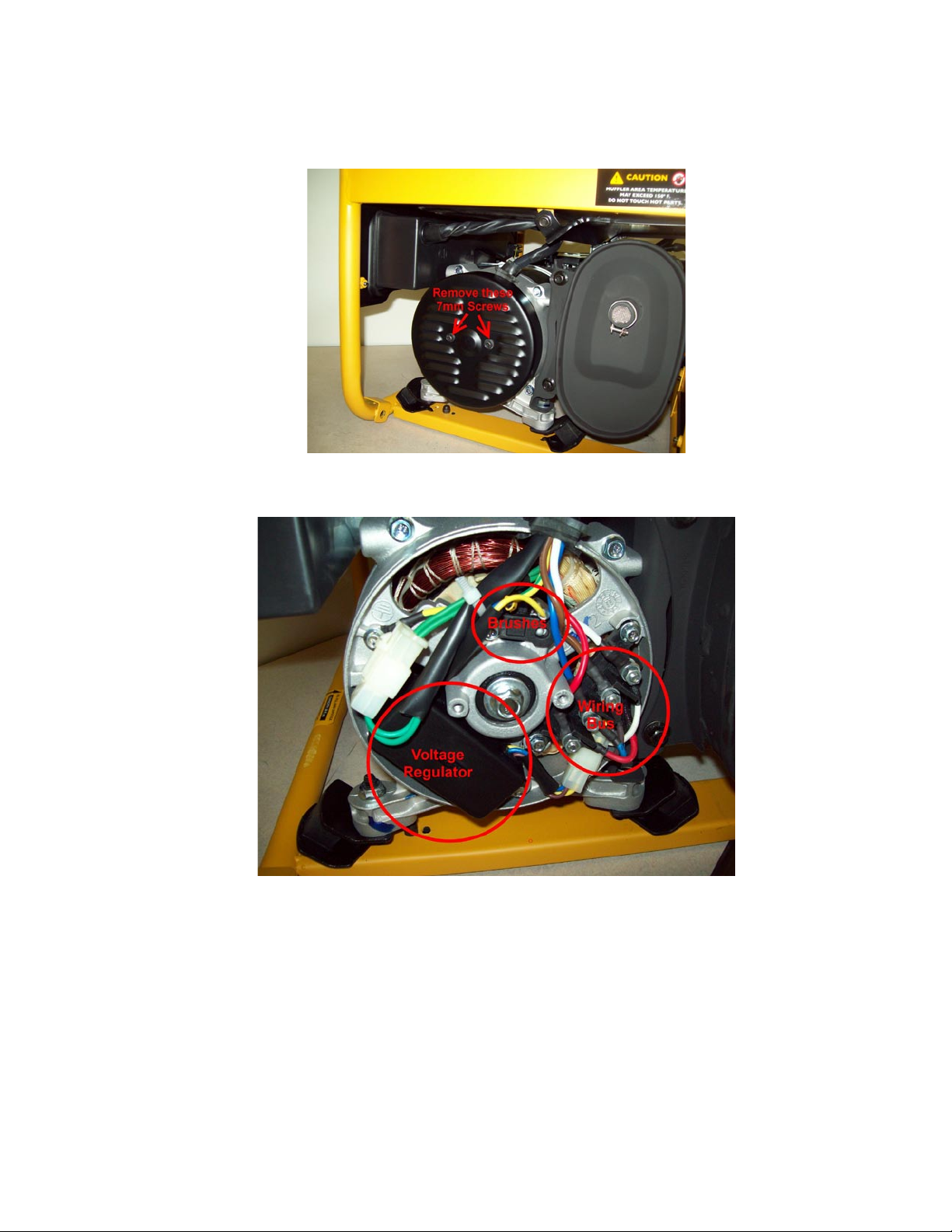
Locate the vented cover to the left of the Muffler and remove the two screws holding the cover
in place. The screws are either 7mm or 10mm, depending on the model.
Under the cover you will see the main components of the generator circuit. The Voltage
Regulator is a rectangular box held in place with two 7mm screws.
The Brush Assembly is at the top with two individual wires attached to it.
The Brush assembly is held in position with one 7mm screw.
The Wiring Bus connects the Stator to the Control Panel on the front.

Remove the Brush Assembly by loosening the 7mm screw.
Check the carbon on the Brushes for any broken ends or excessive wear. The brushes are
spring-loaded and should bounce back out when you push the brushes into the housing.
Brushes that are cracked, chipped or worn should be replaced. Brushes that stick in the
housing and do not spring back out should be replaced.
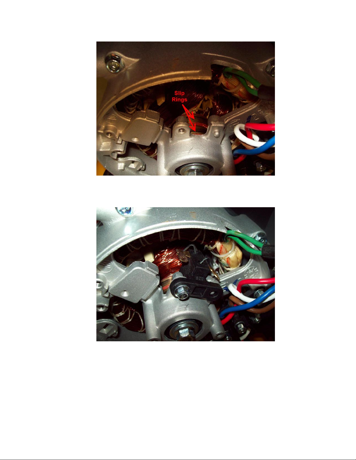
The Brushes make connection with the Rotor by riding on the Slip Rings. With the Brush
Assembly removed you should clean the slip rings of carbon build-up using rubbing alcohol
and a rag or, in severe cases, emery cloth.
Reinstall the Brush Assembly by aligning it with the index post on the Housing and tightening
the 7mm screw. It is normal for the Brush Assembly to be slightly tilted but the carbon should
make good contact on the Slip Rings.
With the Brush Assembly in place you can test the exciter voltage by starting the Generator
and reading the output to the brushes with a DC Voltmeter.
Typical exciter voltage readings are 10 to 12 Volts DC.

Attach the wires from the Voltage Regulator to the Brush Assembly.
Polarity is important. The Positive wire from the Voltage Regulator is marked with a “+”
symbol. It should be plugged into the tab on the left.
The unmarked lead is the Negative wire.
If the polarity is reversed, the Generator will not produce power.
Locate the Wiring Bus and test the Stator windings with an Ohm meter.
In this particular model there are TWO sets of Stator windings.
Consult the Wiring Diagram in the back of your Owner’s Manual for the color coding of the
windings.
Red and Blue are the colors of one set of windings here.
Brown and White make up the other set.
Disconnect the Voltage Regulator before making any test readings.

The Generator motor should NOT be running during these tests.
Each set should make a closed circuit when tested with an Ohm meter. You should get a
reading in the range of 50 to 150 Ohms from each set of windings. An open circuit indicates
that there is a break in the windings, meaning the stator is bad.
In addition, you should take Ohm readings from one set of windings to the other, and to
ground. These readings should be OPEN. If they are not open it means that the windings are
shorting out to the other coil or to ground, a condition that is usually due to the coils
overheating and melting the insulation. Check the COLOR of he coils on the rotor and stator
to see if any of them have turned blue or black. They should all be the same copper color.
Remove the Voltage Regulator by removing the 7mm screws on either end.
The Voltage Regulator is wired to the Brush Assembly on one end

…and a quick-disconnect terminal on the other.
As noted above, the Brush Assembly polarity is important. Make sure the Voltage Regulator
wires going to the Brushes are installed correctly. The wire marked with a “+” should be
attached to the tab on the LEFT.
Reattach the quick-disconnect terminal.
Before reinstalling the cover, dress the wires to prevent them from touching moving parts when
the Generator is running.

Position the Sealing Grommet before reinstalling the cover.
Reattach Cover and tighten the 7mm screws.
 Loading...