

Page 1
MODEL 3939, 3939T
9-INCH BENCHTOP
BAND SAW
Instruction Manual
NEED HELP? CONTACT US!
Have product questions? Need technical support? Please feel free to contact us:
TECHSUPPORT@WENPRODUCTS.COM1-800-232-1195 (M-F 8AM-5PM CST)
IMPORTANT: Your new tool has been engineered and manufactured to WEN’s highest standards for dependability,
ease of operation, and operator safety. When properly cared for, this product will supply you years of rugged,
trouble-free performance. Pay close attention to the rules for safe operation, warnings, and cautions. If you use
your tool properly and for its intended purpose, you will enjoy years of safe, reliable service.
For replacement parts and the most up-to-date instruction manuals, visit WENPRODUCTS.COM
Page 2

CONTENTS
WELCOME 3
Introduction ..................................................................................................... 3
Specifications ................................................................................................... 3
SAFETY 4
General Safety Rules ........................................................................................ 4
Specific Rules For Your Band Saw ................................................................... 6
Electrical Information ....................................................................................... 8
BEFORE OPERATING 9
Unpacking & Packing List .................................................................................9
Assembly & Adjustment ................................................................................. 10
OPERATION & MAINTENANCE 15
Operation ....................................................................................................... 15
Maintenance ................................................................................................... 17
Troubleshooting Guide ....................................................................................17
Exploded View & Parts List .............................................................................19
Warranty Statement ....................................................................................... 22
To purchase replacement blades for your band saw, visit WENPRODUCTS.COM
2
Page 3

INTRODUCTION
Thanks for purchasing the WEN Benchtop Band Saw. We know you are excited to put your tool to work, but first,
please take a moment to read through the manual. Safe operation of this tool requires that you read and understand
this operator’s manual and all the labels affixed to the tool. This manual provides information regarding potential
safety concerns, as well as helpful assembly and operating instructions for your tool.
SAFETY ALERT SYMBOL: Indicates danger, warning, or caution. The safety symbols and the explanations
with them deserve your careful attention and understanding. Always follow the safety precautions to reduce the
risk of fire, electric shock or personal injury. However, please note that these instructions and warnings are not
substitutes for proper accident prevention measures.
NOTE: The following safety information is not meant to cover all possible conditions and situations that may occur.
WEN reserves the right to change this product and specifications at any time without prior notice.
At WEN, we are continuously improving our products. If you find that your tool does not exactly match this manual,
please visit wenproducts.com for the most up-to-date manual or contact our customer service at 1-800-232-1195.
Keep this manual available to all users during the entire life of the tool and review it frequently to maximize
safety for both yourself and others.
SPECIFICATIONS
Model Number 3939T
Motor 120V, 60Hz, 300W, 2.8A
Throat 9 Inches
Cutting Depth 3-5/8 Inches
Blade Speed 2460 FPM
Blade Length 62 Inches
Blade Width 1/8 to 3/8 Inches
Work Table Bevel 0-45 Degrees
Work Table Dimensions 12 x 12 Inches
Weight 44 Pounds
3
Page 4

GENERAL SAFETY RULES
WARNING! Read all safety warnings and all instructions. Failure to follow the warnings and instructions may
result in electric shock, fire and/or serious injury.
Safety is a combination of common sense, staying alert and knowing how your item works. The term “power tool”
in the warnings refers to your mains-operated (corded) power tool or battery-operated (cordless) power tool.
SAVE THESE SAFETY INSTRUCTIONS.
WORK AREA SAFETY
1. Keep work area clean and well lit. Cluttered or dark
areas invite accidents.
2. Do not operate power tools in explosive atmospheres, such as in the presence of flammable liquids,
gases or dust. Power tools create sparks which may ig-
nite the dust or fumes.
3. Keep children and bystanders away while operating
a power tool. Distractions can cause you to lose control.
ELECTRICAL SAFETY
1. Power tool plugs must match the outlet. Never modify the plug in any way. Do not use any adapter plugs
with earthed (grounded) power tools. Unmodified plugs
and matching outlets will reduce risk of electric shock.
2. Avoid body contact with earthed or grounded surfaces such as pipes, radiators, ranges and refrigerators.
There is an increased risk of electric shock if your body
is earthed or grounded.
3. Do not expose power tools to rain or wet conditions.
Water entering a power tool will increase the risk of electric shock.
4. Do not abuse the cord. Never use the cord for carrying, pulling or unplugging the power tool. Keep cord
away from heat, oil, sharp edges or moving parts.
Damaged or entangled cords increase the risk of electric
shock.
5. When operating a power tool outdoors, use an extension cord suitable for outdoor use. Use of a cord
suitable for outdoor use reduces the risk of electric
shock.
6. If operating a power tool in a damp location is unavoidable, use a ground fault circuit interrupter (GFCI)
protected supply. Use of a GFCI reduces the risk of elec-
tric shock.
PERSONAL SAFETY
1. Stay alert, watch what you are doing and use common sense when operating a power tool. Do not use a
power tool while you are tired or under the influence
of drugs, alcohol or medication. A moment of inatten-
tion while operating power tools may result in serious
personal injury.
2. Use personal protective equipment. Always wear
eye protection. Protective equipment such as a respira-
tory mask, non-skid safety shoes and hearing protection
used for appropriate conditions will reduce the risk of
personal injury.
3. Prevent unintentional starting. Ensure the switch is
in the off-position before connecting to power source
and/or battery pack, picking up or carrying the tool.
Carrying power tools with your finger on the switch or
energizing power tools that have the switch on invites
accidents.
4. Remove any adjusting key or wrench before turning
the power tool on. A wrench or a key left attached to a
rotating part of the power tool may result in personal
injury.
5. Do not overreach. Keep proper footing and balance
at all times. This enables better control of the power
tool in unexpected situations.
6. Dress properly. Do not wear loose clothing or jewelry. Keep your hair and clothing away from moving
parts. Loose clothes, jewelry or long hair can be caught
in moving parts.
4
Page 5

GENERAL SAFETY RULES
WARNING! Read all safety warnings and all instructions. Failure to follow the warnings and instructions may
result in electric shock, fire and/or serious injury.
Safety is a combination of common sense, staying alert and knowing how your item works. The term “power tool”
in the warnings refers to your mains-operated (corded) power tool or battery-operated (cordless) power tool.
SAVE THESE SAFETY INSTRUCTIONS.
7. If devices are provided for the connection of dust
extraction and collection facilities, ensure these are
connected and properly used. Use of dust collection
can reduce dust-related hazards.
POWER TOOL USE AND CARE
1. Do not force the power tool. Use the correct power
tool for your application. The correct power tool will
do the job better and safer at the rate for which it was
designed.
2. Do not use the power tool if the switch does not turn
it on and off. Any power tool that cannot be controlled
with the switch is dangerous and must be repaired.
3. Disconnect the plug from the power source and/or
the battery pack from the power tool before making
any adjustments, changing accessories, or storing
power tools. Such preventive safety measures reduce
the risk of starting the power tool accidentally.
4. Store idle power tools out of the reach of children
and do not allow persons unfamiliar with the power
tool or these instructions to operate the power tool.
Power tools are dangerous in the hands of untrained users.
5. Maintain power tools. Check for misalignment or
binding of moving parts, breakage of parts and any
other condition that may affect the power tool’s operation. If damaged, have the power tool repaired before
use. Many accidents are caused by poorly maintained
power tools.
6. Keep cutting tools sharp and clean. Properly maintained cutting tools with sharp cutting edges are less
likely to bind and are easier to control.
7. Use the power tool, accessories and tool bits, etc.
in accordance with these instructions, taking into account the working conditions and the work to be performed. Use of the power tool for operations different
from those intended could result in a hazardous situation.
8. Use clamps to secure your workpiece to a stable
surface. Holding a workpiece by hand or using your
body to support it may lead to loss of control.
9. KEEP GUARDS IN PLACE and in working order.
SERVICE
1. Have your power tool serviced by a qualified repair
person using only identical replacement parts. This
will ensure that the safety of the power tool is maintained.
CALIFORNIA PROPOSITION 65 WARNING
Some dust created by power sanding, sawing, grinding,
drilling, and other construction activities may contain
chemicals, including lead, known to the State of California to cause cancer, birth defects, or other reproductive
harm. Wash hands after handling. Some examples of
these chemicals are:
• Lead from lead-based paints.
• Crystalline silica from bricks, cement, and other
masonry products.
• Arsenic and chromium from chemically treated
lumber.
Your risk from these exposures varies depending on
how often you do this type of work. To reduce your exposure to these chemicals, work in a well-ventilated area
with approved safety equipment such as dust masks
specially designed to filter out microscopic particles.
5
Page 6

SPECIFIC RULES FOR YOUR BANDSAW
WARNING! Do not operate the power tool until you have read and understood the following instructions and
the warning labels.
SAW BLADE SAFETY
1. Always wear protective gloves when handling saw
blades.
2. Only use blades with correct size and type for both
your band saw and your workpiece.
3. Never use damaged or deformed saw blades. Only use
sharp blades.
4. Install the saw blade in the correct orientation indi-
cated in the instructions.
5. Keep hands out of path of saw blade. Never use your
hands to remove sawdust or scrap wood. Use a brush at
all times.
6. Never reach around saw blade or reach in back of the
saw blade.
7. The use of accessories or attachments not recommended by the manufacturer may result in a risk of personal injury.
PERSONAL SAFETY
1. Operate in a well ventilated area. Keep the floor area
around the band saw level and free of slippery substances or other tripping hazards.
6. Always turn off and unplug the band saw before making any adjustments or repair tasks. Never adjust the
band saw or the workpiece while the saw is running.
7. Only use the band saw to cut wood.
PREPARING THE BAND SAW
When transporting the band saw, use the transportation handle and roll the assembled saw with the wheels.
Never carry the device by its guards or its accessories.
1. Examine the band saw for any damaged or missing
parts. Replace or repair damaged parts before operation.
Periodically check that all nuts, bolts and other fasteners
are properly tightened.
SECURE YOUR WORKPIECE
1. To avoid blade binding or loss of control, always secure the workpiece to a stable platform, ensuring that
body exposure is minimized. Use clamps to secure the
workpiece. Never perform any operation freehand.
2. Ensure that work is correctly supported. Supports
must be placed under the workpiece on both sides, close
to the line of cut and near the edge of the workpiece.
3. For accuracy of cut, and to avoid blade binding, always use a rip fence or straight edge guide.
2. Wear ANSI-approved safety goggles to protect your
eyes from saw dust. Use hearing protection to protect
yourself from hearing loss.
3. People with pacemakers should consult their
physician(s) before use. Electromagnetic fields in close
proximity to pacemakers could cause pacemaker interference or pacemaker failure.
4. Wear work gloves when handling saw blades. DO NOT
wear gloves, neckties, jewelry, or loose clothing while
operating the saw.
5. Saw dust is harmful to your health. Use NIOSH-approved dust masks or other respiratory protection during operation and cleaning.
6
4. Never hand-hold a workpiece that is too small to be
clamped, as it can be launched away and cause injury.
Use proper support and guides to secure the small workpiece.
5. Use extra caution with very large, very small, or awkwardly-shaped workpieces. Small pieces should be secured with clamps. Do not hold small pieces with your
hand because your fingers might go under the blade
guard.
6. Support round work properly (use a V block or press
it against the miter gauge) to prevent it from rolling and
the blade from biting.
Page 7

SPECIFIC RULES FOR YOUR BANDSAW
WARNING! Do not operate the power tool until you have read and understood the following instructions and
the warning labels.
7. Plan intricate or small work carefully to avoid pinching
the blade. Avoid awkward operations and hand positions
to prevent accidental contact with the blade.
DURING CUTTING OPERATIONS
1. Always stand to one side when operating the saw.
Never have any part of the body in line with the path of
the saw. Never hold a workpiece in your hand or across
your legs while cutting.
2. Ensure hands are away from the cutting area and
blade. Keep one hand on the rear handle, and the other
on the front grip. If both hands are holding the tool they
cannot be cut by the blade.
3. Feed work into the blade against the direction of rotation of the blade only.
4. If you are interrupted when operating the saw, complete the process and switch the saw off before looking
up.
9. Never cut more than one piece at a time. Do not stack
workpieces together. Do not attempt to cut material
thicker than specified in this manual. Adjust the cutting
depth to the thickness of the workpiece.
10. If a cut does not extend to the edge of the workpiece,
or if the blade binds in the cut, allow the blade to come
to a complete stop and lift the saw out of the workpiece.
11. Turn off tool and wait for saw blade to stop before
moving workpiece or changing settings. Do not slow
or stop a blade with a piece of wood or by hand. Let
the blade come to rest naturally. Do not attempt to free
a jammed blade while the machine is still running and
connected to power.
12. Always raise the blade to be covered by the blade
guard after use.
5. Power tools must always be held by the insulated
gripping surfaces when performing an operation, ensuring protection if the cutting tool makes contact with its
own cord or hidden wiring. Contact with a ‘live’ wire will
make exposed metal parts of the power tool ‘live’ and
shock the operator if the insulated gripping surfaces are
not used.
6. Do not use the band saw unless all guards are in
place. Do not operate with any guard disabled, damaged,
or removed. Moving guards must move freely and close
instantly.
7. Blade guide, supports, bearings, and blade tension
must be properly adjusted to avoid accidental blade contact and to minimize blade breakage. To maximize blade
support, always adjust the upper blade guide and blade
guard so that it barely clears the workpiece.
8. Turn on the band saw and let it reach full speed, then
slowly slide the saw into the workpiece. This will help
produce safer and cleaner cuts.
7
Page 8
ELECTRICAL INFORMATION
GROUNDING INSTRUCTIONS
In the event of a malfunction or breakdown
current and reduces the risk of electric shock. This tool is equipped with an electric cord that has an
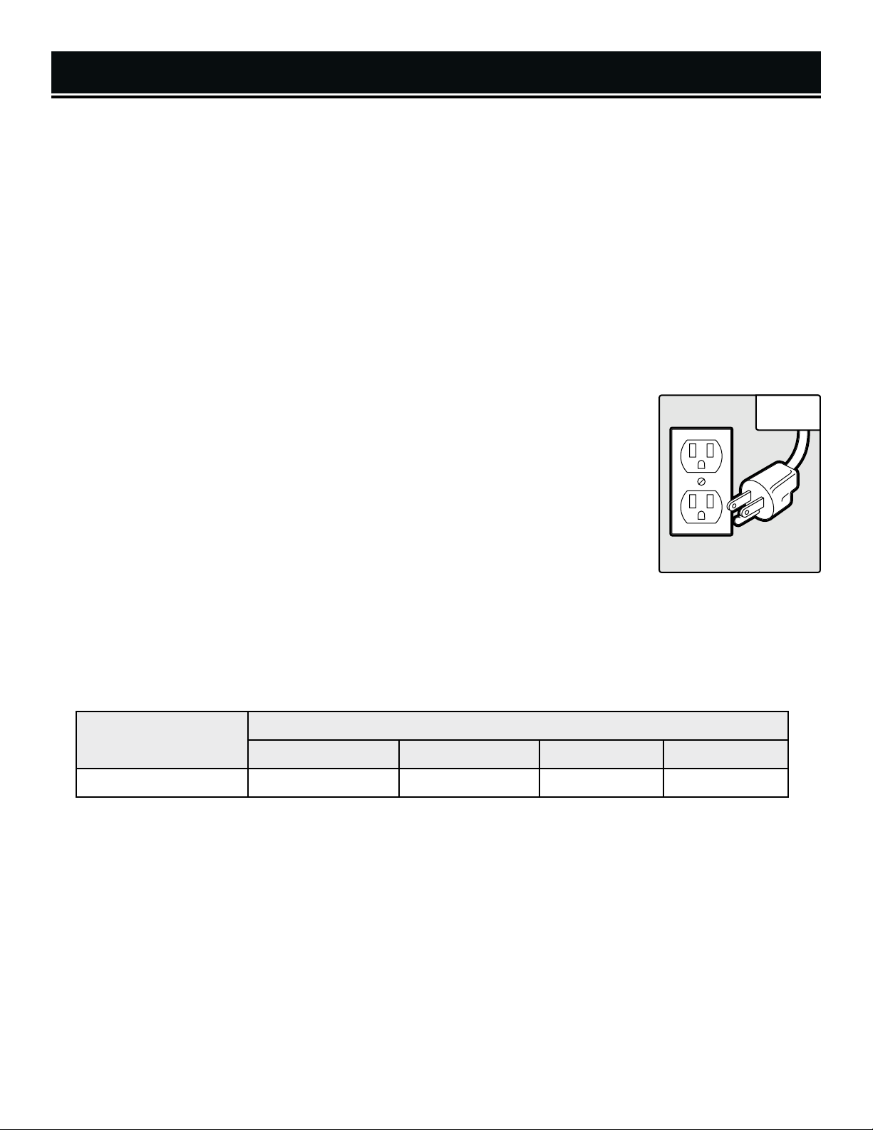
equipment grounding conductor and a grounding plug. The plug MUST be plugged into a matching outlet
that is properly installed and grounded in accordance with ALL local codes and ordinances.
, grounding provides the path of least resistance for an electric
1. Do not modify the plug provided.
electrician.
2. Improper connection
with the green insulation (with or without yellow stripes) is the equipment grounding conductor. If repair or
replacement of the electric cord or plug is necessary, DO NOT connect the equipment grounding conductor
to a live terminal.
3. Check
understand the grounding instructions or whether the tool is properly grounded.
4. Use only three-wire extension cords
that accept the tool’s plug (INSERT CR). Repair or replace a damaged or worn cord
immediately.
CAUTION!
you are not sure, have a licensed electrician check the outlet.
with a licensed electrician or service personnel if you do not completely
In all cases, make certain the outlet in question is properly grounded. If
of the equipment grounding conductor can result in electric shock. The conductor
If it will not fit the outlet, have the proper outlet installed by a licensed
Fig. 1
that have three-pronged plugs and outlets
GUIDELINES AND RECOMMENDATIONS FOR EXTENSION CORDS
When using an extension cord, be sure to use one heavy enough to carry the current your product will draw. An undersized cord will cause a drop in line voltage resulting in loss of power and overheating. The table below shows the
correct size to be used according to cord length and ampere rating. When in doubt, use a heavier cord. The smaller
the gauge number, the heavier the cord.
AMPERAGE
25 ft. 50 ft. 100 ft. 150 ft.
2.8A 18 gauge 16 gauge 16 gauge 14 gauge
1. Examine extension cord before use. Make sure your extension cord is properly wired and in good condition.
Always replace a damaged extension cord or have it repaired by a qualified person before using it.
2. Do not abuse extension cord. Do not pull on cord to disconnect from receptacle; always disconnect by pulling on
plug. Disconnect the extension cord from the receptacle before disconnecting the product from the extension cord.
Protect your extension cords from sharp objects, excessive heat and damp/wet areas.
3. Use a separate electrical circuit for your tool. This circuit must not be less than a 12-gauge wire and should be
protected with a 15A time-delayed fuse. Before connecting the motor to the power line, make sure the switch is in
the OFF position and the electric current is rated the same as the current stamped on the motor nameplate. Running
at a lower voltage will damage the motor.
8
REQUIRED GAUGE FOR EXTENSION CORDS
Page 9

UNPACKING & PACKING LIST
UNPACKING
With the help of a friend or trustworthy foe, such as one of your in-laws, carefully remove the band saw from the
packaging and place it on a sturdy, flat surface. Make sure to take out all contents and accessories. Do not discard
the packaging until everything is removed. Check the packing list below to make sure you have all of the parts and
accessories. If any part is missing or broken, please contact customer service at 1-800-232-1195 (M-F 8-5 CST),
or email techsupport@wenproducts.com.
2
3
1
1. Band Saw ...............................................................1
2. Fence .....................................................................1
3. Table Assembly ......................................................1
4. Open Spanner ........................................................1
5
4
5. 6mm Hex Wrench ..................................................1
6. 4mm Hex Wrench ..................................................1
7. Miter Gauge ...........................................................1
8. Feet ........................................................................4
6
7
8
ASSEMBLY & ADJUSTMENT TOOLS
The tools listed below are not included but are required for either assembly or adjustment:
• 13mm Open-End Wrenches (2)
• Phillips-Head Screwdriver (1)
• Combination Square (1)
9
Page 10

ASSEMBLY & ADJUSTMENTS
ASSEMBLING YOUR BAND SAW
1. Attach the four feet to the base of the band saw (Fig. 2).
2. Remove the D-nut (Fig. 3 - 1), washer (Fig. 3 - 2), and wing screw (Fig.
3 - 3) from the saw’s table assembly (Fig. 3).
3. Remove the bevel locking handle (Fig. 5 - 1) and washer (Fig. 5 - 2)
Slide the table onto the band saw, making sure the blade stays within the
table slot (Fig. 4). Pull back on the angle adjustment knob (Fig. 5 - 3) and
align the teeth on the table bracket with the teeth on the angle adjustment
knob. Release the knob.
4. Re-install the bevel locking handle and washer (Fig. 5).
NOTE: The locking handle is spring-loaded and can be re-positioned. To
re-position the handle, pull the handle body outwards, turn it to the desired position, then let it spring back in.
5. Mount the saw to a workbench or other sturdy surface using the three
holes provided on the base (Fig. 6 - 1). Mounting hardware is not included with the saw. Use M8 or 1/4” fasteners.
Fig. 2
1
2
3
Fig. 3
Fig. 4
6. Place the miter gauge into the miter gauge slot (Fig. 6 - 2).
7. Pull up on the fence locking lever (Fig. 6 - 3) to release it. Place the
fence on the table, ensuring it is parallel to the blade. Push down on the
fence locking lever to lock the fence to the table.
Fig. 5 Fig. 6
1
3
2
3
2
1
10
Page 11

ASSEMBLY & ADJUSTMENTS
BEVELING THE TABLE
1. Loosen the locking handle (Fig. 7 – 1). Adjust the table to the
desired position using the table bevel knob (Fig. 7 – 2).
2. Use the angle indicator to confirm the desired angle, then tighten
the locking handle.
NOTE: The locking handle is spring-loaded and can be re-positioned. To re-position the handle, pull the handle body outwards,
turn it to the desired position, then let it spring back in.
1
2
Fig. 7
SETTING THE 0° POSITIVE STOP
The 0° positive stop screw can be adjusted as described below.
1. Loosen the nut on the positive stop screw. Use a wrench to grip
the screw’s hex head, and turn it to adjust it upwards or downwards.
2. Use a bubble level to check that the table is level, and a combination square to ensure that the table is square to
the blade. Make adjustments to the positive stop as necessary, then tighten the nut.
3. Examine the angle pointer on the bevel guide bracket, and ensure it points to 0°. If it does not, use a Phillips-head
screwdriver (not included) to loosen the screw on the pointer. Adjust the pointer so it points to 0°. Tighten the screw.
ADJUSTING THE BLADE TRACKING
Blade tracking refers to the adjustments that are made in order to keep the blade riding on the wheels smoothly and
evenly. Blade tracking has been set by the factory. However, when you install a new blade, you may need to adjust
the tracking settings. Follow the directions below.
WARNING! Blade teeth are sharp! Use care, ANSI Z87.1-approved eye protection, long sleeves, and protec-
tive gloves when handling the saw blade. Failure to comply may cause serious injury.
1. Turn off and unplug the band saw. Wait for it to come to a complete stop before opening any covers.
2. Open the upper and lower doors (Fig. 8).
3. Use one hand to grip the spokes of the upper wheel and turn it clockwise (as viewed from the front of the saw),
observing the blade tracking. Do not touch the blade.
4. SLOWLY turn the tracking knob (Fig. 9 - 2) while rotating the upper wheel. Turning the tracking knob clockwise
(as viewed from the back of the saw) will cause the blade to track more towards the rear of the saw; turning it counterclockwise will cause the blade to track more towards the front of the saw.
NOTE: You may only need to adjust the tracking knob by 1/4 turn or so. Make only small adjustments – this will
make tracking the blade properly much easier.
5. The blade tracking is properly set when the tooth gullets (the valleys between the blade teeth) ride along the center of the tire. Tighten the tracking lock knob, and close the covers.
11
Page 12

ASSEMBLY & ADJUSTMENTS
ADJUSTING BLADE TENSION
WARNING! If the blade tension is too high, the blade may
break. If the tension is too low, the blade may slip, stall, or
wander during a cut.
WARNING! Blade teeth are sharp! Use care, ANSI Z87.1-
approved eye protection, long sleeves, and protective gloves
when handling the saw blade. Failure to comply may cause
serious injury.
1. Raise the upper blade guide (see “RAISING AND LOWERING
THE UPPER BLADE GUIDE”).
2. Open the upper door.
3. With a gloved finger, gently press the blade sideways. Take this
measurement at the left side of the saw, before the blade touches
the upper wheel. When tension is properly adjusted, the blade
should not move more than 1/8-inch.
Fig. 8
Fig. 9
1
4. Use the blade tension knob (Fig. 9 - 1) to make fine adjustments to the blade tension. Turning the knob clockwise will increase blade tension; turning it counterclockwise will decrease
blade tension.
RAISING AND LOWERING THE UPPER BLADE GUIDE
The height of the upper blade guard should be adjusted prior to
every cut. The blade guide should always be positioned as close
to the upper face of the workpiece as possible – no more than 1/8
inch (3mm).
1. Loosen the adjustment locking knob (Fig. 10 - 1) on the rear of
the saw. Use the adjustment knob (Fig. 10 - 2) to adjust the height
of the upper blade guide. Tighten the adjustment locking knob
once the desired setting has been reached.
2
Fig. 10
1
2
12
Page 13

ASSEMBLY & ADJUSTMENTS
ADJUSTING THE UPPER GUIDE BEARINGS
Proper adjustment of the guide bearings is one of the best things
you can do for your saw – it will prolong blade life, prolong bearing life, and help prevent blade “drift”. Turn off and unplug the
band saw before beginning. Open the upper door.
WARNING! The upper blade guide bearings must be ad-
justed after every blade change and tracking adjustment.
1. Use a hex wrench to loosen the lower set screw (Fig. 11 - 1) on
the right side of the upper guide bearing assembly. Position the
assembly so that the roller bearings are about 1 – 2 mm (1/10
inch) behind the tooth gullets. Tighten the screw.
NOTE: Ensure that you do not rotate the upper guide bearing assembly about the shaft. Make sure the screw is tightened onto the
flat of the shaft.
2. Use a hex wrench to loosen the upper set screw (Fig. 11 – 2)
on the right side of the assembly. Position the thrust bearing so
that it is as close to the spine of the blade as possible, without
touching it.
Fig. 11
2
1
Fig. 12
3. Rotate the blade a few times to ensure that the spine of the
blade does not touch the bearing at all while the blade is rotating.
Once the bearing has been properly positioned, tighten the screw.
4. Use a hex wrench to loosen the socket-head cap screws on the
front of the assembly (Fig. 12). Position the roller bearings, left
and right, so that they are as close as possible to the body of the
blade without touching it. This will be about 0.5mm (1/50 inch).
5. Rotate the blade a few times to ensure that the body of the blade does not touch either roller bearing at all while
the blade is rotating. Once the bearings have been properly positioned, tighten the screws.
ADJUSTING THE LOWER GUIDE BEARINGS
Proper adjustment of the guide bearings is one of the best things you can do for your saw – it will prolong blade
life, prolong bearing life, and help prevent blade “drift”. Turn off and unplug the band saw before beginning. Open
the lower door.
WARNING! The lower blade guide bearings must be adjusted after every blade change and tracking adjust-
ment.
TIP: Insert the hex wrenches through the holes in the right side of the housing in order to access the screws more
easily.
1. Use a hex wrench to loosen the upper socket-head cap screw (Fig. 13 – 1). Position the assembly so that the roller
bearings are about 1 – 2 mm (1/10 inch) behind the tooth gullets. Tighten the screw.
13
Page 14

ASSEMBLY & ADJUSTMENTS
2. Use a hex wrench to loosen the lower socket-head cap screw
(Fig. 13 – 2). Position the thrust bearing so that it is as close to
the spine of the blade as possible, without touching it.
3. Rotate the blade a few times to ensure that the spine of the
blade does not touch the bearing at all while the blade is rotating.
Once the bearing has been properly positioned, tighten the screw.
4. Use a hex wrench to loosen the socket-head cap screws on the
front of the assembly (Fig. 13 – 1 & 2). Position the roller bearings, left and right, so that they are as close as possible to the
body of the blade without touching it. This will be about 0.5mm
(1/50 inch).
5. Rotate the blade a few times to ensure that the body of the blade does not touch either roller bearing at all while
the blade is rotating. Once the bearings have been properly positioned, tighten the screws.
1
2
Fig. 13
ADJUSTING THE BELT TENSION
Use the instructions below to adjust the belt tension, as needed, over the life of your saw. Older belts may stretch
with use. If you do not plan to use the saw for longer than 1 week, release the tension on the drive belt in order to
prolong its life.
WARNING! Disconnect machine from the power source! Never make adjustments with the machine run-
ning. Failure to comply may cause serious injury.
1. Open the lower cover. Be careful to not touch the blade.
2. Loosen the socket-head cap screw on the back of the motor-mounting flange, then move the motor towards the
center of the saw to lower tension on the belt. Move the motor towards the outside of the saw to increase tension
on the belt.
3. Tighten the screw once the desired belt tension has been achieved. The belt is properly tensioned when firm
downward pressure on the belt, applied with a finger on the bottom of the belt between the pulleys (may need line
art), moves the belt no more than 1/8” (3mm).
14
Page 15

OPERATION
SWITCH BOX
Use the power switch (Fig. 14 – 1) to turn the saw ON or OFF.
Remove the yellow safety key when the saw is OFF to prevent
unauthorized use. Store the safety key in a safe place out of the
reach of children.
GENERAL CUTTING GUIDELINES
WARNING! Operating a band saw involves a certain
amount of risk. Read the instructions and plan your work before cutting a workpiece.
1. Make a test cut on scrap wood to test the settings and get the
hang of operating the band saw.
2. Make all adjustments with the band saw turned OFF and unplugged.
3. Make sure the upper guard is close to the upper face of your
workpiece (see “RAISING AND LOWERING THE UPPER BLADE
GUIDE”).
Fig. 14
1
Fig. 15
1
4. Always use the push stick when cutting intricate or narrow
workpieces. Keep fingers, hands, and other beloved body parts
away from the blade!
5. Do not force the workpiece against the blade. Let the tool do
the work. Light contact gives easier cutting and prevents excess
friction, which will prolong the life of the blade and prevents workpiece burning.
6. Always use dust collection. A 2” dust port (Fig. 15 - 1) is located on the back of the saw, next to the motor (see
“KNOW YOUR BANDSAW”). Use a hose clamp (if necessary) to secure the adapter or dust hose to the dust port.
7. The band saw is most suitable for straight-line cutting (cross-cutting, ripping, miter cutting, beveling, compound
cutting, and resawing). While it can certainly cut curves, it is not a scroll saw, and cannot perform the same kinds
of cuts. Do not cut sharp corners; instead, saw around corners.
CUTTING CURVES
When freehand-cutting curves, carefully turn the workpiece so that the blade follows the cut line without twisting. If
the curve is so sharp that you repeatedly back up and cut new kerf, use a narrower blade, or a blade with more set
(that is, the teeth are further apart). When a blade has more set, the workpiece turns more easily, but you will get a
rougher cut.
When changing a cut, do not withdraw the workpiece from the blade – the workpiece may drag the blade off the
wheels. Instead, turn the workpiece and cut out through the scrap section of the workpiece. When cutting long
curves, make relief cuts as you go along.
15
Page 16

OPERATION
USING THE MITER GAUGE
1. Place the miter gauge into the slot on the table.
2. Loosen the knob on the gauge and set a new miter angle (between 0° and 60°).
3. Tighten the knob.
CHANGING BLADES
WARNING! Always be sure that the band saw is turned
OFF and unplugged before making any adjustments.
WARNING! Blade teeth are sharp! Use care, ANSI Z87.1-approved eye protection, long sleeves, and protec-
tive gloves when handling the saw blade. Failure to comply may cause serious injury.
1. Double-check that the band saw is turned OFF and disconnected from the power source.
2. Open the upper and lower doors.
3. Turn the blade tension knob (Fig. 9 - 1) to relieve tension on the blade.
Fig. 16
4. Remove the blade from the wheels and from between the upper and lower bearing guides. Guide it through the
table slot. Store the blade in a safe place.
5. Guide the new blade through the table slot, spine first. The blade teeth should be facing you, pointing down towards the table.
6. Place the blade on the upper and lower wheels, and between the bearing guides (Fig. 12).
7. Place the blade under proper tension (see “ADJUSTING BLADE TENSION”).
8. Adjust the blade tracking (see “ADJUSTING THE BLADE TRACKING”).
9. Adjust the upper and lower bearing guides (see sections on page 13).
10. Make a test cut on a scrap piece of wood before resuming cutting.
16
Page 17

MAINTENANCE
WARNING! Always turn OFF and unplug the band saw before performing any maintenance.
1. Always use a dust collection system. This will help prevent sawdust from building up inside the band saw.
2. Wipe off the table after every use. Remove any pitch, sap, or resin that has accumulated on the table, blade guide,
bearings, etc. using a damp cloth.
3. At least once a month, open the doors and vacuum out any accumulated dust, shavings, etc. Remove the blade
and clean off any built-up sawdust from the wheels and tires using a stiff brush.
4. Check the drive belt at least monthly for proper tension and any signs of wear.
5. As needed, apply a light coat of good-quality paste wax to the table. This will help provide a smooth gliding surface for your workpieces.
6. The bearings on your band saw are permanently sealed and lubricated, and require no additional lubrication.
7. If you do not plan to use the saw for a long period of time (over 1 week), release tension on the blade, as well as
on the drive belt. This will help prolong blade life and belt life. Do not forget to re-engage the belt and blade tension
before using the saw again.
TROUBLESHOOTING GUIDE
WARNING! Stop using the generator immediately if any of the following problems occur or risk serious
personal injury. If you have any questions, please contact customer service at 1-800-232-1195 (M-F 8-5 CST),
or email techsupport@wenproducts.com.
Problem Possible Cause Solution
Check the saw and stand and ensure that all fasteners are tightened.
Adjust guide bearings properly (see sections on p.
13).
Adjust tracking properly (see "ADJUSTING THE
BLADE TRACKING").
Open up the saw doors and check to see if the blade
is hitting something (rotate wheels by hand).
Replace belt. Contact customer service (1-800-232-
1195) for assistance.
Remove blade. Rotate each wheel by hand, then
move the belt. Contact customer service (1-800-232-
1195) for assistance.
Saw is noisy.
Loose fastener.
Guide bearings improperly
adjusted.
Improper blade tracking
setting.
Blade is hitting something it
shouldn't.
Foreign object inside saw. Remove object.
Worn belt.
Worn wheel or motor bearing.
17
Page 18

TROUBLESHOOTING GUIDE
WARNING! Stop using the generator immediately if any of the following problems occur or risk serious
personal injury. If you have any questions, please contact customer service at 1-800-232-1195 (M-F 8-5 CST),
or email techsupport@wenproducts.com.
Problem Possible Cause Solution
Saw not plugged in. Plug in saw.
Band saw will not start
(no sound whatsoever).
Band saw will not start
(humming sound).
Power switch turned OFF, or
safety key not inserted.
Improper size/length of extension cord.
Bad outlet.
Defective power switch.
Blade overtightened.
Belt overtightened.
Bad start capacitor.
Bad motor bearing, or bad
motor.
Blade is improperly tensioned.
Insert safety key and turn saw ON.
Use proper extension cord. Refer to chart on p. 6.
Try another outlet, or have a qualified electrician check/
replace outlet.
Contact customer service (1-800-232-1195) for assistance.
Adjust blade tension properly (see "ADJUSTING BLADE
TENSION").
Adjust belt tension properly (see "ADJUSTING THE
CUTTING SPEED").
Contact customer service (1-800-232-1195) for assistance.
Contact customer service (1-800-232-1195) for assistance.
Adjust blade tension properly (see "ADJUSTING
BLADE TENSION").
18
Blade will not track
properly.
Blade "drifts".
Tracking knob is overadjusted.
Adjust tracking properly (see "ADJUSTING THE
BLADE TRACKING").
Blade is warped. Replace the blade.
Tires are worn.
Blade is improperly tensioned.
Contact customer service (1-800-232-1195) for assistance.
Adjust blade tension properly (see "ADJUSTING
BLADE TENSION").
Blade is dull. Replace blade.
Upper blade guard height
improperly set.
Guide bearings improperly
adjusted.
Improper blade tracking
setting.
Adjust upper blade guide height properly (see "RAISING AND LOWERING THE UPPER BLADE GUIDE").
Adjust guide bearings properly (see sections on p.
13).
Adjust tracking properly (see "ADJUSTING THE
BLADE TRACKING").
Improper feed rate. Do not force the workpiece. Let the tool do the work.
Blade is warped.
Contact customer service (1-800-232-1195) for assistance.
Page 19

EXPLODED VIEW & PARTS LIST
19
Page 20

EXPLODED VIEW & PARTS LIST
No. Part Description Qty.
1 3939-001 Blade Tension Knob 1
2 3939-002 Flat Washer 1
3 3939-003 Blade Tension Spring 1
4 3939-004 Carriage Bolt 1
5 3939-005 Pulling Plate 1
6 3939-006 Socket Head Screw 1
7 3939-007 Shaft 1
8 3939-008 Lock Catch 2
9 3939-009 Hex Nut 1
10 3939-010 Lock Washer 1
11 3939-011 Bevel Support Plate 1
12 3939-012 Upper Wheel Shaft 1
13 3939-013 Ball Bearing (6000ZZ) 4
14 3939-014 Upper Wheel 1
15 3939-015 Int. Retaining Ring 4
16 3939-016 Ext. Retaining Ring 2
17 3939-017 Tire 2
18 3939-018 Upper Wheel Cover 1
19 3939-019 Blade 1
20 3939-020 Lower Wheel Cover 1
21 3939-021 Lock Nut 2
22 3939-022 Bushing 2
23 3939-023 Socket Head Screw 2
24 3939-024 Lower Wheel 1
25 3939-025 Thread Forming Screw 3
26 3939-026 Drive Pulley 1
27 3939-027 Lower Wheel Shaft 1
28 3939-028 Hex Nut 4
29 3939-029 Hex Bolt 4
30 3939-030 Lock Nut 1
31 3939-031 Lifting Handle 1
32 3939-032 Pan Head Screw 2
33 3939-033 Frame 1
34 3939-034 Switch Box 1
35 3939-035 Pan Head Screw 2
36 3939-036 Switch Mounting Plate 1
37 3939-037 Thread Forming Screw 1
38 3939-038 Switch 1
39 3939-039 Lock Washer 2
40 3939-040 Serrated Washer 2
41 3939-041 Pan Head Screw 2
No. Part Description Qty.
42 3939-042 Hex Nut 1
43 3939-043 Flat Washer 2
44 3939-044 Bushing 1
45 3939-045 Brush 1
46 3939-046 Carriage Blot 1
47 3939-047 Foot 4
48 3939-048 Belt 1
49 3939-049 Dust Port 1
50 3939-050 Pan Head Screw 3
51 3939-051 Lock Nut 2
52 3939-052 Catching Knob 2
53 3939-053 Socket Head Screw 2
54 3939-054 Socket Head Screw 2
55 3939-055 Ball Bearing (606ZZ) 2
56 3939-056 Flat Washer 2
57 3939-057 Support Rod 1
58 3939-058 Socket Head Screw 4
59 3939-059 Ball Bearing (605ZZ) 4
60 3939-060 Flat Washer 4
61 3939-061 Lower Guide Block 1
62 3939-062 Square Nut 4
63 3939-063 Support Block 1
64 3939-064 Socket Head Screw 2
65 3939-065 Flat Washer 2
66 3939-066 Socket Head Screw 2
67 3939-067 Lower Protecting Cover 1
68 3939-068 Flat Washer 2
69 3939-069 Pan Head Screw 2
70 3939-070 Strain Relief 2
71 3939-071 Guide Plate 1
72 3939-072 Set Screw 1
73 3939-073 Pinion 1
74 3939-074 Adjustment Knob Seat 1
75 3939-075 Flat Washer 1
76 3939-076 Socket Head Screw 2
77 3939-077 Adjustment Knob 1
78 3939-078 Upper Guide Block 1
79 3939-079 Support Rod 1
80 3939-080 Flat Washer 2
81 3939-081 Socket Head Screw 1
82 3939-082 Socket Head Screw 1
20
Page 21

EXPLODED VIEW & PARTS LIST
No. Part Description Qty.
83 3939-083 Flat Washer 2
84 3939-084 Socket Head Screw 2
85 3939-085 Upper Cover Assembly 1
86 3939-086 Square Nut 1
87 3939-087 Guide Block 1
88 3939-088 Flat Washer 2
89 3939-089 Socket Head Screw 2
90 3939-090 Flat Washer 8mm 1
91 3939-091 Locking Knob 1
92 3939-092 Flat Washer 8mm 2
93 3939-093 Spring 1
94 3939-094 Tracking Knob 1
104 3939-104 Miter Gauge Assembly 1
105 3939-105 Table Insert 1
106 3939-106 Table 1
107 3939-107 D Nut 1
108 3939-108 Flat Washer 1
109 3939-109 Wing Screw 1
110 3939-110 Hex Nut 1
111 3939-111 Hex Bolt 1
112 3939-112 Bevel Case 1
113 3939-113 Flat Washer 4
No. Part Description Qty.
114 3939-114 Socket Head Screw 4
115 3939-115 Guide Bushing 2
116 3939-116 Socket Head Screw 2
117 3939-117 Flat Washer 1
118 3939-118 Locking Handle 1
119 3939-119 Pointer 1
120 3939-120 Flat Washer 1
121 3939-121 Pan Head Screw 1
122 3939-122 Table Adjusting Handle 1
123 3939-123 Spring 1
124 3939-124 Bolt 1
125 3939-125 Motor 1
126 3939-126 Sponge Ring 1
127 3939-127 Motor Pully 1
128 3939-128 Flat Washer 1
129 3939-129 Socket Head Screw 1
130 3939-130 Flat Washer 8mm 2
131 3939-131 Socket Head Screw 2
132 3939-132 Power Cord 1
133 3939-133 Fence Assembly 1
134 3939-134 Open Spanner 1
135 3939-135 Hex Wrench 2
21
Page 22

WARRANTY STATEMENT
WEN Products is committed to building tools that are dependable for years. Our warranties are consistent with this
commitment and our dedication to qualit
GRE
consumer
power tools will be free from defects in material or workmanship during personal use for a period of two (2) years
used
damaged parts.
SELLER’S
mitted
re
defective
misrepai
improper maintenance, or other conditions adversely affecting the
Product
make
clearly
dor
sales,
product.
Contact techsupport@wenproducts.com or 1-800-232-1195 with the following information to make arrangements:
your
or
defective parts and products may need to be sent to WEN before the replacements can be shipped out.
turning
must
be
product
the
will be returned and shipped back to the pur
THIS
INCLUDING
DUR
PROVINCES
TAT
IN
BUT
SOME ST
ION
OF
TO YOU.
THIS
WHICH
TO COUNT
THIS
DA
COUNTRIES,
CONT
W
SHIPPING
CHARGES MAY APPLY.
y.
AT LAKES TECHNOLOGIES, LLC (“Seller”) warrants to the original purchaser only, that all WEN
for professional or commercial use. Purchaser has 30 days from the date of purchase to report missing or
SOLE OBLIGATION AND YOUR EXCLUSIVE REMEDY under this Limited Warranty and, to the extent per-
by law, any warranty or condition implied by law, shall be the replacement of parts, without charge, which a
in material or workmanship and which have not been subjected to misuse, alteration, careless handling,
r, abuse, neglect, normal wear and tear,
or the component of the Product, whether by accident or intentionally, by persons other than Seller. To
a claim under this Limited Warranty, you must make sure to keep a copy of your proof of purchase that
of Great Lakes Technologies, LLC. Purchasing through third party vendors, including but not limited to garage
pawn shops, resale shops, or any other secondhand merchant, voids the warranty included with this
shipping address, phone number, serial number, required part numbers, and proof of purchase. Damaged
a product for warranty service, the shipping charges must be prepaid by the purchaser. The product
shipped in its original container (or an equivalent), properly packed to withstand the hazards of shipment. The
must be fully insured with a copy of the proof of purchase enclosed. There must also be a description of
LIMITED WARRANTY OF WEN PRODUCTS FOR HOME USE
chaser at no charge for addresses within the contiguous United States.
-
-
22
LIMITED WARRANTY DOES NOT APPLY TO ITEMS THAT WEAR OUT FROM REGULAR USAGE OVER TIME,
BELTS, BRUSHES, BLADES, BATTERIES, ETC. ANY IMPLIED WARRANTIES SHALL BE LIMITED IN
ATION TO TWO (2) YEARS FROM DATE OF PURCHASE. SOME STATES IN THE U.S. AND SOME CANADIAN
DO NOT ALLOW LIMITATIONS ON HOW LONG AN IMPLIED WARRANTY LASTS, SO THE ABOVE LIMI-
ION MAY NOT APPLY TO YOU.
NO EVENT SHALL SELLER BE LIABLE FOR ANY INCIDENTAL OR CONSEQUENTIAL DAMAGES (INCLUDING
NOT LIMITED TO LIABILITY FOR LOSS OF PROFITS) ARISING FROM THE SALE OR USE OF THIS PRODUCT.
ATES IN THE U.S. AND SOME CANADIAN PROVINCES DO NOT ALLOW THE EXCLUSION OR LIMITAT
INCIDENTAL OR CONSEQUENTIAL DAMAGES, SO THE ABOVE LIMITATION OR EXCLUSION MAY NOT APPLY
LIMITED WARRANTY GIVES YOU SPECIFIC LEGAL RIGHTS, AND YOU MAY ALSO HAVE OTHER RIGHTS
VARY FROM STATE TO STATE IN THE U.S., PROVINCE TO PROVINCE IN CANADA AND FROM COUNTRY
RY.
LIMITED WARRANTY APPLIES ONLY TO ITEMS SOLD WITHIN THE UNITED STATES OF AMERICA, CANA-
AND THE COMMONWEALT H OF PUERTO RICO. FOR WARRANTY COVERAGE WITHIN OTHER
ACT THE WEN CUSTOMER SUPPORT LINE. FOR WARRANTY PARTS OR PRODUCTS REPAIRED UNDER
ARRANTY SHIPPING TO ADDRESSES OUTSIDE OF THE CONTIGUOUS UNITED STATES, ADDITIONAL
Page 23

NOTES
23
Page 24

THANKS FOR
REMEMBERING
V. 2019.08.26
 Loading...