

Page 1

16" VARIABLE
SPEED SCROLL SAW
Model # 3921
bit.ly/wenvideo
IMPORTANT:
Your new tool has been engineered and manufactured to WEN’s highest standards for dependability,
ease of operation, and operator safety. When properly cared for, this product will supply you years
of rugged, trouble-free performance. Pay close attention to the rules for safe operation, warnings,
and cautions. If you use your tool properly and for intended purpose, you will enjoy years of safe,
reliable service.
NEED HELP? CONTACT US!
Have product questions? Need technical support?
Please feel free to contact us at:
800-232-1195
(M-F 8AM-5PM CST)
techsupport@wenproducts.com
WENPRODUCTS.COM
Page 2

TABLE OF CONTENTS
Technical Data
General Safety Rules
Specific Safety Rules For Scroll Saw
Electrical Information
Know Your Scroll Saw
Assembly and Adjustments
Operation
Maintenance
Exploded View and Parts List
Warranty
TECHNICAL DATA
Model Number:
Motor:
Speed:
Throat Depth:
Blade:
Blade Stroke:
Cutting Capacity:
Table tilt:
Overall dimensions:
Weight:
Includes:
2
3
5
6
8
9
15
19
20
22
3921
120 V, 60 Hz, 1.2 A
550 to 1600 SPM
16˝
5˝ pinned & pinless
9/16˝
2˝ at 90°
0° to 45° left
26 - 3/8˝ by 13˝ by 14 - 3/4˝
27.5 lb
15 TPI Pinned Blade
18 TPI Pinned Blade
18 TPI Pinless Blade
2
Page 3

GENERAL SAFETY RULES
Safety is a combination of common sense, staying alert and knowing how your item works.
SAVE THESE SAFETY INSTRUCTIONS.
WARNING: To avoid mistakes and serious injury, do not plug in your tool until the following steps
have been read and understood.
1. READ and become familiar with this entire instruction manual. LEARN the tool’s applications, limitations, and
possible hazards.
2. AVOID DANGEROUS CONDITIONS. Do not use power tools in wet or damp areas or expose them to rain.
Keep work areas well lit.
3. DO NOT use power tools in the presence of flammable liquids or gases.
4. ALWAYS keep your work area clean, uncluttered, and well lit. DO NOT work on floor surfaces that are slippery
with sawdust or wax.
5. KEEP BYSTANDERS AT A SAFE DISTANCE from the work area, especially when the tool is operating.
NEVER allow children or pets near the tool.
6. DO NOT FORCE THE TOOL to do a job for which it was not designed.
7. DRESS FOR SAFETY. Do not wear loose clothing, gloves, neckties, or jewelry (rings, watches, etc.) when operating the tool. Inappropriate clothing and items can get caught in moving parts and draw you in. ALWAYS wear
non-slip footwear and tie back long hair.
8. WEAR A FACE MASK OR DUST MASK to fight the dust produced by sawing operations.
WARNING: Dust generated from certain materials can be hazardous to your health. Always operate the tool in a well-ventilated area and provide for proper dust removal. Use dust collection systems
whenever possible.
9. ALWAYS remove the power cord plug from the electrical outlet when making adjustments, changing parts,
cleaning, or working on the tool.
10. KEEP GUARDS IN PLACE AND IN WORKING ORDER.
11. AVOID ACCIDENTAL START-UPS. Make sure the power switch is in the OFF position before plugging in
the power cord.
12. REMOVE ADJUSTMENT TOOLS. Always make sure all adjustment tools are removed from the saw before
turning it on.
13. NEVER LEAVE A RUNNING TOOL UNATTENDED. Turn the power switch to OFF. Do not leave the
tool until it has come to a complete stop.
14. NEVER STAND ON A TOOL. Serious injury could result if the tool tips or is accidentally hit. DO NOT store
anything above or near the tool.
3
Page 4

GENERAL SAFETY RULES
15. DO NOT OVERREACH. Keep proper footing and balance at all times. Wear oil-resistant rubber-soled footwear. Keep the floor clear of oil, scrap, and other debris.
16. MAINTAIN TOOLS PROPERLY. ALWAYS keep tools clean and in good working order. Follow instructions for lubricating and changing accessories.
17. CHECK FOR DAMAGED PARTS. Check for alignment of moving parts, jamming, breakage, improper
mounting, or any other conditions that may affect the tool’s operation. Any part that is damaged should be properly
repaired or replaced before use.
18. MAKE THE WORKSHOP CHILDPROOF. Use padlocks and master switches and ALWAYS remove starter keys.
19. DO NOT operate the tool if you are under the influence of drugs, alcohol, or medication that may affect your
ability to properly use the tool.
20. USE SAFETY GOGGLES AT ALL TIMES that comply with ANSI Z87.1. Normal safety glasses only have
impact resistant lenses and are not designed for safety. Wear a face or dust mask when working in a dusty environment. Use ear protection such as plugs or muffs during extended periods of operation.
SPECIFIC RULES FOR THE SCROLL SAW
WARNING: Do not operate the scroll saw until it is assembled and adjusted. Do not operate the scroll
saw until you have read and understood both the following instructions and the warning labels on the
scroll saw.
BEFORE OPERATING:
1. Check for both proper assembly and proper alignment of moving parts.
2. Understand the function and proper use of the ON/OFF switch.
3. Know the condition of the scroll saw. If any part is missing, bent, or does not operate properly, replace the component before attempting to operate the scroll saw.
4. Determine the type of work you are going to be doing. Properly protect your body including your eyes, hands,
face, and ears.
5. To avoid injury caused by pieces thrown from accessories, use only recommended accessories designed for this
saw. Follow the instructions supplied with the accessory. The use of improper accessories may cause risk of injury.
6. To avoid contact with rotating equipment:
- Do not put your fingers in a position where they risk contacting the blade if the work piece unexpectedly
shifts or your hand unexpectedly slips.
- Do not cut a work piece too small to be held safely.
- Do not reach under the scroll saw table when the motor is running.
- Do not wear loose clothing or jewelry. Roll long sleeves above the elbow. Tie back long hair.
4
Page 5

SPECIFIC RULES FOR THE SCROLL SAW
7. To avoid injury from accidental startups of the scroll saw:
- Make sure to turn OFF the switch and unplug the power cord from the electric outlet before changing the
blade, performing maintenance or making adjustments.
- Make sure the switch is OFF before plugging in the power cord to an electric outlet.
8. To avoid injury from a fire hazard, do not operate the scroll saw near flammable liquids, vapors or gases.
9. To avoid back injury:
- Obtain help when raising the scroll saw more than 10 inches (25.4 cm). Bend your knees when lifting the
scroll saw.
- Carry the scroll saw by its base. Do not move the scroll saw by pulling on the power cord. Pulling on the
power cord could cause damage to the insulation or the wire connections resulting in electric shock or fire.
WHEN OPERATING THE SCROLL SAW
1. To avoid injury from unexpected scroll saw movement:
- Use the scroll saw on a firm level surface with adequate space for handling and supporting the work piece.
- Be sure the scroll saw cannot move when operated. Secure the scroll saw to a workbench or table with
wood screws or bolts, washers and nuts.
2. Before moving the scroll saw, unplug the power cord from the electrical outlet.
3. To avoid injury from kickback:
- Hold the work piece firmly against the tabletop.
- Do not feed the work piece too fast while cutting. Only feed the work piece at the rate the saw will cut.
- Install the blade with the teeth pointing downward.
- Do not start the saw with the work piece pressing against the blade. Slowly feed the work piece into the
moving blade.
- Use caution when cutting round or irregularly shaped work pieces. Round items will roll and irregularly
shaped work pieces can pinch the blade.
4. To avoid injury when operating the scroll saw:
- Obtain advice from a qualified person if you’re not thoroughly familiar with the operation of scroll saws.
- Before starting the saw, make sure the blade tension is correct. Recheck and adjust tension as needed.
- Make sure the table is locked into position before starting the saw.
- Do not use dull or bent blades.
- When cutting a large work piece, make sure the material is supported at the table height.
- Turn the saw OFF and unplug the power cord if the blade jams in the work piece. This condition is usually
caused by sawdust clogging the line you are cutting. Wedge open the work piece and back out the blade after
turning off and unplugging the machine.
5
Page 6

ELECTRICAL INFORMATION
GROUNDING INSTRUCTIONS
IN THE EVENT OF A MALFUNCTION OR BREAKDOWN, grounding provides the path of least resistance
for an electric current and reduces the risk of electric shock. This tool is equipped with an electric cord that has an
equipment grounding conductor and a grounding plug. The plug MUST be plugged into a matching outlet that is
properly installed and grounded in accordance with ALL local codes and ordinances.
DO NOT MODIFY THE PLUG PROVIDED. If it will not fit the outlet, have the proper outlet installed by a
licensed electrician.
IMPROPER CONNECTION of the equipment grounding conductor can result in electric shock. The conductor with the green insulation (with or without yellow stripes) is the equipment grounding conductor. If repair or
replacement of the electric cord or plug is necessary, DO NOT connect the equipment grounding conductor to a
live terminal.
CHECK with a licensed electrician or service personnel if you do not completely understand the grounding instructions or whether the tool is properly grounded.
USE ONLY THREE-WIRE EXTENSION CORDS that have three-pronged plugs and outlets that accept the
tool’s plug as shown in Fig. A. Repair or replace a damaged or worn cord immediately.
CAUTION: In all cases, make certain the outlet in question is properly grounded. If you are not sure,
have a licensed electrician check the outlet.
WARNING: This tool is for indoor use only. Do not expose to rain or use in damp locations.
AMPERAGE
1.2 A 18 gauge 16 gauge 16 gauge 14 gauge
Make sure your extension cord is in good condition. When using an extension cord, be sure to use one heavy
enough to carry the current your product will draw. An undersized cord will cause a drop in line voltage resulting
in loss of power and overheating. The table below shows the correct size to be used according to cord length and
nameplate ampere rating. When in doubt, use a heavier cord. The smaller the gauge number, the heavier the cord.
Make sure your extension cord is properly wired and in good condition. Always replace a damaged extension cord
or have it repaired by a qualified person before using it.
Protect your extension cords from sharp objects, excessive heat and damp/wet areas.
Use a separate electrical circuit for your tools. This circuit must not be less than a #12 wire and should be protected
with a 15 A time-delayed fuse. Before connecting the motor to the power line, make sure the switch is in the OFF
position and the electric current is rated the same as the current stamped on the motor nameplate. Running at a
lower voltage will damage the motor.
REQUIRED GAUGE FOR EXTENSION CORDS
25 ft. 50 ft. 100 ft. 150 ft.
WARNING: This tool must be grounded while in use to protect the operator from electric shock.
6
Page 7
18
17
16
15
14
13
12
11
10
9
8
7
6
5
4
3
2
1
C
5
4
3
2
1
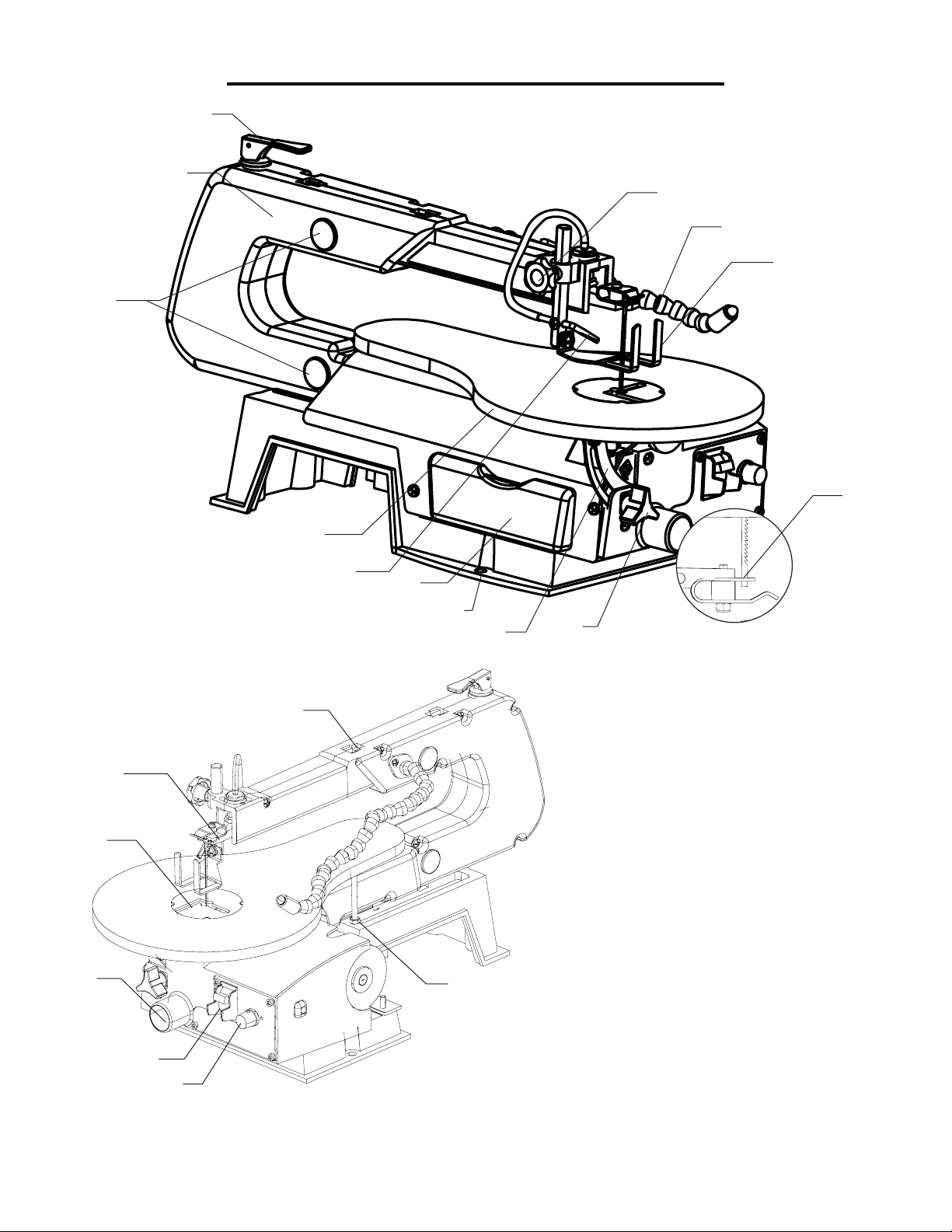
KNOW YOUR SCROLL SAW
A
B
L
M
K
J
D
E
F
G
H
I
A - Blade Tension Knob
T
B - Arm Housing
C - Rubber Bearing Covers
N
D - Table
E - Sawdust Blower
F - Storage Area
O
G - Base
H - Bevel Scale and Pointer
I - Table/Bevel Lock Knob
J - Lower Blade Holder
K - Blade Guard Foot
L - Blade Guard Root Lock Knob
P
S
M - LED Light
N - Upper Blade Holder
O - Table Insert
Q
R
P- Sawdust Collection Port
Q - ON/OFF Switch
R - Speed Control Knob
S - Table Adjusting Screw
T- Pinless Blade Holder
7
Page 8

ASSEMBLY AND ADJUSTMENTS
UNPACKING
Carefully unpack the scroll saw and all of its parts. Compare them against the list below. Do not discard the carton or any packaging until the scroll saw is completely assembled.
CAUTION: do not lift the saw by the arm that holds the blade. The saw will be damaged.
WARNING: To avoid injury from accidental startups, turn switch OFF and remove the plug from
the power source outlet before making any adjustments.
INCLUDES (Fig. 1)
B
A
A - Scroll saw with attached light
B - Extra pin blade
C
Fig. 1
STORAGE AREA (Fig. 2)
A convenient storage location
for the extra blade can be found
beneath the saw’s table.
Fig. 2
8
Page 9

ASSEMBLY AND ADJUSTMENTS
Prior to making adjustments, mount the scroll saw on a stable surface. See “Bench mounting the saw.”
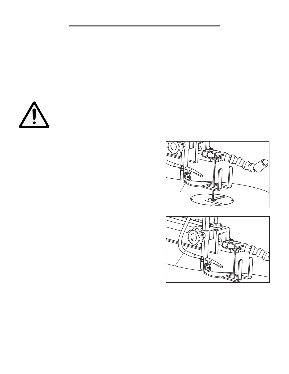
ALIGN THE BEVEL INDICATOR (Fig. 3-6)
The bevel indicator has been factory adjusted. It should be
rechecked prior to use for best operation.
1. Remove the blade guard foot (1) using a Phillips head
screwdriver (not included) to loosen the screw (2).
2. Loosen the table bevel lock knob (3) and move the table
until it is approximately at a right angle to the blade.
3. Loosen the locking nut (5) on the table adjusting screw (6)
under the table by turning it counter-clockwise. Lower the
table adjusting screw by turning it clockwise.
4. Use a combination square (7) to set the table exactly 90° to
the blade (8). If there is space between the square and blade,
adjust the table angle until the space is closed.
5. Lock the table bevel lock knob under the table (3) to prevent movement.
6. Tighten the adjusting screw under the table until the tip of
the screw touches the table. Tighten the lock nut.
1
2
Fig. 3
4
3
Fig. 4
7. Loosen the screw (4) holding the bevel scale pointer and
position pointer to 0°. Tighten the screw.
8. Attach the blade guard foot (1) so the foot rests flat against
the table. Tighten the screw (2) using a Phillips head screwdriver (not included).
Note: Avoid setting the edge of the table against the top of the
motor. This can cause excess noise when the saw is running.
6
5
Fig. 5
Fig. 6
9
Page 10
ASSEMBLY AND ADJUSTMENTS
BENCH MOUNTING THE SAW (Fig. 7-8)
Before operating the saw, it must be firmly mounted to a workbench or another rigid frame. Use the base of the saw
to mark and pre-drill the mounting holes. If the saw is to be used in one location, permanently secure it to the work
surface using wood screws if mounting to wood. Use bolts, washers, and nuts if mounting into metal. To reduce
noise and vibration, install a soft foam pad (not supplied) between the scroll saw and the workbench.
Note: mounting hardware not included.
WARNING - to reduce the risk of injury:
- When carrying the saw, hold it close to your body to avoid injury to your back. Bend your knees
when lifting the saw.
- Carry the saw by the base. Do not carry the saw by the power
cord.
- Secure the saw in a position where people cannot stand, sit, or
walk behind it. Debris thrown from the saw could injure people
standing, sitting, or walking behind it.
- Secure the saw on a firm, level surface where the saw cannot
rock. Make sure there is adequate room for handling and properly supporting the work piece.
Blade guard foot adjustment (Fig. 7 and 8)
When cutting at angles, the blade guard foot should be adjusted
so it is parallel to the table and rests flat above the work piece.
1. To adjust, loosen the screw (2), tilt the foot (1) so it is parallel
to the table, and tighten the screw.
2. Loosen the height adjustment knob (3) to raise or lower the
foot until it just rests on top of the work piece. Tighten the knob.
1
2
Fig. 7
Fig. 8
3
10
Page 11
ASSEMBLY AND ADJUSTMENTS
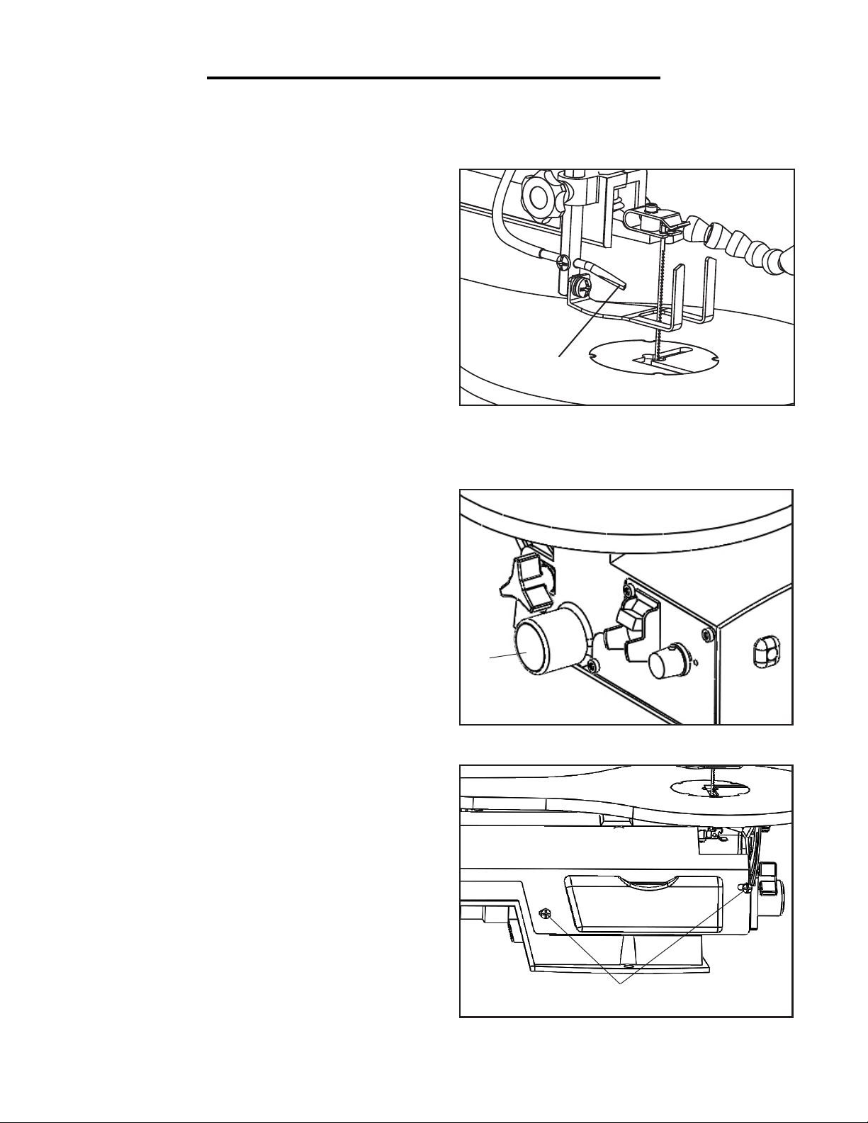
ADJUSTING THE DUST BLOWER (Fig. 9)
For best results, the dust blower tube (1) should be
adjusted to direct air at both the blade and the work
piece.
1
Fig. 9
SAWDUST COLLECTION PORT (Fig. 10 and
11)
This scroll saw allows a hose or vacuum accessory (not
provided) to be connected to the dust chute (2). If excessive sawdust buildup occurs inside the base, use a
wet/dry vacuum cleaner or manually remove sawdust
by removing the screws (3) and metal plate on the left
side of the saw. Reattach the metal plate and screws
before starting the saw. This will keep your saw cutting
efficiently.
2
Fig. 10
3
Fig. 11
11
Page 12

ASSEMBLY AND ADJUSTMENTS
BLADE SELECTION (Fig. 12)
This scroll saw accepts 5” length pin end and pinless blades, with a wide variety of blade
thicknesses and widths. The type of material and intricacies of cutting operations will determine the number of teeth per inch. Always select the narrowest blades for intricate curve
cutting and the widest blades for straight and large curve cutting operations. The following
table represents suggestions for various materials. Use this table as an example, but with
practice, personal preference will be the best selection method.
When choosing a blade, use very fine, narrow blades to scroll cut in thin wood 1/4” thick
or less.
Use wider blades for thicker materials but this will reduce the ability to cut tight curves. A
smaller blade width can cut circles with smaller diameters.
Note: Thinner blades will have more possibilities for blade deflection when cutting angles
are not perpendicular to the table.
TEETH
PER INCH
10 to 15 .11˝ .018˝
15 to 28 .055˝ to .11˝ .01 to .018˝
BLADE CARE
To maximize the life of your scroll saw blades:
1. Do not bend blades when installing.
2. Always set proper blade tension.
3. Use the right blade (see instruction on replacement blade packaging for
proper use).
4. Feed the work correctly into the blade.
5. Use thin blades for intricate cutting.
BLADE
WIDTH
BLADE
THICKNESS
BLADE SPM MATERIAL CUT
500 to 1200
SPM
800 to 1700
SPM
Medium turns on
1/4˝ to 1-3/4˝ wood,
soft metal, hardwood
Small turns on 1/8˝
to 1-1/2˝ wood, soft
metal, hardwood
9.5 to
15
15 to
28
Fig. 12
12
CAUTION: Any and all servicing should be performed by a qualified service center.
Page 13

14
13
12
11
10
9
8
7
6
5
4
3
2
1
ASSEMBLY AND ADJUSTMENTS
21
20
19
18
17
16
15
14
13
12
11
10
9
8
7
6
16
15
14
13
12
11
10
9
8
7
6
5
4
3
2
1
BLADE REMOVAL AND INSTALLATION (Fig. 13 to 15)
WARNING: To prevent personal injury, always turn saw OFF and disconnect the plug from
the power source before changing blades or making adjustments.
This saw uses pinned and pinless blades. Pinned blades are
thicker for stability and for faster assembly. They provide
faster cutting on a variety of materials.
Note: When installing pinned blades, the slot on the blade
holder must be slightly wider than the thickness of the blade.
After the blade is installed, the blade tension mechanism will
keep it in place.
1. To remove the blade, loosen the tension on it by lifting up
the blade tension lever. Turn the lever counterclockwise to
loosen the blade holder if necessary.
2. Remove the table insert. Carefully pry up on the table insert
to remove.
3. Push down on the upper blade holder to remove the blade
from the holder (2). Remove the blade from the lower blade
holder (3).
CAUTION: Install the blade with the teeth pointing downward.
4. To install the blade, hook the blade in the recess of the
lower blade holder (3).
1
Fig. 13
2
Fig. 14
5. While pushing down on the upper blade holder, insert the
blade into the slot of the holder.
7. Move the blade tension lever down and make sure the
blade pin is properly positioned in the blade holders.
8. Adjust the blade to the desired tension. Turning the blade
tension knob clockwise tightens the blade and turning the
knob counterclockwise loosens the blade.
8. Place the table insert back into place.
3
Fig. 15
13
Page 14
15
14
13
12
11
10
9
8
7
6
5
4
3
2
1
17
16
15
14
13
12
11
10
9
8
7
8
7
6
5
4
3
2
1
21
20
19
18
17
16
15
14
13
12
11
10
9
8
7
6
5
4
3
2
1
14
13
12
12
11
11
10
10
9
9
8
8
7
7
6
6
5
5
4
4
3
3
2
2
1
1
DRAWN
CHK'D
APPV'D
MFG
Q.A
UNLESS OTHERWISE SPECIFIED:
DIMENSIONS ARE IN MILLIMETERS
SURFACE FINISH:
TOLERANCES:
LINEAR:
ANGULAR:
FINISH:
DEBURR AND
BREAK SHARP
EDGES
NAME
SIGNATURE
DATE
MATERIAL:
DO NOT SCALE DRAWING
REVISION
TITLE:
DWG NO.
SCALE:1:5
SHEET 1 OF 1
A0
WEIGHT:
Pinless view1
ASSEMBLY AND ADJUSTMENTS
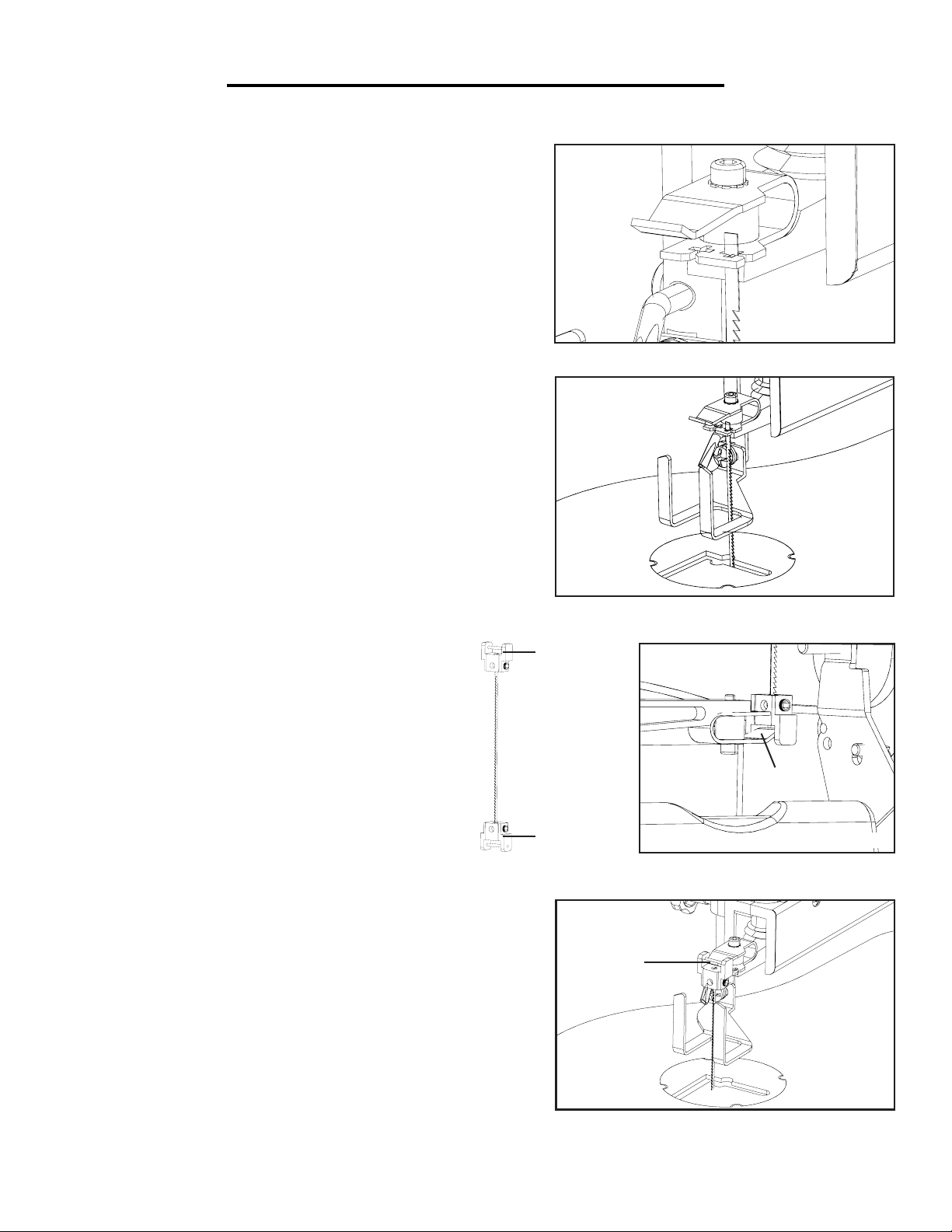
ADJUSTING THE BLADE DIRECTION (Fig. 16 & 17)
The WEN Scroll Saw accepts pinned blades in two different positions to accommodate a wider variety of workpieces.
Notice the two various slots for pinned blades that appear on
the head of the saw (Fig. 16).
Pinned blades can be placed in either of the two slots,
changing the direction of the blade by 90 degrees. A coinciding slot exists for each holder underneath the plate.
INSTALLING PINLESS BLADE (Fig. 18 & 19)
1. Remove the existing blade and table insert (see
Blade Removal and Installation).
Fig. 16
2. To install the pinless blade, loosen the thumb
screw on the lower blade attachment.
3. Install the blade into the lower blade attachment
and tighten the thumb screw. Hook the lower blade
attachment onto the curve of the bottom blade
holder found underneath the table (1).
4. Place the insert back into the table after carefully
inserting the blade through the table insert slot and
the pilot hole of the workpiece.
4. Insert the blade into the upper blade attachment.
Tighten the upper thumb screw to secure the blade.
5. Hook the upper blade attachment onto the top curve of the
upper blade holder (2).
6. Move the blade tension lever down and make sure the
blade attachments are properly secured and tensioned onto
the machine.
Fig. 17
Upper
Blade
Attachment
1
Lower
Blade
Attachment
Fig. 18
2
14
Fig. 19
Page 15

OPERATION
RECOMMENDATIONS FOR CUTTING
A scroll saw is basically a curve-cutting machine. It can also be used for straight cutting and beveling or angle cutting operations. Please read and understand the following items before attempting to use the saw.
1. When feeding the work piece into the blade do not force it against the blade. This could cause blade deflection. Allow the saw to cut the material by guiding the work piece into the blade as it cuts.
2. The blade teeth cut material ONLY on the down stroke.
3. Guide the wood into the blade slowly because the teeth of the blade are very small and remove wood only on
the down stroke.
4. There is a learning curve for each person using this saw. During that period of time it is expected that some
blades will break until you learn how to use the saw.
5. Best results are achieved when cutting wood one inch thick or less.
6. When cutting wood thicker than one inch, guide the wood slowly into the blade and take extra care not to
bend or twist the blade while cutting in order to maximize blade life.
7. Teeth on scroll saw blades wear out and the blades must be replaced frequently for best cutting results. Scroll
saw blades generally stay sharp for 1/2 hour to 2 hours of cutting.
8. To get accurate cuts, be prepared to compensate for the blade’s tendency to follow the wood grain.
9. This scroll saw is primarily designed to cut wood or wood products. For cutting precious and non-ferrous
metals, the variable control switch must be set at very slow speeds.
10. When choosing a blade, use very fine, narrow blades to scroll cut in thin wood 1/4” thick or less. Use wider
blades for thicker materials. This, however, will reduce the ability to cut tight curves.
11. Blades wear down faster when cutting plywood or very abrasive particle board. Angle cutting in hardwoods
also wears blades down faster.
15
Page 16

OPERATION
ON/OFF & SPEED CONTROL SWITCH (Fig. 20)
Always wait for the saw to come to a complete stop before restarting.
1. To turn the saw on, flip the ON/OFF switch to ON (2). When first starting the saw, it is best to move the speed
control knob (1) to the middle speed position.
2. Adjust the blade speed to the desired setting between 400 to 1600 strokes per minute (SPM). Turning the control knob clockwise increases speed; turning it counterclockwise reduces speed.
3. To turn the saw off, flip the ON/OFF switch back to OFF (2) in. Note: You can lock the scroll saw by removing
the tip of the switch. Just pry off the switch lock with your fingernails to prevent accidental operation.
WARNING: To avoid injury from accidental start-ups, always turn the switch OFF and unplug the scroll saw
before moving the tool, replacing the blade, or making adjustments.
FREEHAND CUTTING (Fig. 21)
1. Lay out desired design, or secure design to the work piece.
2. Raise the blade guard foot (1) by loosening the height adjustment knob (2).
3. Position the work piece against the blade and place the blade guard foot against the top surface of the work
piece.
4. Secure the blade guard foot (1) by tightening the height adjustment knob (2).
5. Remove the work piece from the blade prior to turning the scroll saw ON.
CAUTION: In order to avoid uncontrollable lifting of the work piece and to reduce blade breakage, do not turn
the switch on while the work piece is against the blade.
6. Slowly feed the work piece into the blade by guiding and pressing the work piece down against the table.
CAUTION: Do not force the leading edge of the work piece into the blade. The blade will deflect, reducing accuracy of cut, and may break.
7. When the cut is complete, move the trailing edge of the work piece beyond the blade guard foot. Turn the
switch OFF.
1
16
2
1
Fig. 20
Fig. 21
Page 17

ANGLE CUTTING (BEVELING) (Fig. 22)
1. Layout or secure design to work piece.
OPERATION
2. Move the blade guard foot to the highest position by loosening the height adjustment knob (1). Retighten.
3. Tilt the table to the desired angle by loosening the table bevel
lock handle (2). Move the table to the proper angle using the
degree scale and the pointer (3).
4. Tighten the table bevel lock handle (2).
5. Loosen the blade guard screw, and tilt the blade guard to the
same angle as the table. Retighten the blade guard screw.
6. Position the work piece on the right side of the blade. Lower
the blade guard foot against the surface by loosening the height
adjustment knob. Retighten.
7. Follow steps 5 to 7 under Freehand cutting.
INTERIOR CUTTING (Fig. 23
1. Lay out the design on the work piece. Drill a 1/4” hole in the
work piece.
1
2
Fig. 22
2. Remove the blade. See Blade removal and installation.
3. Place the work piece on the saw table with the hole in the
work piece over the access hole in the table.
4. Install a blade through the hole in the work piece.
5. Follow steps 3-7, under Freehand cutting.
6. When finished making the interior scroll cuts simply turn
the scroll saw OFF. Unplug the saw before removing the blade
from the blade holder. Remove the work piece from the table.
Fig. 23
17
Page 18

OPERATION
RIP OR STRAIGHT LINE CUTTING (Fig. 24)
1. Raise the blade guard foot (1) by loosening the height adjustment knob (2).
2. Measure from the tip of the blade to the desired distance. Position the straight edge parallel to the blade at that distance.
3. Clamp the straight edge to the table.
4. Recheck your measurements using the work piece to be cut
and make sure the straight edge is secure.
1
5. Position the work piece against the blade and place the blade
guard foot against the top surface of the work piece.
6. Secure the blade guard foot in place by tightening the height adjustment knob.
7. Remove the work piece from the blade prior to turning the scroll saw ON.
CAUTION: In order to avoid uncontrollable lifting of the work piece and reduce blade breakage, do not turn the
switch on while the work piece is against the blade.
8. Position the work piece against the straight edge prior to touching the leading edge of the work piece against the
blade.
9. Slowly feed the work piece into the blade, guiding the work piece against the straight edge and pressing the
work piece down against the table.
CAUTION: Do not force the leading edge of the work piece into the blade. The blade will deflect, reducing the
accuracy of the cut, and may even break.
10. When the cut is complete, move the trailing edge of the work piece beyond the blade guard foot. Turn the
switch OFF.
Fig. 24
18
Page 19

MAINTENANCE
WARNING: Always turn the switch OFF and unplug the power cord from the outlet before maintaining or
lubricating the scroll saw.
To ensure that the wood glides smoothly across the work surface, periodically apply a coat of paste wax (sold
separately) to the surface of the worktable. If the power cord is worn out or damaged in any way, replace it immediately. Do not attempt to oil the motor bearings or service the motor’s internal parts.
LUBRICATION (Fig. 25)
Lubricate the arm bearings after every 50 hours of use.
1. Turn the saw on its side and remove the cover.
2. Squirt a generous amount of SAE 20 oil (lightweight motor oil, sold separately) around the shaft and bearing.
3. Let the oil soak in overnight.
4. Repeat the above procedure for the opposite side of the
saw.
BLADES
To maximize the life of your scroll saw blades:
1. Do not bend blades when installing.
2. Always set proper blade tension.
3. Use the right blade (see instructions on replacement blade packaging for proper use).
4. Feed the work correctly into the blade.
5. Use thin blades for intricate cutting.
CAUTION: Any and all servicing should be performed by a qualified service center.
Fig. 25
19
Page 20

EXPLODED VIEW & PARTS LIST
20
Page 21

EXPLODED VIEW & PARTS LIST (3920C)
Item Stock # Description
1 3920B-001 Screw M5x8
2 3920B-002 Screw ST4.2x10
3 3920B-003 Side Cover
4 3920B-004 Nut M6
5 3920B-005 Spring Washer M6
6 3920B-006 Base
7 3920B-007 Oil Cap
8A 3920C-008A Left Arm Housing
8B 3920C-008B Right Arm Housing
9 3920B-009 Tension Bolt Assembly
10 3920B-010 Extension Spring
11 3920B-011 Pressure Plate
12 3920B-012 Spring Washer M4
13 3920B-013 Screw M4X10
14 3920C-013 Lower Arm
15 3920C-014 Upper Arm
16 3920C-015 Arm Bearing
17 3920C-016 Blast Pipe
18 3920B-018 Screw M5x6
20 3920B-020 Spring Washer M5
21 3920B-021 Screw M5x35
22 3920B-022 Screw M4x6
23 3920B-023 Bellows Cap
24 3920B-024 Screw M5x28
25 3920B-025 Table Lock Knob
26 3920B-026 Switch Fixing Board
27 3920B-027 Switch
28 3920B-028 Bellows
29 3920B-029 Fixing Plate
30 3920B-030 Bolt M6x20
31 3920C-030 Upper Blade Support
32 3920B-032 Washer M4
33 3920B-033 Screw M4x20
34 3920C-034 Support Cushion
35 3920B-076 Blade 15TPI
36 3920B-036 Screw M5x25
37 3920B-037 Big Cushion
38 3920B-038 Eccentricity Connector
39 3920B-039 Bearing 625Z (80025)
40 3920B-040 Nut M5
41 3920B-041 Clamping Board
42 3920B-042 Screw ST4.2x9.5
43 3920B-043 Washer
44 3920B-044 Screw M5x16
45 3920C-044 Lower Blade Support
46 3920B-046 Drop Foot Lock Knob
47 3920B-047 Drop Foot Fixing Pole
48 3920B-048 Screw M5x30
49 3920B-049 PCB
Item Stock # Description
50 3920B-050 Drop Foot
52 3920B-052 Screw M6x10
53 3920B-053 PVC Pipe
54 3920B-054 Big Washer M6
55 3920B-055 Screw M6x40
56 3920B-056 Bolt M6x16
57 3920B-057 Washer M6
58 3920B-058 Spring
59 3920B-059 Screw M6x25
60 3920B-060 Work Table Bracket
61 3920B-061 Pointer
62 3920B-062 Bevel Scale
63 3920B-063 Work Table
64 3920B-064 Work Table Insert
65 3920B-065 Speed Adjusting Knob
66 3920B-066 Screw M5x6
67 3920B-067 Power Cord
68 3920B-068 Screw M4x8
69 3920B-069 Screw M8x12
70 3920B-070 Eccentric Wheel
71 3920B-071 Motor
72 3920B-072 Switch Box
73 3920B-073 Cord Clamp
74 3920B-074 Screw
75 3920B-075 Poteniometer
76 3920B-076-2 Blade 18TPI Pinless
77 3920B-077 Screw M4x10
78 3920B-078 Screw M6x10
80 3920B-080 Foot
81 3920B-081 Wire Clip 1
82 3920B-082 Wire Clip 2
83 3920B-083 Screw M4x8
84 3920B-084 Transformer Box
85 3920B-085 Circuit board
86 3920B-086 Screw ST2.9x6.5
87 3920B-087 Cord Bushing 1
88 3920B-088 Cord Bushing 2
89 3920B-019 LED Assembly
91 3920B-091 Tool Box
92 3920B-092 Bolt M8x20
93 3920B-093 Bolt M6x80
94 3920B-094 Nut M4
95 3920C-095 Wrench S3
96 3920C-096 Wrench S2.5
97 3920C-097 Blade Adaptor
98 3920C-098 Set Screw M5x8
99 3920B-076-1 Blade 18TPI Pinned
100 3920C-100 Adaptor Location Screw
21
Page 22

LIMITED TWO YEAR WARRANTY
WEN Products is committed to building tools that are dependable for years. Our warranties are consistent with
this commitment and our dedication to quality.
LIMITED WARRANTY OF WEN CONSUMER POWER TOOLS PRODUCTS FOR HOME USE
GREAT LAKES TECHNOLOGIES, LLC (“Seller”) warrants to the original purchaser only, that all WEN consumer power tools will be free from defects in material or workmanship for a period of two (2) years from date of
purchase. Ninety days for all WEN products, if the tool is used for professional use.
SELLER’S SOLE OBLIGATION AND YOUR EXCLUSIVE REMEDY under this Limited Warranty and, to
the extent permitted by law, any warranty or condition implied by law, shall be the repair or replacement of parts,
without charge, which are defective in material or workmanship and which have not been misused, carelessly
handled, or misrepaired by persons other than Seller or Authorized Service Center. To make a claim under this
Limited Warranty, you must make sure to keep a copy of your proof of purchase that clearly defines the Date of
Purchase (month and year) and the Place of Purchase. Place of purchase must be a direct vendor of Great Lakes
Technologies, LLC. Third party vendors such as garage sales, pawn shops, resale shops, or any other secondhand
merchant void the warranty included with this product. Contact techsupport@wenproducts.com or 1-800-2321195 to make arrangements for repairs and transportation.
When returning a product for warranty service, the shipping charges must be prepaid by the purchaser. The product must be shipped in its original container (or an equivalent), properly packed to withstand the hazards of shipment. The product must be fully insured with a copy of the warranty card and/or the proof of purchase enclosed.
There must also be a description of the problem in order to help our repairs department diagnose and fix the
issue. Repairs will be made and the product will be returned and shipped back to the purchaser at no charge.
THIS LIMITED WARRANTY DOES NOT APPLY TO ACCESSORY ITEMS THAT WEAR OUT FROM
REGULAR USAGE OVER TIME INCLUDING BELTS, BRUSHES, BLADES, ETC.
ANY IMPLIED WARRANTIES SHALL BE LIMITED IN DURATION TO TWO (2) YEARS FROM
DATE OF PURCHASE. SOME STATES IN THE U.S., SOME CANADIAN PROVINCES DO NOT ALLOW LIMITATIONS ON HOW LONG AN IMPLIED WARRANTY LASTS, SO THE ABOVE LIMITATION MAY NOT APPLY TO YOU.
IN NO EVENT SHALL SELLER BE LIABLE FOR ANY INCIDENTAL OR CONSEQUENTIAL DAMAGES (INCLUDING BUT NOT LIMITED TO LIABILITY FOR LOSS OF PROFITS) ARISING FROM
THE SALE OR USE OF THIS PRODUCT. SOME STATES IN THE U.S. AND SOME CANADIAN
PROVINCES DO NOT ALLOW THE EXCLUSION OR LIMITATION OF INCIDENTAL OR CONSEQUENTIAL DAMAGES, SO THE ABOVE LIMITATION OR EXCLUSION MAY NOT APPLY TO
YOU.
THIS LIMITED WARRANTY GIVES YOU SPECIFIC LEGAL RIGHTS, AND YOU MAY ALSO HAVE
OTHER RIGHTS WHICH VARY FROM STATE TO STATE IN THE U.S., PROVINCE TO PROVINCE
IN CANADA AND FROM COUNTRY TO COUNTRY.
THIS LIMITED WARRANTY APPLIES ONLY TO PORTABLE ELECTRIC TOOLS, BENCH POWER TOOLS, OUTDOOR POWER EQUIPMENT AND PNEUMATIC TOOLS SOLD WITHIN THE
UNITED STATES OF AMERICA, CANADA AND THE COMMONWEALTH OF PUERTO RICO. FOR
WARRANTY COVERAGE WITHIN OTHER COUNTRIES, CONTACT THE WEN CUSTOMER SUPPORT LINE.
22
 Loading...