

Page 1

1
Page 2

Table of Contents
Technical data…………………………………………………………… 2
General safety rules……………………………………………………… 3
Additional safety rules…………………………………………………... 5
Electrical requirements………………………………………………..…. 8
Know your table saw……………………………………………………. 10
Unpacking……………………………………………………………….. 11
Assembly and adjustments……………………………………………… 12
Operation………………………………………………………………... 20
Maintenance…………………………………………………………….. 24
Trouble shooting………………………………………………………… 25
Exploded view………………………………………………………….. 26
Parts list…………………………………………………………………. 27
Warranty statement……………………………………………………… 30
Technical Data
Model: 3710
Motor: 120V, 60Hz, 15A, 4800rpm
Blade: 10 inch carbide tipped blade
Arbor: 5/8"
Depth of Cut at 90º: 3"
Depth of Cut at 45º: 2-3/8"
Bevel Angle Range: Left, 90º-45º
Table Height (with stand): 36"
Table Dimensions: 20"x26"
Weight: 46 lbs
2
Page 3

General Safety Rules
The purpose of safety symbols is to attract your attention to possible dangers. The safety symbols, and
the explanations with them, deserve your careful attention and understanding. The safety warnings do
not by themselves eliminate any danger. The instructions or warnings they give are not substitutes for
proper accident prevention measures.
Symbol Meaning
Safety Alert Symbol:
Indicated danger, warning, or caution, may be used in conjunction with other symbols or
pictographs. Always follow the safety precautions to reduce the risk of fire, electric shock
and personal injury.
NOTE: advising you of information or instructions is vital to the operation or maintenance of the
equipment.
Important
Servicing requires extreme care and knowledge and should be performed only by a qualified service
technician. For service, we suggest you return the tool to WEN PRODUCTS a division of Great Lakes
Technologies, LLC for repair. When servicing, use only identical WEN® replacement parts.
WARNING - Do not attempt to operate this tool until you have read thoroughly and
understand completely all instructions, safety rules, etc…contained in this manual. Failure
to comply can result in accidents involving fire, electric shock, or serious personal injury. Save this
operator’s manual and review frequently for continuing safe operation and instructing others who may
use this tool.
Safe operation of this power tool requires that you read and understand this operator’s manual and all
labels affixed to the tool. Safety is a combination of common sense, staying alert, and knowing how
your tool works.
―READ ALL INSTRUCTIONS‖ Failure to follow the safety rules listed below and other basic safety
precautions may result in serious personal injury.
Work Area
KEEP CHILDREN AWAY
Do not let visitors contact tool or extension cord. All visitors should be kept away from work area.
KEEP WORK AREAS CLEAN
Cluttered areas and benches invite accidents.
MAKE WORKSHOP CHILD-PROOF
With padlocks, master switches.
AVOID DANGEROUS ENVIRONMENTS
Don’t use power tools in damp or wet locations. Keep work area well lit. Do not expose power tools to
rain. Do not use tool in presence of flammable liquids or gases.
AVOID ACCIDENTAL STARTING
Make sure the switch is in the ―OFF‖ position before plugging in tool.
3
Page 4

NEVER STAND ON TOOL OR ITS STAND
Serious injury could occur if the tool is tipped or if the cutting tool is accidentally contacted. Do not
store materials on or near the tool such that it is necessary to stand on the tool or its stand to reach
them.
CHECK DAMAGED PARTS
Before further use of the tool, a guard or other part that is damaged should be carefully checked to
ensure that it will operate properly and perform its intended function. Check for alignment of moving
parts, mounting and any other conditions that may affect its operation. A guard or other part that is
damaged should be properly replaced.
Personal Safety
KNOW YOUR POWER TOOL
Read and understand the owner’s manual and labels affixed to the tool. Learn its application and
limitations as well as th e specific potential hazards peculiar to this tool.
DON’T OVERREACH
Keep proper footing and balance at all times.
STAY ALERT
Watch what you are doing. Use common sense. Do not operate
operate while under medication or while using alcohol or other drug.
DRESS PROPERLY
Do not wear loose clothing or jewelry. They can get caught in moving parts. Rubber gloves and nonskid footwear are recommended when working outdoors. Wear protective hair covering to contain long
hair.
USE SAFETY GOGGLES
Also face or dust mask if cutting operation is dusty, and ear plugs during extended periods of operation.
GUARD AGAINST ELECTRIC SHOCK
Prevent body contact with grounded surfaces. For example:
Pipes, radiators, ranges, refrigerator enclosures
DISCONNECT TOOL FROM POWER SOURCE
When not in use, before servicing, when changing blades, bits, cutters, etc.
KEEP GUARDS IN PLACE
In working order, and in proper adjustment and alignment.
REMOVE ADJUSTING KEYS AND WRENCHES
When not in use, before servicing, when changing blades, bits, cutters, etc.
All repairs, electrical or mechanical, should be attempted only by trained repairmen.
Use only WEN replacement parts; any others may create a hazard.
Use only accessories that are recommended by the manufacturer for your model. Accessories that may
be suitable for one tool may become hazardous when used on another tool.
4
the tool when you are tired. Do not
Page 5

Additional Safety Rules
Tool Care
DO NOT ALTER OR MISUSE TOOL
These tools are precision built. Any alteration or modification not specified is misuse and may result in
dangerous conditions.
AVOID GASEOUS AREAS
Do not operate electric tools in gaseous or explosive at mospheres. Motors in these tools normally
spark, and may result in a dangerous condition.
MAINTAIN TOOLS WITH CARE
Keep tools sharp and clean for better and safer performance. Follow instructions for lubricating and
changing accessories. Inspect tool cords periodically and if damaged, have repaired by authorized
service facility. Inspect extension cords periodically and replace if damaged. Keep handles dry, clean
and free from oil and grease.
Before connecting the tool to a power source (receptacle, outlet, etc.), be sure voltage supplied is the
same as that specified on the nameplate of the tool. A power source with voltage greater than that
specified for the tool can result in serious injury to the user — as well as damage to the tool. If in
doubt, DO NOT PLUG IN THE TOOL. Using a power source with voltage less than the nameplate
rating is harmful to the motor.
STABILITY OF SAW
Your table saw MUST BE BOLTED securely to a stand or workbench. In addition, if there is any
tendency for the table saw to tip over or move during certain operations such as cutting long, heavy
boards, use an auxiliary support.
LOCATION
Use the table saw in a well lit area and on a level surface, clean and smooth enough to reduce the risk
of trips and falls. Use it where neither the operator nor the casual observer is forced to stand in line
with the blade.
KICKBACK
Kickbacks can cause serious injury: A ―KICKBACK‖ occurs when a part of the workpiece binds
between the saw blade and the rip fence or other fixed object. Workpiece binding the blade due to
misalignment can also cause kickback. During kickback, workpiece rises from table and is thrown
toward the operator. Keep your face and body to one side of the saw blade, out of line with a possible
―KICKBACK‖.
KICKBACKS AND POSSIBLE INJURY CAN USUALLY BE AVOIDED BY:
a. Maintaining the rip fence parallel to the saw blade.
b. Keeping the saw blade sharp. Replacing or sharpening anti-kickback pawls when points become
dull.
c. Keeping saw blade guard, spreader and anti-kickback pawls in place and operating properly. The
spreader must be in alignment with the saw blade and the pawls must stop a kickback once it has
started. Check their action before ripping.
5
Page 6

d. NOT ripping workpiece that is twisted or warped or does not have a straight edge to guide along
the rip fence.
e. NOT releasing work until you have pushed it all the way past the saw blade.
f. Using a Push Stick for ripping widths of 2" to 6" and an auxiliary fence and Push Block for ripping
widths narrower than 2" (See ―Basic Saw Operation, Using the Rip Fence ―section.).
g. NOT confining the cut-off piece when ripping or cross -cutting.
h. When ripping, apply the feed force to the section of the workpiece between the sawblade and the
rip fence. Use
Push Stick or Push Block when appropriate (See item f. above).
PROTECTION: Eyes, hands, face, ears and body.
TO AVOID BEING PULLED INTO THE SPINNING TOOL,
DO NOT WEAR: Loose Fitting Gloves, Loose Clothing, Necktie, Jewelry
DO: TIE BACK LONG HAIR, ROLL LONG SLEEVES ABOVE ELBOWS
a. If any part of your saw is missing, malfunctioning, has been damaged or broken … such as the
motor switch, or other operating control, a safety device or the power cord … cease operating
immediately until the particular part is properly repaired or replaced.
b. Wear safety goggles and a face shield if operation is dusty. Wear ear plugs or muffs during
extended periods of operation. Small loose pieces of wood or other objects that contact the rear of
the revolving blade can be thrown back at the operator at excessive speed. This can usually be
avoided by keeping the guard and spreader in place for all ―THRU-SAWING‖ operations (sawing
entirely thru the work) AND by removing all loose pieces from the table with a long stick of wood
IMMEDIATELY after they are cut off.
c. Use extra caution when the guard assembly is removed for resawing, dadoing, rabbeting or
molding — replace the guard as soon as that operation is completed.
d. NEVER turn the saw ―ON‖ before clearing the table of all tools, wood scraps, etc., except the
workpiece and related feed or support devices for the operation planned.
e. NEVER place your face or body in line with the cutting tool.
• NEVER place your fingers and hands in the path of the saw blade or other cutting tool.
• NEVER reach in back of the cutting tool with either hand to hold down or support the
workpiece, remove wood scraps, or for any other reason. Avoid awkward operations and hand
positions where sudden slip could cause fingers or hand to move into a saw blade or other
cutting tool.
• DO NOT perform any operation ―FREEHAND‖ — always use either the rip fence or the miter
gauge to position and guide the work.
• NEVER use the rip fence when crosscutting or the miter gauge when ripping. DO NOT use the
rip fence as a length stop.
• NEVER hold onto or touch the ―free end‖ of the workpiece or a ―free piece‖ that is cut off,
while power is ―ON‖ and/or the saw blade is rotating.
• Shut ―OFF‖ the saw and disconnect the power cord when removing the table insert, changing
the cutting tool, removing or replacing the blade guard, or making adjustments.
• Provide adequate support to the rear and sides of the saw table for wider or long workpieces.
• Plastic and composition (like hardboard) materials may be cut on your saw. However, since
these are usually quite hard and slippery, the anti-kickback pawls may not stop a kickback.
Therefore, be especially attentive to following proper set-up and cutting procedures for ripping.
Do not stand, or permit anyone else to stand, in line with a potential kickback.
f. If you stall or jam the saw blade in the workpiece, turn saw ―OFF‖, remove the workpiece from the
saw blade, and check to see if the saw blade is parallel to the table slots or grooves and if the
6
Page 7

spreader is in proper alignment with the saw blade. If ripping at the time, check to see if rip fence
is parallel with the saw blade. Readjust as indicated.
g. NEVER gang crosscut — lining up more than one workpiece in front of the blade (stacked
vertically or horizontally outward on the table) and then pushing thru saw blade. The blade could
pick up one or more pieces and cause a binding or loss of control and possible injury.
h. DO NOT remove small pieces of cut-off material that may become trapped inside the blade guard
while the saw is running. This could endanger your hands or cause a kickback. Turn saw ―OFF‖
and wait until blade stops.
KNOW YOUR CUTTING TOOLS
Dull, gummy or improperly sharpened or set cutting tools can cause material to stick, jam, stall the
saw, or kickback at the operator. Minimize potential injury by proper cutting tool and machine
maintenance. NEVER ATTEMPT TO FREE A STALLED SAWBLADE WITHOUT FIRST
TURNING THE SAW OFF.
a. NEVER use grinding wheels, abrasive cut-off wheels, friction wheels (metal slitting blades) wire
wheels or buffing wheels.
b. USE ONLY RECOMMENDED ACCESSORIES.
c. Crosscutting operations are more conveniently worked and with greater safety if an auxiliary wood
facing is attached to the miter gauge.
d. Make sure the top of the cutting tool rotates toward you when standing in normal operating
position. Also make sure the cutting tool, arbor collars and arbor nut are installed properly. Keep
the cutting tool as low as possible for the operation being performed. Keep all guards in place
whenever possible.
e. Do not use any blade or other cutting tool marked for an operating speed less than 5000 R.P.M.
Never use a cutting tool larger in diameter than the diameter for which the saw was designed. For
greatest safety and efficiency when ripping, use the maximum diameter blade for which the saw is
designed, since under these conditions the spreader is nearest the blade.
f. Make sure the table insert is flush or slightly below the table surface on all sides except for rear
side. NEVER operate the saw unless the proper insert is installed.
THINK SAFETY
SAFETY IS A COMBINATION OF OPERATOR COMMON SENSE AND ALERTNESS AT ALL
TIMES WHEN THE TABLE SAW IS BEING USED.
Do not allow familiarity (gained from frequent use of your table saw) to become common place.
Always remember that a careless fraction of a second is sufficient to inflict severe injury.
The operation of any power tool can result in foreign objects being thrown into the eyes, which can
result in severe eye damage. Always wear safety goggles that comply with ANSI Z87.1 (shown on
package) before commencing power tool operation.
Some dust created by power sanding, sawing, grinding, drilling, and other construction activities
contains chemicals known to cause cancer, birth defects or other reproductive harm. Some
examples of these chemicals are:
• Lead from lead-based paints,
• Crystalline silica from bricks and cement and other masonry products, and
• Arsenic and chromium from chemically treated lumber.
Your risk from these exposures varies, depending on how often you do this type of work. To reduce
your exposure to these chemicals: work in a well ventilated area, and work with approved safety
equipment, such as those dust masks that are specially designed to filter out microscopic particles.
7
Page 8

Electrical Requirements
Ampere Rating
Total Length of Cord in feet
More Than
Not More Than
25
50
100
150 0 6
18
16
16
14 6 10
18
16
14
12
10
12
16
16
14
12
12
16
14
12
Not Recommended
Double Insulated Tools
Double Insulation is a design concept used in electric power tools which eliminates the need for the
three wire grounded power cord and grounded power supply system. It is a recognized and approved
system by Underwriter’s Laboratories, CSA and Federal OSHA authorities.
IMPORTANT: Servicing of a tool with double insulation requires care and knowledge of the system
and should be performed only by a qualified service technician.
WHEN SERVICING, USE ONLY IDENTICAL REPLACEMENT PARTS.
Extension Cords
In the event of a malfunction or breakdown, grounding provides a path of least resistance for electric
current and reduces the risk of electrical shock. Tools equipped with an electrical cord having an
equipment-grounding conductor must be plugged into a matching outlet that is properly installed and
grounded in accordance with all local codes and ordinances.
Do not modify the plug provided in any way. If the plug does not fit the outlet, have the proper outlet
installed by a qualified electrician.
The use of any extension cord will cause some loss of power. To keep this to a minimum and to
prevent overheating and motor burned-out; use the table below to determine the minimum wire size
(A .W .G.) of extension cord.
Use only three (3) wire extension cords that have three (3) prong grounding plugs, and three (3) pole
receptacles that accept the tool’s plug.
Minimum Gauge for Extension Cords (AWG)
(When using 120 V only)
Grounding Instructions
IN THE EVENT OF A MALFUNCTION OR BREAKDOWN, grounding provides the path of least
resistance for electric current and reduces the risk of electric shock. This tool is equipped with an
electric cord that has an equipment grounding conductor and a grounding plug. The plug MUST be
plugged into a matching outlet that is properly installed and grounded in accordance with ALL local
codes and ordinances.
DO NOT MODIFY THE PLUG PROVIDED. If it will not fit the outlet, have the proper outlet
installed by an electrician.
8
Page 9
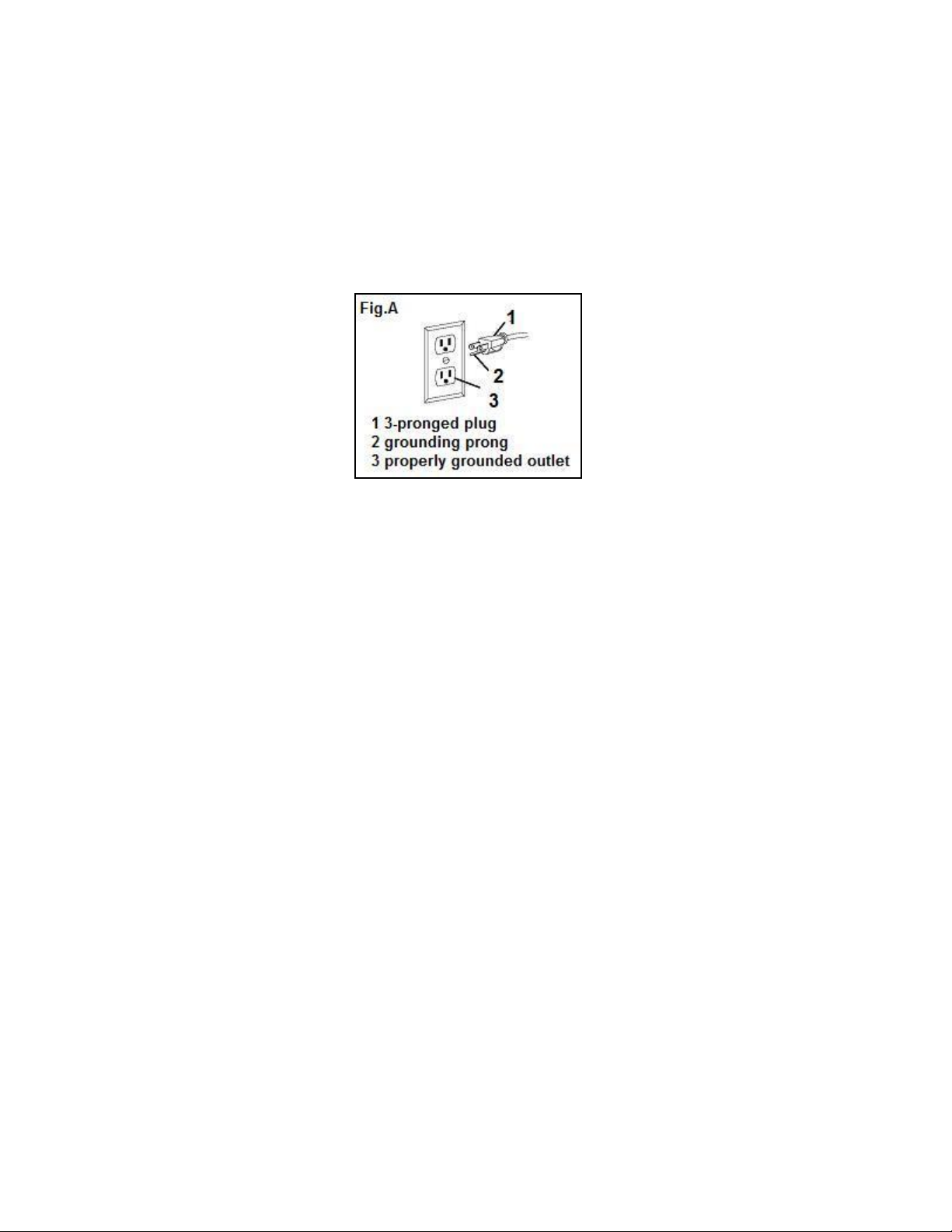
IMPROPER CONNECTION of the equipment grounding conductor can result in electric shock. The
conductor with the green insulation (with or without yellow stripes) is the equipment grounding
conductor. If repair or replacement of the electric cord or plug is necessary, DO NOT connect the
equipment grounding conductor to a live terminal.
CHECK with a licensed electrician or service personnel if you do not completely understand the
grounding instructions, or if you are not sure if the tool is properly grounded.
USE ONLY THREE-WIRE EXTENSION CORDS that have 3-pronged plugs and outlets that accept
the tool's plug as shown in Fig. A. Repair or replace a damaged or worn cord immediately.
CAUTION: In all cases, make certain the outlet in question is properly grounded. If you are not sure
if it is, have a licensed electrician check the outlet.
9
Page 10

Know Your Table Saw
A
Miter Gauge
G Hand Wheel
B
Blade Guard
H Leg Stand
C
Table
I ON/OFF Switch with Safety Key
D
Rip Fence Scale
J Blade Bevel Scale
E
Rip Fence Storage
K Miter Gauge Storage
F
Blade Bevel Locking Lever
10
Page 11

Unpacking
Item
Description
Qty
Item
Description
Qty
1
Table Saw
1 9
Push Stick
1 2 Miter gauge
1 10
Long Top Plate
2 3 Rip Fence
1 11
Short Top Plate
2 4 Wheel Handle
1 12
Long Support Plate
2 5 Blade Guard
1 13
Short Support Plate
2 6 Blade Wrench
2 14
Leg 4 7
Anti-kickback Device
1 15
Rubber Foot
4 8 Table Insert
2
Hardware Bag (not shown)
1
WARNING - to prevent accidental starting that could cause possible serious personal injury;
assemble all parts to your saw before connecting it to power supply. Saw should never be
connected to power supply when you are assembling parts, making adjustments, installing or
removing blades, or when not in use.
WARNING - if any parts are missing, do not operate this tool until the missing parts are
replaced. Failure to do so could result in possible serious personal injury.
Do not discard the packing materials until you have carefully inspected the saw, identified all parts,
and satisfactorily operated your new saw.
NOTE: if any parts are damaged or missing, do not attempt to plug in the power cord and turn the
switch on until the damaged or missing parts are obtained and are installed correctly.
11
Page 12

Assembly and Adjustments
WARNING! Prior to performing any assembly procedures, make sure the 10" table saw is
disconnected from its electrical power source.
Assembling the Leg Stand (Figure 1)
Warning: The stamped rails may have sharp edges. Be careful in handling the rails to
prevent being cut.
NOTE: Use the screws, washers, and lock nuts supplied in the
hardware bag to attach the pieces of the leg stand together. Do
not tighten the hardware completely until the leg stand is
completely assembled.
1. Attach the long top plates (10, Figure 1) to the legs (14,
Figure 1).
2. Attach the long support plates (12, Figure 1) to the legs (14,
Figure 1).
3. Place the front and rear short top plates (11, Figure 1) over
the side top plates (10, Figure 1). And attach to the legs (14,
Figure 1).
4. Attach the front and rear short support plates (13, Figure 1)
to the legs (14, Figure 1).
5. Tap the four rubber feet (15, Figure 1) onto the bottom of the legs (14, Figure 1).
Mounting the Table Saw to the Leg Stand (Figure 2)
NOTE: Mount the table saw to the leg stand using the
hardware supplied in the hardware bag.
1. Place the table saw onto the assembled leg stand so that the
four (4) mounting holes (1, Figure 2) in the base of the saw
are over the four (4) mounting holes in the front and rear
top plates (2, Figure 2).
2. Secure the table saw to the leg stand using four (4) bolts (3,
Figure 2), washers (4, Figure 2), and lock nuts (5, Figure 2).
IMPORTANT! When mounting the table saw to the leg stand,
DO NOT overtighten the mounting hardware.
Warning! Before operating table saw, securely fasten table saw to stand and entire unit must
be placed on solid, level surface.
Warning! Do not stand on table saw sand or use as ladder or scaffolding.
Warning! Do not use table saw if stand tips, slides, or moves in any way.
12
Page 13

Mounting Table Saw to Workbench (Figure 3 & 4)
If table saw is to be used in a permanent location, it should be fastened securely to a firm supporting
surface such as a stand or workbench, using the four mounting holes, 1 (Figure 3) two of which are
shown.
When mounting table saw to a workbench or plywood, holes should be drilled through the supporting
surface of the workbench or plywood and a opening MUST be made the same size as the opening in
the bottom of the saw using the dimensions illustrated (Figure 4), so the saw dust can drop through.
1. Each of the four mounting holes should be bolted securely using 5/16" hex nuts (not included).
Screw lengths should be 2-1/2" longer than the thickness of the bench top.
2. Locate and mark where the saw is to be mounted.
3. Drill four (4) 3/8" diameter holes through workbench.
4. Place table saw on workbench aligning holes in base with holes drilled in workbench.
5. Insert four (4) 5/16" screws and tighten.
13
Page 14

Mounting to Plywood (Figure 5)
An alternative method of securing your table saw is to fasten the saw base to a mounting board 24" x
24" minimum size to prevent saw from tipping while in use. Any good grade of plywood with a 3/4"
minimum thickness is recommended.
1. Follow instructions for mounting to workbench,
substituting a plywood board 24" x 24" minimum size
and using 5/16" flat head machine screws, flat washers,
and hex nuts (not included). Screw length must be at
least 2-1/2" more than the thickness of the mounting
board. Insert screws up through mounting board and
through base holes. Place flat washers on stud and
secure with hex nuts.
NOTE: For proper stability, holes must be counter sunk
on bottom side of plywood so screw heads are flush with
the bottom surface of the supporting board.
2. Securely clamp board (2, Figure 5) to workbench (3, Figure 5) using two or more ―C‖ clamps (4,
Figure5, not include).
Supporting surface where saw is to be mounted should be examined carefully after mounting to insure
that no movement can occur during use. If any tipping or walking is noted, secure the workbench or
stand before operating the table saw.
14
Page 15

90° and 45° Positive Stops Adjustment (Figure 6, 7 & 8)
Warning: To prevent personal injury, always disconnect the plug from power source before
making any adjustments.
The saw has positive stops that will quickly position the saw blade at 90° or 45° to the table. Make the
following adjustments only if necessary.
NOTE: 90° and 45° blade adjustment screws require a 5 mm Allen wrench (not supplied) and a 10
mm wrench or socket (not supplied) for adjustment. To access the 10 mm jam nut attached to the 90°
and 45° adjustment screws, turn the saw on its left side.
Make sure the saw is secure.
Adjusting the 90° Stop:
1. Raise the blade to the maximum height by turning the hand wheel
(1, Figure 6) counterclockwise.
2. Loosen the blade bevel locking knob (2, Figure 6). Push in the
blade elevation/tilting hand wheel (1, Figure 6) and rotate
clockwise as far as possible.
3. Place a combination square on the table and against the blade to
determine if the blade is at a 90° angle to the table (Figure 7).
4. If the blade is not at a 90° angle to the table, loosen the jam nut
(underneath table) and turn the 90° adjusting socket head screw (3, Figure 8) left to reduce the
angle or right to increase the angle.
Adjusting the 45° Stop:
1. Raise the blade to the maximum height by turning the
control wheel (1, Figure 6) counterclockwise.
2. Loosen the blade lock lever (2, Figure 6). Push in the blade
elevation/tilting control wheel (1, Figure 6) and rotate
counterclockwise as far as possible.
3. Place a combination square on the table and against the
blade to determine if the blade is at a 45° angle to the table
(Figure 7).
4. If the blade is not at a 45° angle to the table, loosen the jam nut (underneath table) turn the 45°
adjusting socket head screw (4, Figure 8) left to reduce the angle or right to increase the angle.
Adjusting the Blade Tilt Indicator:
1. When the blade is positioned at 90°, adjust the blade tilt
pointer to read 0° on the scale.
2. Loosen the holding screw, position pointer over 0° and tighten
the screw.
NOTE: Always make a trial cut on scrap wood when making
critical cuts. Measure for cut precision.
15
Page 16

Blade Parallel to Miter Gauge Groove Adjustment (Figure 9, 10 & 11)
Warning: To prevent personal injury, always disconnect the plug from power source before
making any adjustments.
Warning: If the blade is misaligned by more than 1/8", do not attempt to align or operate the
saw. Have a qualified service technician perform blade alignment.
1. Move the blade guard out of the way.
2. Raise the blade to the maximum height by turning the hand
wheel (1, Figure 9) counterclockwise. Push in the hand wheel
(1, Figure 9) and tilt the blade to 0°, then lock in place with
the bevel locking lever (3, Figure 9).
3. Select a tooth with a ―right set‖ on the end of the blade
closest to you. Mark it with a marker.
4. Place a combination square base (4, Figure 10) against the
left side of the right miter gauge groove (5, Figure 10).
5. Adjust the rule so it touches the front marked tooth. Lock the
ruler so it holds its position in the square assembly.
6. Rotate the blade bringing the marked tooth to the rear and
about 1/2" (13 mm) above the table.
7. Carefully, slide the combination square to the rear until the
ruler touches the marked tooth.
8. If the ruler touches the marked tooth at the front and rear
positions, no adjustment is necessary.
If the front and rear measurements are not the same, blade is not
parallel to the miter slot. Proceed to steps 9 –19 to perform the
adjustment.
9. Remove the combination square and stand the saw on its left
side so you can access the six adjustment nuts (6 & 7 Figure
11) that secure the axis rod to the table. Make sure the table
is secure.
Warning: Place folded pieces of cardboard over the blade
to protect your hands.
10. Us a 10 mm wrench to loosen all eight adjustment nuts
about 1/2 turn each.
11. Place the saw in the upright position.
12. Carefully move the blade to the left or right until it is
aligned properly.
13. Check the alignment with the combination square
(repeat steps 4 – 7).
14. Tighten the two front adjustment nuts (6, Figure 11).
Reach under the front and rear of the table with a
wrench to access these nuts.
15. Re-check the alignment. If additional adjustment is required, loosen only the two front adjustment
nuts (6, Figure 11) and repeat steps 4 & 5 until the blade is parallel to the miter slot. Tighten the
two front adjustment nuts (6, Figure 11).
16
Page 17

16. Stand the saw on its left side and tighten the four center adjustment nuts (7, Figure 11).
17. Place the saw upright and re-check the alignment to make sure the blade is parallel to the miter slot.
Removal and Installation of the Blade (Figure 12, 13 & 14)
Warning: Disconnect plug from power source before performing any assembly, adjustment
or repair to avoid possible injury.
NOTE: Clean blade of any excess oil before installation.
1. Remove the table insert (1, Figure 12).
2. Raise the blade (2, Figure 12) to the maximum height by
turning the hand wheel (3, Figure 12) counterclockwise,
3. Remove the arbor nut (4, Figure 13) and flange (5, Figure
13).
4. Clean any sawdust from both blade collars before
installing the blade. Install a 10" (25.4 cm) blade. Install
the saw blade onto the arbor with the blade teeth pointing
toward the front of the saw.
To avoid injury, do not use a blade larger or smaller than 10"
diameter and 5/8" arbor.
5. Install the flange 5 against the blade (2, Figure 13) and
thread the arbor nut (4, Figure 13) as far as possible by
hand. Ensure that the blade is flush against the inner blade
flange (6, Figure 13).
6. To tighten the arbor nut (4, Figure 14), use the open-end
wrench (7, Figure 14) and align the wrench jaws on the
flats of the flange to keep the arbor from turning. Place the
box-end wrench (8, Figure 14) on the arbor nut (4, Figure
14) and turn clockwise (to the rear of the saw table).
7. Install the table insert (1, Figure 12) in the table recess.
To avoid injury from a thrown workpiece, blade part, or blade
contact, never operate the saw without the proper insert in
place. Use the table insert when sawing. Use the dado insert
when using a dado blade.
Using Carbide-Tipped Blades
Handle carbide-tipped blades carefully. Carbide is very
brittle and can be easily damaged. Use caution when you
install, use or store the blades. Do not use a carbide-tipped
blade that is bent or has bent teeth, or if the blade has cracks,
is broken, or has missing/loose carbide tips. Do not operate
a carbide-tipped blade faster than its recommended speed.
17
Page 18

Installing the blade guard system
Warning: To prevent personal injury, always disconnect plug from power source before
installing or removing the blade guard.
POSITIONING THE RIVING KNIFE (Figure 15 & 16)
1. Remove table insert using finger hole.
2. Raise the blade as high as it will go and set it
perpendicular to table (0° on bevel scale) (Figure 15).
3. Rotate the riving knife release lever clockwise, so that
it points upward (Figure 15).
4. Pull riving knife towards release lever to disengage it
from the pins.
5. Slide the riving knife up to its highest position, so that
it is directly over the center of the blade (Figure 16).
6. Align holes in riving knife with pins and lock the
release lever by rotating it counterclockwise.
Push/pull riving knife to verify that it is locked in
place (Figure 16).
7. Replace table insert.
Installing the blade guard (Figure 17)
1. With one hand, hold the front of the barrier guard
assembly by the metal ―fork‖. With the other hand,
hold the guard release lever up (Figure 17).
2. Lower the rear of guard assembly and slip the cross
bar into the rear notch on top of the riving knife (Fig.
21).
3. Lower the front of the guard assembly until the metal
―fork‖ is parallel with the table (Fig. 22).
4. Press down on the guard release lever until you feel
and hear it snap into the locking position. Check that
the guard assembly is securely connected (Fig. 22).
18
Page 19

Installing the anti-kickback device (Figure 18)
While pulling out the attachment pin, attach the
Anti-Kickback Device into the flat recessed area A
of the riving knife (Figure 18).
Slide the Anti-Kickback Device down until it drops
into the recessed area – then release the attachment
pin such that the Anti-Kickback Device locks onto
the riving knife immediately behind the guard
assembly. Check that the attachment pin is securely
connected into locking hole.
Carefully raise and lower the pawls – when letting
go, the spring-loaded pawls must come down and
contact the table insert (Figure 18).
Note: The two installing are independent of each other, so the Anti-Kickback Device can be attached
before the Blade Guard.
19
Page 20
Operation
Warning: For your own safety, always observe the following safety precautions.
• Never make these cuts freehand (without using the miter gauge or other auxiliary devices)
because the blade could bind in the cut and cause a KICKBACK or cause your fingers or hand
to slip into the blade.
• Always tighten the miter gauge handle securely when in use.
• Remove rip fence from table during any operations which utilize the miter gauge.
• When cross cutting and the blade set at 90º to the table, the miter gauge can be used in either
slot on the table. When cross cutting and the blade is tilted, use slot on right side of table where
the blade is tilted away from your hands and miter gauge.
• Make sure blade guard is installed for all ―thru-sawing‖ operations (when sawblade cuts
entirely thru the thickness of the workpiece).
• Replace guard IMMEDIATELY after com pletion of dadoing, molding or rabbeting cuts.
• Have blade extend approximately 1/8" above top of work piece. Additional blade exposure
would increase the hazard potential.
• Do not stand directly in front of the blade in case of a THROWBACK (small cut-off piece
caught by the back of the blade and thrown toward the operator). Stand to either side of the
blade.
• Keep your hands clear of the blade and out of the path of the blade.
• If blade stalls or stops while cutting. TURN SWITCH OFF before attempting to free the blade.
• Do not reach over or behind the blade to pull the work piece through the cut … to support long
or heavy workpieces … to remove cut-off pieces of material or FOR ANY OTHER REASON.
• Do not pick up small pieces of cut-off material from the table. REMOVE them by pushing
them OFF the table with a long stick. Otherwise they could be thrown back at you by the rear
of the blade.
• Do not remove small pieces of cut-off material that may become TRAPPED inside the blade
guard while the saw is RUNNING. THIS COULD ENDANGER YOUR HANDS or cause a
KICKBACK. Turn the saw OFF. After the blade has stopped turning, lift the guard and remove
the piece.
• If workpiece is warped, place the CONCAVE side DOWN. This will prevent it from rocking
while it is being cut.
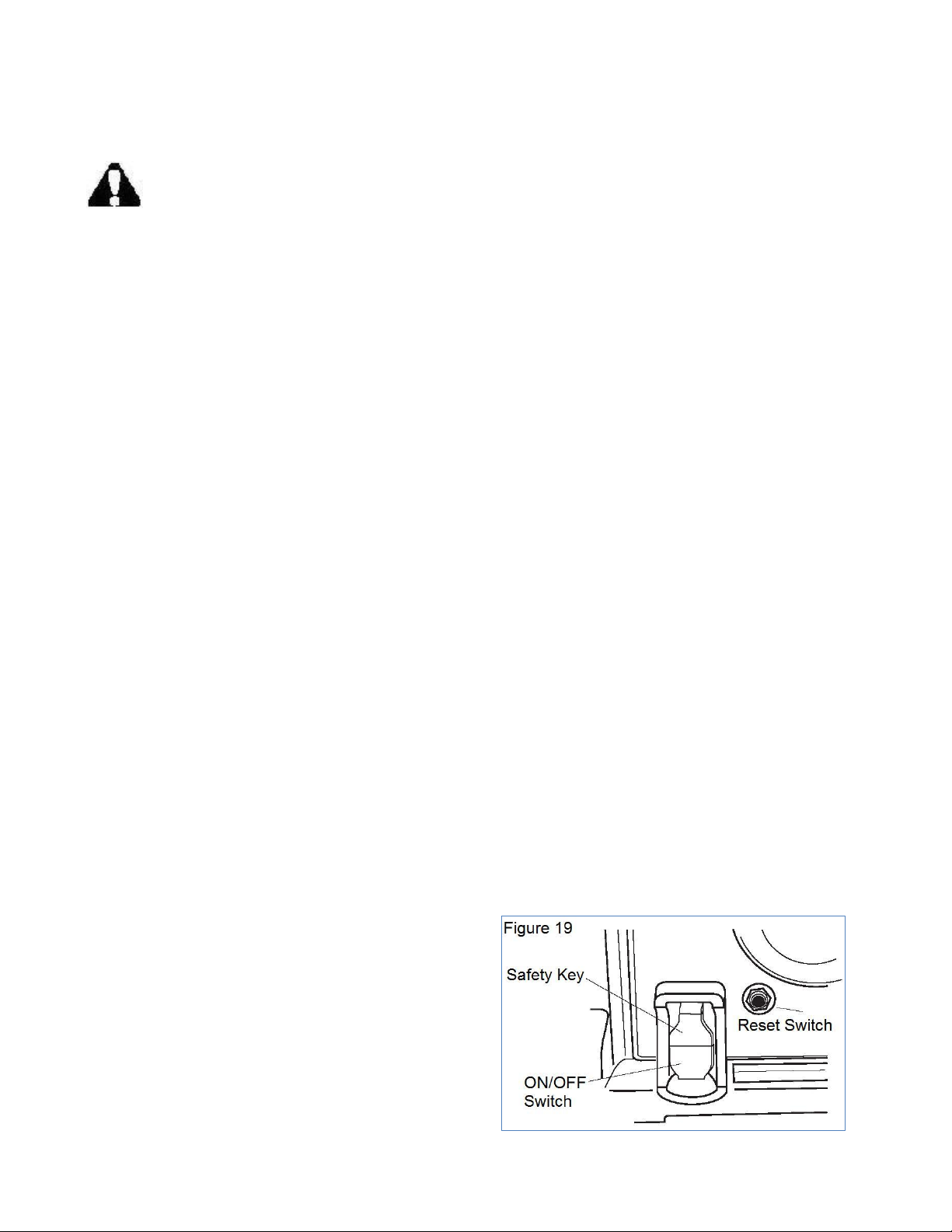
ON/OFF Switch (Figure 19)
The ON/OFF switch has a removable safety key to
protect against unauthorized use.
1. To turn the saw ON, insert the safety key into the
switch (Figure 19). Move the switch upward to the
ON position.
2. To turn the saw OFF, move the switch downward
to the OFF position.
3. To lock the switch in the OFF position, grasp the
safety key and pull it out of the switch. With the
20
Page 21

safety key removed, the switch will not operate.
NOTE: If the safety key is removed while the saw is running, the saw can be turned OFF, but cannot
be restarted without inserting the safety key.
Overload Reset Switch (Figure 19)
To prevent accidental startup if the overload reset switch is pushed, the ON/OFF switch should be in
the OFF position, and the plug should be removed from the power source while cool down takes place.
Overheating may be caused by misaligned parts or a dull blade. Inspect your saw for proper setup
before using it again.
This saw has an overload reset switch (Figure 19) that will allow the motor to be restarted after it shuts
off due to overloading or low voltage. If the motor stops during operation, perform the following:
1. Turn the ON/OFF switch to the OFF position.
2. Wait about five minutes for the motor to cool.
3. Push in the overload reset switch.
4. Turn the ON/OFF switch to the ON position.
Crosscutting (Figure 20)
Crosscutting is known as cutting wood across the grain, at 90°, or square with both the edge and the
flat side of the wood. This is done with the miter gauge set at 90° (Figure 20).
The graduations on the miter gauge provide accuracy for average
woodworking. In some cases where extreme ac curacy is
required, when making angle cuts, for example, make a trial cut
and then recheck it with an accurate square or protractor.
If necessary, the miter gauge head can be swiveled slightly to
compensate for any inaccuracy.
NOTE: The space between the miter gauge bar and the groove in
the table is held to a minimum during manufacturing.
For maximum accuracy when using the miter gauge, always ―favor‖ one side of the groove in the table.
In other words, don’t move the miter gauge from side to side while cutting but keep one side of the bar
riding against one side of the groove.
The miter gauge may be used in either of the grooves in the table. Make sure miter gauge bar is
engaged under table retainer tabs. Make sure lock handle is tightened securely to maintain angle.
When using the miter gauge in the LEFT hand groove, hold the workpiece firmly against gauge head
with your left hand, and grip the lock handle with your right hand.
When using the RIGHT hand groove, hold the workpiece with your right hand and the lock handle
with your left hand.
When cutting long workpieces, make sure the end is supported from the floor.
21
Page 22

Repetitive Cutting (Figure 21)
REPETITIVE CUTTING is known as cutting a quantity
of pieces the same length without having to mark each
piece (Figure 21).
When making repetitive cuts from a long work piece,
make sure it is supported.
Warning: Never use the rip fence as a length
stop because the cutoff piece could bind
between the fence and the blade causing a
kickback.
When making repetitive cuts, clamp a block of wood 3" long to the table at desired length to act as a
length stop.
Warning: When clamping the block, make sure that the end of the block is well in front of
the saw blade. Be sure it is clamped securely.
Slide the work piece along the miter gauge until it touches the block … hold it securely.
Make the cut … pull the work piece back … push the cut-off piece off the table with a long Push
Stick … DO NOT ATTEMPT TO PICK IT UP AS THIS COULD ENDANGER YOUR HANDS.
Miter Cutting (Figure 22)
MITER CUTTING is known as cutting wood at an angle
other than 90° with the edge of the wood. Follow the same
procedure as you would for crosscutting (Figure 22).
Adjust the miter gauge to the desired angle, and tighten
lock handle.
The miter gauge may be used in either of the grooves in the
table.
When using the miter gauge in the LEFT hand groove, hold
the workpiece firmly against the miter gauge head with your left hand, and grip the lock handle with
your right hand.
When using the RIGHT hand groove, hold the workpiece with your right hand and the lock handle
with your left hand.
Before cutting, always make sure you securely tighten the lock handle to maintain the desired angle.
22
Page 23

Bevel Crosscutting (Figure 23)
BEVEL CROSSCUTTING is the same as crosscutting
except that the wood is also cut at an angle … other than
90° with the flat side of the wood (Figure 23).
Adjust the blade to the desired angle and lock it.
Use the Miter Gauge in the groove to the RIGHT of the
blade. It cannot be used in the groove to the LEFT
because the blade guard will interfere.
Hold the workpiece with your right hand and the lock
knob with your left hand.
Compound Miter Cutting
COMPOUND MITER CUTTING is a combination of miter cutting and bevel crosscutting. The cut is
made at an angle other than 90° to both the edge and the flat side of the wood.
Adjust the miter gauge and the blade to the desired angle. Make sure miter gauge is locked.
23
Page 24

Maintenance
For your own safety, turn switch ―OFF‖ and remove plug from power source outlet before
maintaining or lubricating your saw.
Do not allow sawdust to accumulate inside the saw. Frequently blow out any dust that may accumulate
inside the saw cabinet and the motor. Clean your cutting tools with a Gum and Pitch Remover.
The cord and the tool should be wiped with a dry clean cloth to prevent deterioration from oil and
grease.
Warning: Certain cleaning agents and solvents can damage plastic parts. Some of these are:
gasoline, carbon tetrachloride, chlorinated cleaning solvents, ammonia and household
detergents which contain ammonia. Avoiding use of these and other types of cleaning agents
will minimize the possibility of damage.
A coat of automobile-type wax applied to the table will help to keep the surface clean and allow
workpieces to slide more freely.
If the power cord is worn or cut, or damaged in any way, have it replaced immediately.
Make sure the teeth of the ANTI-KICKBACK pawls are always
sharp. To sharpen:
1. Remove blade guard.
2. Rotate pawl toward rear of spreader so that teeth are above
top of spreader.
3. Hold spreader with left hand and place pawl over corner of
workbench (Figure 24).
4. Using a small round file (Smooth Cut) sharpen the teeth.
Warning: All repairs, electrical or mechanical, should
be attempted only by trained repairmen. Contact the
Service Center or Authorized Service Station. Use only
identical replacement parts, any other may create a hazard.
Lubrication
All motor bearings are permanently lubricated at the factory and require no additional lubrication.
Lubricate all mechanical parts where a pivot or threaded rod is present, with graphite or silicone.
These dry lubricants will not hold sawdust.
Care of Blades
Blades become dull even from cutting regular lumber. If you find yourself forcing the saw forward to
cut instead of just guiding it through the cut, chances are the blade is dull or coated with wood pitch.
24
Page 25

Trouble shooting
PROBLEM
CAUSE
SOLUTION
Saw will not start.
1. Saw not plugged in.
1. Plug in the saw.
2. Fuse blown or circuit breaker tripped.
2. Replace fuse or reset circuit breaker.
3. Cord damaged.
3. Have cord replaced by an authorized
service center.
Does not make accurate 45°
and 90° rip cuts.
1. Positive stop not adjusted correctly.
1. Check blade with square and adjust
positive stop.
2. Tilt angle pointer not set correctly.
2. Check blade with square and adjust
pointer to zero.
Material pinches blade when
ripping.
1. Rip fence not aligned with blade.
1. Check and adjust rip fence.
2. Warped wood, edge against fence is
not straight.
2. Select another piece of wood.
Material binds on splitter.
Splitter not aligned correctly with blade.
Check and align splitter with blade.
Saw makes unsatisfactory
cuts.
1. Dull blade.
1. Replace blade.
2. Blade mounted backwards.
2. Turn blade around.
3. Gum or pitch on blade.
3. Remove blade and clean with
turpentine and coarse steel wool.
4. Incorrect blade for work.
4. Change the blade.
5. Gum or pitch on table causing erratic
feed.
5. Clean table with turpentine and steel
wool.
Material kicked back from
blade.
1. Rip fence out of alignment.
1. Align rip fence with miter gauge.
2. Splitter not aligned with blade.
2. Align splitter with blade.
3. Feeding stock without rip fence.
3. Install and use rip fence.
4. Splitter not in place.
4. Install and use splitter (with guard).
5. Dull blade.
5. Replace blade.
6. The operator letting go of material
before it is past the saw blade.
6. Push material all the way past blade
before releasing work.
7. Miter angle lock knob is not tight.
7. Tighten knob.
Blade does not raise or tilt
freely.
Sawdust and dirt in elevation and tilting
mechanisms.
Brush or blow out loose dust and dirt.
Blade does not reach full
speed.
1. Extension cord too tight or too long.
1. Replace with adequate size cord.
2. Low house voltage.
2. Contact your electric company.
Machine vibrates
excessively.
1. Saw not mounted securely to stand or
workbench.
1. Tighten all mounting hardware.
2. Stand or bench on uneven floor.
2. Reposition on flat level surface. Fasten
to floor if necessary.
3. Damaged saw blade.
3. Replace blade.
Does not make 45° and 90°
cross cuts.
Miter gauge out of adjustment.
Adjust miter gauge.
WARNING: To avoid injury from an accidental start, turn the power switch off, remove the
safety key and remove the plug from the power source before making any adjustment.
25
Page 26

Exploded View
26
Page 27

Parts List
Item #
Stock #
Description
Qty
Item #
Stock #
Description
Qty
1
3710-001
Nut 1 41
3710-041
Spring washer
4
2
3710-002
Outer flange
1
42
3710-042
Socket head cap screw
4 3 3710-003
Blade 1 43
3710-043
Casing pipe
1
4
3710-004
Inner flange
1
44
3710-044
Flat washer
1 5 3710-005
Spring block circle
1
45
3710-045
Spin pin
1 6 3710-006
Front cover
1
46
3710-046
Socket head cap screw
1 7 3710-007
Bearing
1
47
3710-047
Casing pipe
1
8
3710-008
Spring block circle
1
48
3710-048
Nut 3 9
3710-009
Output axis
1
49
3710-049
Nut
6
10
3710-010
Half circle key
1
50
3710-050
Support iron
1
11
3710-011
Gear 1 51
3710-051
Spindle washer
3
12
3710-012
Spring block circle
1
52
3710-052
Mat plate
1
13
3710-013
Bearing
1
53
3710-053
Ruler
1
14
3710-014
Gear cover
1
54
3710-054
Caution sign
1
15
3710-015
Bearing
1
55
3710-055
Socket head cap screw
1
16
3710-016
Rotor 1 56
3710-056
Spindle washer
1
17
3710-017
Bearing
1
57
3710-057
Spindle
1
18
3710-018
Block wind cover
1
58
3710-058
Spring washer
1
19
3710-019
Stator 1 59
3710-059
Spindle washer
3
20
3710-020
Motor cover
1
60
3710-060
Nut
6
21
3710-021
Flat washer
4
61
3710-061
Nut 1 22
3710-022
Spring washer
4
62
3710-062
Casing pipe
1
23
3710-023
Socket head cap screw
4
63
3710-063
Screw rod
1
24
3710-024
Binding post
2
64
3710-064
Socket head cap screw
1
25
3710-025
Back cover
1
65
3710-065
Hand wheel
1
26
3710-026
Cable flat
1
66
3710-066
Flat washer
1
27
3710-027
Screw 2 67
3710-067
Handle
1
28
3710-028
Screw 1 68
3710-068
Screw
1
29
3710-029
Lead wire
1
69
3710-069
Nut
1
30
3710-030
Wire clip
1
70
3710-070
Flat washer
1
31
3710-031
Pin 1 71
3710-071
Locking handle
1
32
3710-032
Spring
1
72
3710-072
Locking piece
2
33
3710-033
Screw 2 73
3710-073
Screw 1 34
3710-034
Brush hold
2
74
3710-074
Pointer
1
35
3710-035
Carbon brush
2
75
3710-075
Locking piece
1
36
3710-036
Brush cover
2
76
3710-076
Limit board
1
37
3710-037
Screw 1 77
3710-077
Nut
1
38
3710-038
Spring washer
1
78
3710-078
Screw
1
39
3710-039
Flat washer
1
79
3710-079
Cover plate
1
40
3710-040
Flat washer
4
80
3710-080
Nut
1
27
Page 28

Item #
Stock #
Description
Qty
Item #
Stock #
Description
Qty
81
3710-081
Socket head cap screw
3
121
3710-121
Disk spring
2
82
3710-082
Spring washer
3
122
3710-122
Locking axis
1
83
3710-083
Flat washer
3
123
3710-123
Locking handle
1
84
3710-084
Swinging bracket
1
124
3710-124
Round pin
1
85
3710-085
Flat washer
1
125
3710-125
Screw 3 86
3710-086
Bolt 1 126
3710-126
Washer
3
87
3710-087
Push post
1
130
3710-130
Rubber plug
1
88
3710-088
Push board
1
131
3710-131
Screw 4 89
3710-089
Flat washer
1
132
3710-132
Spring washer
4
90
3710-090
Nut 1 133
3710-133
Flat washer
4
91
3710-091
Nut 1 134
3710-134
Screw 6 92
3710-092
Flat washer
1
135
3710-135
Bracing sheet
1
93
3710-093
Connecting rod
1
136
3710-136
Nut
6
94
3710-094
Binding post
1
137
3710-137
Screw 2 95
3710-095
Nut 1 138
3710-138
Cable flat
1
96
3710-096
Flat washer
1
139
3710-139
Jacket 1 97
3710-097
Nut 2 140
3710-140
Cable 1 98
3710-098
Nut 1 141
3710-141
Base
1
99
3710-099
Flat washer
1
142
3710-142
Grip slipper
1
100
3710-100
Pin 1 143
3710-143
Spring piece
1
101
3710-101
Nut 1 144
3710-144
Screw
1
102
3710-102
Flat washer
1
145
3710-145
Switch
1
103
3710-103
Holder
1
146
3710-146
Screw
4
104
3710-104
Nut 2 147
3710-147
Switch box cover
1
105
3710-105
Connecting rod
1
148
3710-148
Protector
1
106
3710-106
Binding post
2
149
3710-149
Switch box
1
107
3710-107
Connecting rod
1
150
3710-150
2 108
3710-108
Nut 1 151
3710-151
Plus screw
2
109
3710-109
Flat washer
2
152
3710-152
Spring washer
2
110
3710-110
Spring washer
2
153
3710-153
Flat washer
2
111
3710-111
Socket head cap screw
2
154
3710-154
Nut
2
112
3710-112
Nut 1 155
3710-155
socket head cap screw
2
113
3710-113
Flat washer
1
156
3710-156
Angle ruler button
1
114
3710-114
Socket head cap screw
3
157
3710-157
Bolt 1 115
3710-115
Spring washer
3
158
3710-158
Pointer
1
116
3710-116
Flat washer
3
159
3710-159
Screw
1
117
3710-117
Connecting piece
1
160
3710-160
Flat washer
1
118
3710-118
Splitter heel
1
161
3710-161
Spring washer
1
119
3710-119
Splitter
1
162
3710-162
Miter gauge
1
120
3710-120
Splitter flat
1
163
3710-163
Flat washer
1
28
Page 29

Item #
Stock #
Description
Qty
Item #
Stock #
Description
Qty
164
3710-164
lock knob
1
205
3710-205
Guiding rule
1
165
3710-165
lock knob cover
1
206
3710-206
Flat washer
1
166
3710-166
Ruler 1 207
3710-207
Splint
1
168
3710-168
Bolt 2 208
3710-208
Pull rod
1
169
3710-169
Back plate
1
209
3710-209
Spring
1
170
3710-170
Bolt 2 210
3710-210
Splint
1
171
3710-171
Screw
2
211
3710-211
Spring plate
1
172
3710-172
Spring
1
212
3710-212
Screw
1
173
3710-173
Cage 1 213
3710-213
Spring washer
1
174
3710-174
Back plate
1
214
3710-214
Flat washer
1
175
3710-175
Pin 1 215
3710-215
Pointer
1
176
3710-176
Slide post
1
216
3710-216
Adjusting knob
1
177
3710-177
Back plate
1
217
3710-217
Pin
1
178
3710-178
Slide post
1
218
3710-218
Holder
1
179
3710-179
Back plate
1
219
3710-219
Pin 1 180
3710-180
Screw
2
220
3710-220
Wobbler
1
181
3710-181
Screw
2
221
3710-221
Round pin
1
182
3710-182
Pin 1 222
3710-222
Nut
1
183
3710-183
Locking wheel
1
223
3710-223
Handle
1
184
3710-184
Pin 1 224
3710-224
Table
1
185
3710-185
Casing pipe
1
225
3710-225
Base plate
1
186
3710-186
Connecting rod
4
226
3710-226
Table insert
1
187
3710-187
Locking wheel
1
227
3710-227
Screw
2
188
3710-188
Pin 1 228
3710-228
Dust leg
1
189
3710-189
Socket head cap screw
2
229
3710-229
Flat washer
4
190
3710-190
Locking piece
1
230
3710-230
Spring washer
4
191
3710-191
Spring block circle
1
231
3710-231
Screw
4
192
3710-192
Kick paw
1
232
3710-232
Push stick
1
193
3710-193
Spacer sleeve
1
233
3710-233
Open spanner
1
194
3710-194
Kick plate
1
234
3710-234
Spanner
1
195
3710-195
Round pin
1
196
3710-196
Spacer sleeve
1
197
3710-197
Kick paw
1
198
3710-198
Spring block circle
1
199
3710-199
Tensional spring
1
200
3710-200
Lock pin
1
201
3710-201
Lock spring
1
202
3710-202
Pull knob
1
203
3710-203
Screw
2
204
3710-204
Lock washer
2
29
Page 30

Limited Two Years Warranty
WEN Products is committed to build tools that are dependable for years. Our warranties are consistent with this
commitment and our dedication to quality.
LIMITED WARRANTY OF WEN CONSUMER POWER TOOLS PRODUCTS FOR HOME USE
GREAT LAKES TECHNOLOGIES, LLC ("Seller") warrants to the original purchaser only, that all WEN consumer power
tools will be free from defects in material or workmanship for a period of two (2) years from date of purchase. Ninety days
for all WEN products, if the tool is used for professional use.
SELLER'S SOLE OBLIGATION AND YOUR EXCLUSIVE REMEDY under this Limited Warranty and, to the extent
permitted by law, any warranty or condition implied by law, shall be the repair or replacement of parts, without charge,
which are defective in material or workmanship and which have not been misused, carelessly handled, or misrepaired by
persons other than Seller or Authorized Service Center. To make a claim under this Limited Warranty, you must return the
complete power tool product; transportation prepaid, to Great Lakes Technologies, LL C – 501 Davis Road – Elgin, IL.
60123 with a copy of the original receipt which is legible and clearly defines Date of Purchase including month and year
and Place of Purchase.
THIS LIMITED WARRANTY DOES NOT APPLY TO ACCESSORY ITEMS SUCH AS CIRCULAR SAW BLADES,
DRILL BITS, ROUTER BITS, JIGSAW BLADES, SANDING BELTS, GRINDING WHEELS AND OTHER RELATED
ITEMS.
ANY IMPLIED WARRANTIES SHALL BE LIMITED IN DURATION TO TWO (2) YEARS FROM DATE OF
PURCHASE. SOME STATES IN THE U.S., SOME CANADIAN PROVINCES DO NOT ALLOW LIMITATIONS ON
HOW LONG AN IMPLIED WARRANTY LASTS, SO THE ABOVE LIMITATION MAY NOT APPLY TO YOU.
IN NO EVENT SHALL SELLER BELIABLE FOR ANY INCIDENTAL OR CONSEQUENTIAL DAMAGES
(INCLUDING BUT NOT LIMITED TO LIABILITY FOR LOSS OF PROFITS) ARISING FROM THE SALE OR USE
OF THIS PRODUCT. SOME STATES IN THE U.S. AND SOME CANADIAN PROVINCES DO NOT ALLOW THE
EXCLUSION OR LIMITATION OF INCIDENTAL OR CONSEQUENTIAL DAMAGES, SO THE ABOVE
LIMITATION OR EXCLUSION MAY NOT APPLY TO YOU.
THIS LIMITED WARRANTY GIVES YOU SPECIFIC LEGAL RIGHTS, AND YOU MAY ALSO HAVE OTHER
RIGHTS WHICH VARY FROM STATE TO STATE IN THE U.S., PROVINCE TO PROVINCE IN CANADA AND
FROM COUNTRY TO COUNTRY.
THIS LIMITED WARRANTY APPLIES ONLY TO PORTABL EELECTRIC TOOLS, BENCH POWER TOOLS,
OUTDOOR POWER EQUIPMENT AND PNUMATIC TOOLS SOLD WITHIN THE UNITED STATES OF
AMERICA, CANADA AND THE COMMONWEALTH OF PUERTO RICO. FOR WARRANTY COVERAGE WITHIN
OTHER COUNTRIES, CONTACT THE WEN CUSTOMER SUPPORT.
30
 Loading...