


Manual de Serviço
Bisturi Eletrônico Microprocessado
Modelos
SS-501LX & SS-501SX

Manual de Serviço (hosp) revisão: 00
Referência: 06_tri
Edição: Junho / 2017
Manual de Serviço
Bisturi Eletrônico Microprocessado
Modelos
SS-501LX & SS-501SX
contato para assistência técnica
Auto Suture do Brasil LTDA
Praça Agrícola La Paz Tristante, 131, setor 1, parte 8
Parque Industrial Anhanguera, Osasco | São Paulo, Cep: 06276-035
0800 179 944
e-mail: suporte@covidien.com

SS-501LX

CEP 14095-120
SS-501SX
Manufatura:
WEM Equipamentos Eletrônicos Ltda.
CGC no. 54 611 678/0001-30
Rua Marechal Mascarenhas de Moraes, 550
Ribeirão Preto - SP - Brasil

Manual de Serviço SS-501LX / SX
Índice
ASSUNTO
PÁG.
CAPÍTULO 1 – INFORMAÇÕES GERAIS
1.1 Introdução --------------------------------------------------------------------------------------------------------
1.2
1.2 Características Gerais ----------------------------------------------------------------------------------------
1.3
1.3 Aplicações --------------------------------------------------------------------------------------------------------
1.3
1.4 Saída Simultânea ----------------------------------------------------------------------------------------------
1.3
1.5 Princípio Físico e Fundamentos da Tecnologia do Equipamento, Aplicados para seu
Funcionamento e sua Ação ---------------------------------------------------------------------------------------
1.6 Instruções de Instalação --------------------------------------------------------------------------------------
1.6
1.7 Processo de Embalagem para Transporte --------------------------------------------------------------
1.10
2.1 Especificações Técnicas -------------------------------------------------------------------------------------
2.2
2.2 Saída de Potência em Carga Declarada -----------------------------------------------------------------
2.2
2.2.1 SS-501LX -------------------------------------------------------------------------------------------------
2.2
2.2.2 SS-501SX --------------------------------------------------------------------------------------------
2.3
2.3 Curva de Potência vs Carga ---------------------------------------------------------------------------------
2.4
2.3.1 SS-501LX -------------------------------------------------------------------------------------------------
2.4
2.3.2 SS-501SX ------------------------------------------------------------------------------------------------
2.5
2.4 Versão do Software --------------------------------------------------------------------------------------------
2.6
2.4.1 SS-501LX -------------------------------------------------------------------------------------------------
2.6
2.4.2 SS-501SX ------------------------------------------------------------------------------------------------
2.6
2.5 Placas -------------------------------------------------------------------------------------------------------------
2.7
2.6 Compatibilidade de Placas -----------------------------------------------------------------------------------
2.7
2.7 Conexões Internas ---------------------------------------------------------------------------------------------
2.8
2.8 Guia para Desmontagem do Equipamento --------------------------------------------------------------
2.9
2.8.1 Desmontagem da Tampa ----------------------------------------------------------------------------
2.9
2.8.2 Desmontagem do Painel Traseiro ------------------------------------------------------------------
2.10
2.8.3 Desmontagem do Painel Dianteiro -----------------------------------------------------------------
2.11
2.8.4 Desmontagem da Placa MB -------------------------------------------------------------------------
2.12
CAPÍTULO 3 – ROTINA DE MANUTENÇÃO
3.1 Manutenção Preventiva ---------------------------------------------------------------------------------------
3.2
3.2 Manutenção Corretiva -----------------------------------------------------------------------------------------
3.3
3.2.2 Problemas que Podem Ocorrer Durante o Procedimento Cirúrgico ----------------------
3.3
3.3 Self Teste ---------------------------------------------------------------------------------------------------------
3.4
CAPÍTULO 4 – ESQUEMAS ELÉTRICOS
4.1 Esquemas Elétricos --------------------------------------------------------------------------------------------
4.2
4.1.1 Placa CPU ------------------------------------------------------------------------------------------------
4.2
4.1.2 Placa MB -------------------------------------------------------------------------------------------------
4.3
CAPÍTULO 5 – CALIBRAÇÃO E AJUSTE
5.1 Calibração e Ajuste --------------------------------------------------------------------------------------------
5.2
5.1.1 Verificações de Potência e do Circuito de Placa -----------------------------------------------
5.2
CAPÍTULO 6 – PARTES E PEÇAS
6.1 Partes e peças --------------------------------------------------------------------------------------------------
6.2
6.1.1 Vista Explodida -----------------------------------------------------------------------------------------
6.2
6.1.2 Painel Dianteiro -----------------------------------------------------------------------------------------
6.3
6.1.2.1 Painel Dianteiro S S-501LX -----------------------------------------------------------------
6.3
6.1.2.1 Painel Dianteiro S S-501SX -----------------------------------------------------------------
6.4
6.1.3 Vista Explodida – Painel Traseiro SS-501LX / SS-501SX -----------------------------------
6.7
APÊNDICE
Esterilização de Acessórios --------------------------------------------------------------------------------------
A2
Suporte Técnico -----------------------------------------------------------------------------------------------------
A3
ÍNDICE
CAPÍTULO 2 – INFORMAÇÕES TÉCNICAS
1.4
Garantia ---------------------------------------------------------------------------------------------------------------- A2

Manual de Serviço SS-501LX / SX
Informações Gerais
Informações Gerais
CAPÍTULO 1
Para maior segurança:
a) Leia e entenda todas as instruções contidas no Manual de Utilização antes de
instalar ou operar este equipamento.
b) Este Manual de Serviço deve ser utilizado por técnicos e engenheiros com o
propósito de efetuar manutenções técnicas no equipamento WEM, modelos
SS-501LX e SS-501SX.
Este manual foi redigido originalmente no idioma Português.
ATENÇÃO
Página 1.1

Manual de Serviço SS-501LX / SX
Informações Gerais
1.1 – INTRODUÇÃO
As seguintes instruções de serviço são para uso somente por equipe técnica quali ficada
para instalação e manutenção do equipamento descrito neste manual. A WEM não se
responsabiliza pelo uso inadequado das informações aqui contidas.
O propósito deste manual é fornecer informações sobre instalação e manutenção do
equipamento SS-501LX / SS-501SX, tais como, informações técnicas, rotina de manutenção,
critérios de aceitação para calibração e ajuste, entre outros.
A WEM reserva o direito de efetuar modi ficações neste manual ou no e quipamento sem
aviso prévio.
Todos os direitos reservados. O conteúdo deste manual não poderá ser reproduzido ou
copiado sob qualquer forma sem autorização por escrito da WEM Equipamentos Eletrônicos
Ltda.
⇒ OBSERVAÇÃO: Ant es de iniciar a manutenção, leia atentamente o Manual de Utilização
correspondente, para melhor familiarizar-se com a operação do equipamento e os princípios
da eletrocirurgia.
Manual de Serviço revisão 1
O modelo SS-501LX foi incluído no manual de serviços a partir desta revisão.
Característica do SS-501SX em relação ao manual de serviços revisão 0:
- Excluída a tecla ALT;
- Separadas as funções de coagulação e bipolar para teclas individuais para cada
função;
- Conexão de acessórios no painel frontal modificado para o padrão universal.
# Identificação da versão de software e de número de série envolvidos. #
Este manual de serviço foi desenvolvido de acordo com às versões de software
‘SS_501LX_F.3.7’ / ‘SS_501SX_F.3.7’ e at ende aos números de série:
SS-501LX: ‘LAC + 7 dígitos’.
SS-501SX: ‘CAC + 7 dígitos’.
Para versões anteriores ou posteriores, favor consultar o manual de serviço
correspondente, a fim de verificar se esta revisão de manual é apropriada para os serviços
em questão.
Informação Complementar:
IDENTIFICAÇÃO DA 2ª E DA 3ª EDIÇÃO DA NORMA NBR IEC 60.601-1
A identificação é feita pelo número de série, como segue:
NBR IEC 60.601-1, 2ª edição
Os equipamentos WEM possuíam identificação de número de série de 5 dígitos numéricos
até aproximadamente dezembro de 2015. A partir de então passou a possuir 3 letras e 7
dígitos numéricos. A nova identificação do equipamento SS-501SX de 2ª edição é feita a partir
da numeração ‘CAA + 7 dígitos’
NBR IEC 60.601-1, 3ª edição
A identificação do equipamento SS-501SX de 3ª edição é feita a partir da numeração ‘CAB +
7 dígitos’.
Página 1.2

Manual de Serviço SS-501LX / SX
Informações Gerais
1
FULGURATE
FULGURATE
-----------
1.2 – CARACTERISTICAS GERAIS
Características
- Totalmente microprocessado;
- 12 funções de corte: puro, blend 1, 2 e 3 (com e sem High Cut), Ecut 1, 2, 3 e 4;
- 4 modos de coagulação: fulgurate, forced, desiccate e soft, que permitem ajustar o
efeito e a área de aplicação durante a coagulação do tecido;
- 4 modos de bipolar: bipolar, bipolar CUT, microbipolar e macrobipolar;
- 3 displays digitais independentes para corte, coagulação e bipolar;
- Pedais independentes para monopolar 1, monopolar 2 e bipolar;
- Comando por caneta manual e por pedal;
- Permite a utilização das duas saídas monopolares po r caneta c omando manual ou
por pedal;
- Sistema PPM que monitora o contato da placa-paciente automaticamente;
- Bargraph que indica o nível de contato da placa-paciente;
- Função Recall que permite a recuperação dos últimos valores de potência
ajustados no display;
- Função Remote que permite o ajuste de potência no display por meio da caneta
de comando manual;
- Permite conexão ao coagulador por plasma de argônio, modelo Argon 4.
Características do SS-501LX
- 300 watts de corte puro.
Características do SS-501SX
- 400 watts de corte puro.
1.3 – APLICAÇÕES
Indicado para cirurgias como ressecção transuretral e eletrovaporização de próstata,
cirurgias gastroenterológicas, cardíacas, ginecológicas, proctológicas, ortopédicas,
neurológicas, endoscópicas e muitas outras.
⇒ OBSERVAÇÃO:
A função ECUT foi especialmente desenvolvida para cirurgias endoscópicas como
polipectomia, ESD e mucosectomia.
As funções de corte com High Cut possibilitam um excelente desempenho em tecidos de
alta impedância.
Os modos High Cut, Macrobipolar e Bipolarcut possuem sistema de auxílio a inicialização
dos cortes, denominado EZCut®. O sistema EZCut® permite trabalhar com potências
médias mais baixas, uma vez que entrega potência no início do corte conforme a
necessidade. Dessa maneira, a entrega de energia ao paciente é menor e tem-se redução
nos riscos, aumento da vida útil de acessórios e redução no tempo de procedimento. O
sistema EZCut® é ideal para os procedimentos de ressecção transuretral e endoscopia.
1.4 – SAÍDA SIMULTÂNEA
É possível a seguinte combinação de acionamento simultâneo:
MONOPOLAR 1 MONOPOLAR 2 BIPOLAR
Página 1.3

Manual de Serviço SS-501LX / SX
Informações Gerais
1.5 – PRINCÍPIO FÍSICO E FUNDAMENTOS DA TECNOLOGIA DO
EQUIPAMENTO , APLICADOS PARA SEU FUNCIONAMEN TO E SUA AÇÃO
A eletrocirurgia consiste no uso de corrente elétrica de radiofrequência (RF) para cortar
tecido ou coagular. Correntes elétricas de baixa frequência (abaixo de 100.000 Hz) podem
provocar estimulação neuromuscular o que poderia eletrocutar o paciente ou causar a
sensação de choque.
Existem bisturis elétricos que trabalham em frequências de até 4.000.000 Hz (4 MHz),
porém fica muito difícil manter essas correntes de alta frequência dentro do fio, devido à
ação de capacitâncias e indutâncias parasitas. Os bisturis valvulados geralmente
trabalham em frequências próximas de 4 MHz. Os equipamentos modernos
transistorizados trabalham em frequências mais baixas. O SS-501LX/SS-501SX trabalha
em frequências de até 390.000 Hz (390 KHz), que é uma solução de compromisso entre
esses dois extremos. Existem basicamente três efeitos cirúrgicos que podem ser obtidos
através da eletrocirurgia: dessecação ou cauterização, corte eletrocirúrgico e fulguração.
Dessecação
Dos três efeitos cirúrgicos, a dessecação é tecnicamente a mais simples porque qualquer
forma de onda, de corte ou de coagulação pode ser utilizada, sendo necessários apenas
níveis baixos de potência. Consiste na coagulação sem faiscamento. A corrente elétrica
passa através do tecido provocando aquecimento do mesmo e, portanto, retirando
lentamente a água nele contida. Como a dessecação deve ser realizada com o eletrodo
ativo em bom contato elétrico com o tecido, é importante que o eletrodo seja mantido limpo
de tecido seco ou carbonizado. Pode ser realizada utilizando-se as saídas monopolar ou
bipolar (com exceção do modo Bipolar Cut), sendo que as saídas Bipolar e Micro Bipolar
são otimizadas para dessecação e não produzem corte ou fulguração. Mesmo em níveis
de potência elevados haverá pouca tendência a cortar ou fulgurar quando se utiliza a saída
bipolar (com exceção dos modos Macro Bipolar ou Bipolar Cut). A saída monopolar é
projetada, em princípio, para o corte e fulguração. Quando a mesma for usada para
dessecação devem-se utilizar níveis baixos de potência para que se tenha um mínimo
efeito de corte ou coagulação. A dessecação com o SS-501LX/SS-501SX pode ser feita
com a for m a de o n d a DES I CC ATE ou SOFT. O nível exato de potência depende da área
do eletrodo ativo, pois, quanto maior a área de contato, mais corrente será necessário
para produzir a mesma densidade de corrente. A coagulação através de pinça bipolar é
um exemplo prático de dessecação. A dessecação também ocorre quando o cirurgião
utiliza uma pinça hemostática monopolar para pinçar um vaso e estancar um
sangramento. As formas de onda são importantes apenas no corte e na fulguração, como
veremos a seguir.
Coagulação de baixa potência sem faiscamento
Eletrodo em bom contato com o tecido
Coagulação profunda que se espalha radialmente
Escara relativamente macia de cor marrom claro
Corrente típica = 0,5 Amp RMS
Página 1.4

Manual de Serviço SS-501LX / SX
Informações Gerais
Corte Eletrocirúrgico
Consiste no aquecimento das células do tecido tão rapidamente que elas explodem pelo
vapor produzido internamente. Este processo também é conhecido por vaporização
celular. O calor gerado é dissipado pelo vapor não havendo, portanto, condução para as
células adjacentes. Quando o eletrodo é deslocado e entra em contato com novas células
de tecido, estas explodem produzindo a incisão. É importante lembrar que o corte
eletrocirúrgico é obtido através de faiscamento pelo tecido. A forma de onda de corte do
SS-501LX/SS-501SX é uma senóide contínua na frequência de trabalho do bisturi (390
kHz).
Eletrodo separado do tecido por fina camada de vapor
Faíscas curtas e intensas vaporizam as células
Pequena hemostasia
Corrente típica = 0,1 Amp RMS
Fulguração
Consiste na geração de faiscamento do eletrodo para o tecido com mínimo efeito de corte.
A fulguração permite a coagulação de grandes sangramentos. A saída de coagulação do
SS-501LX/SS-501SX é otimizada para produzir fulguração. A forma de onda de
coagulação consiste de pacotes de senóide de rádio frequência de curta duração. A
frequência da senóide é de 250 KHz e os pacotes ocorrem com frequência de
aproximadamente 30 KHz (30.000 vezes por segundo). A característica mais importante
da forma de onda de fulguração é a pausa entre cada pacote.
Uma boa forma de onda de fulguração pode faiscar para o tecido com efeito de corte
insignificante porque as faíscas longas dispersam mais calor e o efeito de aquecimento é
intermitente. A temperatura da água no interior das células não se eleva o suficiente para
provocar a explosão pelo vapor gerado. Desse modo, as células são desidratadas
lentamente sem produzir incisão. Os elevados picos de tensão da forma de onda de
coagulação podem fazer a corrente circular através de resistências muito altas. Desse
modo é possível fulgurar durante um longo tempo, mesmo após ter sido totalmente
eliminada a água do tecido, e realmente carbonizá-lo. É interessante notar que o termo
coagulação é utilizado para indicar tanto dessecação como fulguração. A principal
diferença entre fulguração e dessecação é que a primeira sempre produz necrose,
dependendo da densidade de corrente utilizada. A fulguração é sempre mais eficiente para
produzir necrose e em geral requer apenas um quinto da corrente necessária para
dessecação.
Faíscas longas produzem primeira coagulação superficial, evoluindo para
Eletrodo afastado do tecido
necrose mais profunda na medida em que a fulguração continua
Escara dura e negra
A fulguração é usada para coagular grandes sangra mentos
Corrente típica = 0,1 Amp RMS
Página 1.5

Manual de Serviço SS-501LX / SX
Informações Gerais
Corte Misto (Blend)
Assim como a fulguração, a forma de onda de Blend consiste de pacotes de senóide. A
diferença consiste em que esses pacotes possuem maior duração. A forma de ond a de
Blend produz um corte com efeito hemostático isto é, as paredes da incisão ficam bem
fulguradas, dependendo do tamanho e diâmetro do eletrodo. Quanto mais fino o ele trodo,
mais liso é o corte (menos fulgurado).
O SS-501LX/SS-501SX possui 03 níveis de Blend. O Blend 1 tem efeito hemostático
mínimo, Blend 2 tem efeito hemostático moderado e o Blend 3 tem efeito hemostático
máximo.
Forma de onda de corte
Forma de onda de coagulação
Forma de onda de Blend
1.6 – INSTRUÇÕES DE INSTALAÇÃO
Preparação para Uso
- Conecte o cabo de alimentação no conector apropriado do painel traseiro;
- Coloque o interruptor liga/desliga localizado no painel traseiro na posição OFF
(desligado);
- Conecte o plugue de força a uma tomada aterrada;
- Coloque o interruptor liga/desliga na posição ON (ligado). No painel dianteiro
- superior direito deverá acender o led verde – POWER e o âmbar – STAND BY
- indicando que estará no modo de espera;
- Prepare-o para cirurgia monopolar ou bipolar, conforme abaixo;
- Pressione uma vez a tecla STAND BY, localizada no painel frontal, para colocar o
gerador no modo operacional.
Preparação para Cirurgia Monopolar.
Estando o equipamento já conectado à rede elétrica, siga os passos a seguir
preparando o equipamento para cirurgia monopolar.
- Conecte o pedal monopolar no conector fêmea MONOPOLAR FOOTSWITCH 1
ou MONOPOLAR FOOTSWITCH 2, localizado no painel traseiro. O conector
macho do pedal deve ser encaixado até ouvir-se um "clique" indicando que a
conexão está adequada. Para remover o pedal basta pressionar o botão no próprio
conector do painel traseiro, ao mesmo tempo em que se puxa o conector macho
para trás.
Página 1.6

Manual de Serviço SS-501LX / SX
Informações Gerais
⇒
⇒
- Conecte o cabo de placa à placa. O cabo PC-10 possui dois pinos com rosca que
devem ser rosqueados às duas buchas com rosca da placa reutilizável de aço inox
PP-04, normalmente fornecida com o equipamento. Caso utilize placas
descartáveis auto-adesivas comuns ou dividas ou tipo PPM (REM ), deve-se utilizar
o cabo PC-09 conectando a garra à lingueta da placa adesiva (ver Função PPM).
- Conecte a outra extremidade do cabo de placa ao borne PATIENT localizado no
painel dianteiro inferior.
Nota: o SS-501LX/SS-501SX detecta automaticamente o tipo de placa utilizada
(comum-PLC ou dividida-PPM) e a área de contato entre a placa e o paciente quando
a placa dividida estiver sendo utilizada.
- Conecte a outra extremidade do cabo de placa ao borne PATIENT no painel
dianteiro inferior.
- Conecte a caneta com comando manual na saída MONOPOLAR 1 ou
MONOPOLAR 2. Também pode ser usada uma caneta simples com acionamento
pelo pedal, só que o pino da caneta simples deverá ser conectado no borne
esquerdo da saída MONOPOLA R 1 ou MONOP OLAR 2. Nota: Podem-se também
conectar as saídas MONOPOLAR 1 ou MONOPOLAR 2 outros acessórios tais
como pinça monopolar, acessórios monopolares para cirurgia vídeo-laparoscópica,
etc;
- Selecione a função desejada, a fim de acender o indicador da função
correspondente;
- Ajuste a potência desejada através das teclas de aumento ou diominuição de
potência.
Utilização de Placas Adesivas Divididas – SISTEMA PPM
Para utilizar a placa adesiva dividida siga os passos abaixo:
- Conecte a placa ao cabo e ao equipamento conforme descrito anteriormente;
- Cole a placa ao paciente no local apropriado para a cirurgia em questão, certificando-se de
que a mesma está bem aderida à pele;
- Aguarde até que o led PPM acenda e que todos os leds do CONTACT estejam acesos
indicando 100% de contato entre a placa e o paciente.
O apagamento dos leds do CONTACT a partir da direita para a esquerda indica o
descolamento da placa com o paciente e o aumento da impedância do circuito. Apagando-se
todos os leds o equipamento entrará em condição de falha e impossibilitará o acionamento
até que se resolva o problema.
Página 1.7

Manual de Serviço SS-501LX / SX
Informações Gerais
⇒
⇒
⇒
Utilização da Função High Cut
_____________________
Nota: a função High Cut está disponível para as funções Corte e Blends.
Este sistema regula a intensidade do faiscamento tanto para cortes debaixo d’água
(RTU-ressecção transuretral de próstata, artroscopia e EVP-eletrovaporização de
próstata) como também em estruturas adiposas, mantendo uma regulagem
_____________________
1. Pressione a tecla HIGH CUT para utilização da função.
Utilização da Função Remote
_____________________
Nota: a função Remote permite que a potência de saída dos modos monopolares seja
ajustada através da caneta com comando manual, possibilitando ao cirurgião controlar a
potência sem tocar o equipamento.
_____________________
Para utilizar a função Remote siga os passos abaixo:
- Pressione a tecla Remote no painel frontal do SS-501SX, o led indicador da função Remote
irá acender;
- Para ajustar a potência de corte, pressione três vezes consecutivas o botão Cut (amarelo)
da caneta;
- Para ajustar a potência de coagulação, pressione três vezes consecutivas o botão Coag
(azul) da caneta;
Em ambos os casos o display do equipamento irá piscar mostrando que o equipamento
está no modo Remote;
- Pressione o botão cut ( amarelo) da caneta para incrementar a potência e o botão coa g (azul)
para decrementar;
- Após ajustar a potência, aguarde o display parar de piscar, indicando que o equipamento
está pronto para acionamento da função.
Utilização da Função ECUT
A função ECUT é constituída pela forma de onda de Corte ou Blends com a diferença de que
o equipamento possui dois períodos de tempo distintos (tempo de pausa variável de 380 a
1890ms e tempo de acionamento de 50ms). Esta função é destinada especialmente para os
procedimentos endoscópicos.
A função ECUT é aplicada aos modos de Corte e Bl end. Quando selecionada através da tecla
eCUT, o led laranja indicador da função, localizado próximo ao canto inferior direito do display
indicador de potência de corte, se acenderá. Ao acionar o equipamento através da alavanca
amarela CUT do pedal, o led amarelo CUT acende-se ao mesmo tempo em que é ouvido a
alternância de um tom grave (durant e o tempo T
tempo T
O SS-501LX/SS-501SX possui 10 níveis de ajuste de tempo. Por padrão o equipamento é
ajustado em EP5 (T
_____________________
Para realizar ajustes nos períodos eCUT é necessário manter pressionada a tecla eCUT até
aparecer à mensagem EP no display CUT, nesse instante é possível alterar os intervalos em
10 níveis disponíveis através das teclas de ajuste de potência da função CUT.
Para o nível eCUT selecionado irá aparecer um ponto no canto inferior direito do display
indicador de potência de corte, pulsando na mesma frequência do período selecionado.
___________________
constante de corte e possibilitando se utilizar o mínimo de potência necessária.
de pausa) e um tom agudo (durante o
OFF
de acionamento) indicativo da função.
ON
= 715ms).
OFF
Página 1.8

Manual de Serviço SS-501LX / SX
Informações Gerais
Intervalo de Pulso eCut
Níveis
Período
Velocidade
EP0
1890ms
EP1
1555ms
EP2
1300ms
EP3
1050ms
EP4
880ms
EP5
715ms
Padrão
EP6
630ms
EP7
550ms
EP8
465ms
EP9
380ms
Muito Lento
Lento
Rápido
Muito Rápido
Nota: A função eCUT só t em ef e it o após o acessório tocar o tecido. Quando ocorre ativação
em aberto (para potências maiores que 10W), é ouvido apenas o tom grave referente ao
tempo de pausa.
Preparação para Cirurgia Bipolar
Estando o equipamento já conectado à rede elétrica, siga os passos a seguir
preparando o equipamento para cirurgia bipolar.
- Conecte o pedal bipolar no conector fêmea BIPOLAR FO OTSWITCH localizado no
painel traseiro. O conector macho do pedal deve ser encaixado até ouvir-se um
clique indicando que a conexão está adequada. Para remover o pedal basta
pressionar o botão no próprio conector do painel traseiro, ao mesmo temp o em que
se puxa o conector macho para trás.
Nota 1: pode ser utilizado pedal simples ou duplo para acionamento bipolar.
Quando o pedal duplo é utilizado, o pedal de corte amarelo realiza acionamento
dos modos Bipolarcut ou Macrobipolar e o pedal de coagulação azul realiza o
acionamento dos modos Bipolar ou Microbipolar.
- Conecte o cabo do instrumento bipolar à saída BIPOLAR localizada no painel
front al infe rior.
- Selecione a função desejada, de maneira a acender o led correspondente.
- Ajuste a potência desejada através da tecla de incremento e decremento de
potência bipolar.
- Ao acionar-se o pedal, no painel dianteiro superior deverá acender-se o led
referente a função bipolar ao mesmo tempo em que é ouvido um tom grave
indicativo da função. O controle de potência é feito através da tecla de ajuste de
potência bipolar, localizado no painel frontal, para incrementar (seta para cima) ou
para decrementar a potência (seta para baixo).
- A função Microbipolar possui potência de saída menor que a função Bipolar e
características para utilização em microcirurgias.
- A função Macrobipolar possui potência de saída maior que a função Bipolar e
características de corte para utilização em cirurgias em solução salina. Além disso,
a função Macrobipolar possui sistema de auxílio a inicialização, denominado
EZCut®, o qual permite trabalhar com potências médias mais baixas, uma vez que
entrega potência no início da aplicação conforme a necessidade. Dessa maneira,
a entrega de energia ao paciente é menor e tem-se redução nos riscos, aumento
da vida útil de acessórios e redução no tempo de procedimento
- A função Bipolar Cut possui potência de saída maior que a função Bipolar e
características para corte com acessórios bipolares. Além disso, a função Bipolar
Cut possui sistema de auxílio a inicialização dos cortes, denominado EZCut®, o
qual permite trabalhar com potências médias mais baixas, uma vez que entrega
Página 1.9

Manual de Serviço SS-501LX / SX
Informações Gerais
potência no início do corte conforme a necessidade. Dessa maneira, a entrega de
energia ao paciente é menor e tem-se redução nos riscos, aumento da vida útil de
acessórios e redução no tempo de procedimento.
1.7 – PROCESSO DE EMBALAGEM PARA TRANSPORTE
Antes de solicitar os serviços de transporte, siga algumas etapas simples para o processo de
embalagem.
__________
⇒ NOTA
Ao transportar o equipamento, por qualquer motivo, siga as instruções pr esentes nesta seçã o
e sempre que for possível, utilize uma caixa nova. Quanto mais vezes uma caixa for utilizada,
mais ela perde as qualidades originais de proteção, portanto uma caixa usada anteriormente
pode não proteger adequadamente sua remessa.
Nunca transporte o equipamento e seus acessórios sem
embalagem apropri a da.
__________
1.7.1 – Instruções Gerais
Embale o equipamento cuidadosa e adequadamente, evitando que falhas no sistema de
embalagem resultem em danos ao equipamento ou às suas partes. Se as embalagens
originais, caixa e espuma, não estiverem disponíveis, utilize outra embalagem, porém
certifique-se de que a mesma tenha a resistência adequada para fornecer proteção suficiente.
IMPORTANTE
⇒ Limpe e desinfecte o equipamento e os acessórios antes do processo de embalagem.
⇒ T ire uma cópia do relatório presente no apêndice A, item Suporte Técnico, preencha-o e
envie juntamente com o equipamento. Este procedimento tem por finalidade agilizar o
processo de Assistência Técnica, evitando atrasos no retorno/contato ao cliente.
1.7.2 – Utilizando a embalagem original
Se disponível, utilize as embalagens de papelão e espuma originais. Embale o equipamento
como segue:
Etapa 1 – Proteja o equipamento e os acessórios
a. Faça a correta higienização do produto e seus acessórios, utilizando o procedimento de
higienização interno da própria empresa;
b. Coloque o equipamento em uma sacola plástica ou envolva-o em plástico bolha;
c. Coloque os acessórios em uma outra sacola plástica.
Etapa 2 – Caixa de papelão e proteção interna
Página 1.10

Manual de Serviço SS-501LX / SX
Informações Gerais
Certifique-se de que a embalagem encontra-se sem perfurações, rupturas, rasgos, danos nos
cantos e com todas as abas intactas. Certifique-se de que a embalagem espuma encontra-se
íntegra.
Acondicione o produto e acessórios na proteção interna, dentro da caixa de papelão.
Etapa 3 – Feche a caixa com segurança
⇒ Use uma fita com duas polegadas (50,8mm) ou mais de largura.
Página 1.11
Manual de Serviço SS-501LX / SX
Informações Gerais
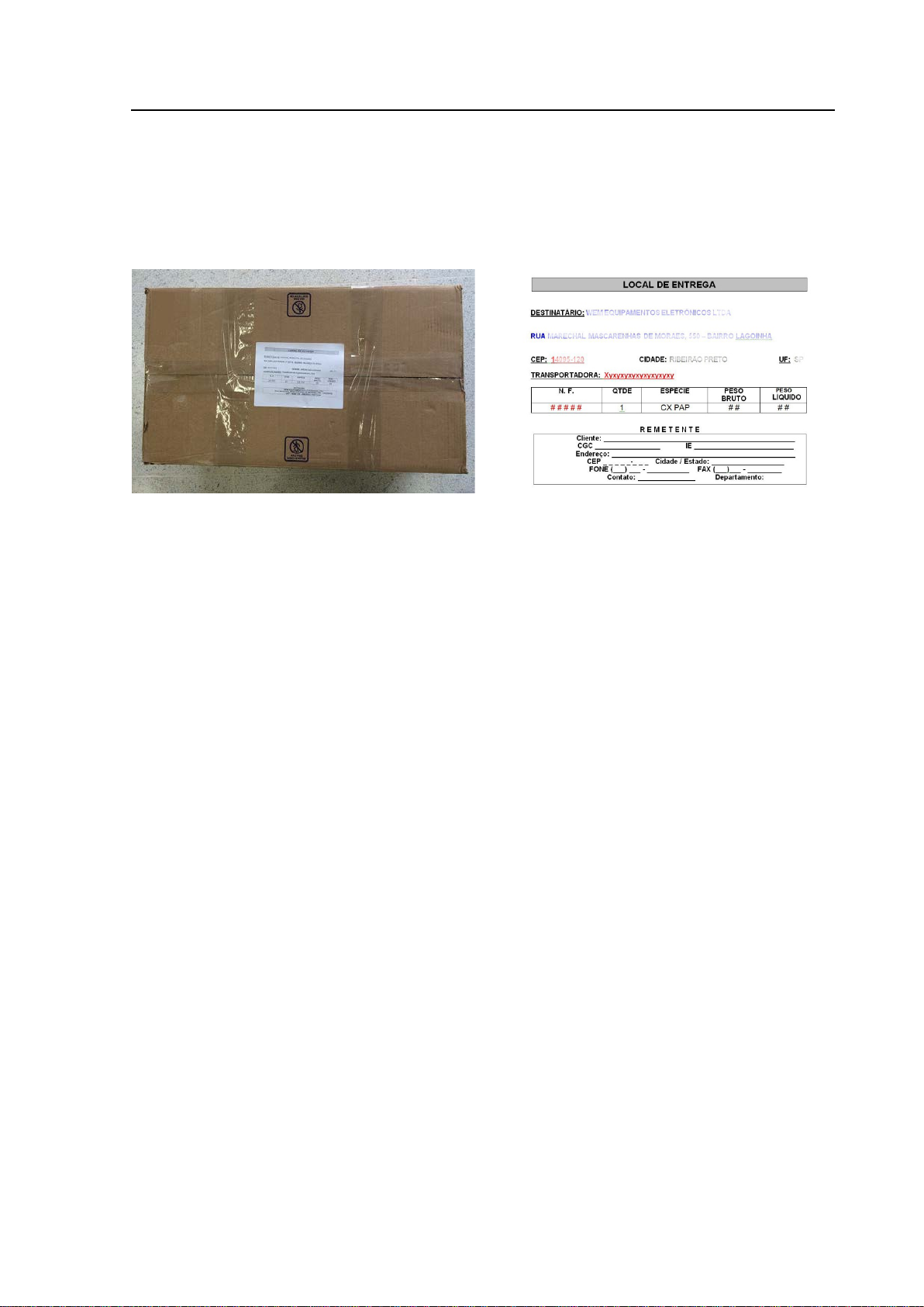
Etapa 4 – Utilize uma etiqueta adequada.
Para uma entrega rápida e eficiente, e para evitar transtornos nos serviços de assistência
técnica, tenha esses pontos em mente ao etiquetar um pacote:
- Inclua todos os dados do remetente, inclusive nome e telefone para contato;
- Coloque a etiqueta de remessa na parte superior do pacote. Sempre inclua seu endereço
completo para retorno.
1.7.3 Utilizando outros tipos de embalagens
Se a embalagem original não estiver disponível e for reutilizar uma caixa, certifique-se de que
a mesma esteja rígida e em excelentes condições, sem perfurações, rupturas, rasgos ou
danos nos cantos e que todas as abas estejam intactas. Remova todas as etiquetas e outras
marcas de remessas presentes.
Siga os passos abaixo:
Etapa 1 – Proteja o equipamento e os acessórios
a. Faça a correta higienização do produto e seus acessórios, utilizando o procedimento de
higienização interno da própria empresa;
b. Coloque o equipamento em uma sacola plástica ou envolva-o em plástico bolha;
c. Coloque os acessórios em uma outra sacola plástica.
Etapa 2 – Caixa de papelão
Utilize uma caixa de papelão ondulado, nova.
Caso utilize uma caixa usada, certifique-se de que a mesma tenha a resistência adequada
para fornecer proteção suficiente e esteja sem perfurações, rupturas, rasgos, danos nos
cantos e com todas as abas intactas.
Etapa 3 – Proteção interna
Faça uma camada de proteção apropriada no interior da caixa e acondicione o equipamento.
Complete a caixa com a proteção interna, acondicionando adequadamente os acessórios
entre o equipamento e as paredes da caixa, de forma a proteger completamente sua remessa.
Certifique-se de ter material de acondicionamento suficiente para garantir que o con teúdo não
se mova quando se balança a caixa.
⇒ O conteúdo deve ser posicionado pelo menos duas polegadas (50,8 mm) das paredes da
caixa, de acordo com a proteção interna utilizada. Isso evita danos entre produtos e protege
o conteúdo contra impactos e vibração que podem ser transmitidos do lado de fora da caixa
para o conteúdo.
⇒ “Bolinhas” de poliestileno expandido (material de enchimento solto) são para materiais
leves, portanto se utilizá-las, mantenha um espaçamento maior entre o conteúdo e as paredes
da caixa.
Página 1.12

Manual de Serviço SS-501LX / SX
Informações Gerais
⇒
Etapa 4 – Feche a caixa com segurança
O fechamento adequado da embalagem é tão importante quanto o enchimento apropriado
para a segurança de sua remessa. Use uma fita com duas polegadas (50,8 mm) ou mais de
largura.
IMPORTANTE: ver fotos do item 1.7.2, etapa 3, para referência.
Etapa 5 – Utilize uma etiqueta adequada
Para uma entrega rápida e eficiente, e para evitar transtornos nos serviços de assistência
técnica, tenha esses pontos em mente ao etiquetar um pacote:
- Inclua todos os dados do remetente, inclusive nome e telefone para contato;
- Coloque a etiqueta de r emessa na parte superior do pacote. Sempre inclua seu endereço
completo para retorno.
Página 1.13

Manual de Serviço SS-501LX / SX
Informações Técnicas
Informações Técnicas
CAPÍTULO 2
Esta seção introduz as informações técnicas sobre o produto e compatibilidades
aplicáveis, assim como informações para abertura do equipamento.
Página 2.1

Manual de Serviço SS-501LX / SX
Informações Técnicas
POTÊNCIA
MÁXIMA
CARGA
DECLARADA
Pure
300
Blend 1
250
Blend 2
200
Blend 3
150
Pure
300
500Ω
Blend
250
Blend 2
200
Blend 3
150
eCut 1
300
eCut 2
250
eCut 3
200
eCut 4
150
Fulgurate
120
Dessicate
180
Forced
120
Soft
120
100Ω
Bipolar
100
100Ω
Microbipolar
100
35Ω
Bipolar Cut
125
400Ω
Macrobipolar
125
200Ω
2.1 – ESPECIFICAÇÕES TÉCNICAS
Alimentação: 100-240V – 50/60 Hz – seleção automática de tensão
Corrente de Consumo: 6,9A (rede 127 VAC); 4,8A (rede 220 VAC)
Fusível de Entrada: 8A /250V (vidro, modelo 20AG, 20mm, rápido)
Potência Elétrica Máxima: 1000VA
Dimensões: 16,0 x 30,5 x 38,8 cm (alt x larg x prof)
Peso: 5,4 Kg (sem unidade de transporte)
Modo de Operação: Operação Intermitente
Proteção contra Choque
Elétrico: Equipamento de parte aplicada Tipo CF, Classe I
Frequência de operação: 390KHz
Regulação de base
(função ECUT): T
: 380ms a 1890ms, com padrão de 715ms e TON: 50ms
OFF
Alimentação pela Rede Elétrica:
Potência Nom. de Entrada: 38VA
Potência Mínima
Modo Stand By: 52VA (127V / 220V)
Potências Máximas
Corte (Puro): 1000VA
Coagulação: 600VA
Bipolar: 800VA
2.2 – SAÍDA DE POTÊNCIA EM CARGA D ECLARADA
2.2.1 SS-501LX
MODO FUNÇÃO
Corte
s/ High Cut
Corte
c/ High Cut
Monopolar
Corte
pulsado
Coagulação
Bipolar
Potência em Watts
300Ω
700Ω
200Ω
500Ω
Página 2.2

Manual de Serviço SS-501LX / SX
Informações Técnicas
POTÊNCIA
MÁXIMA
CARGA
DECLARADA
Pure
400
Blend 1
250
Blend 2
200
Blend 3
150
Pure
400
500Ω
Blend
250
Blend 2
200
Blend 3
150
eCut 1
400
eCut 2
250
eCut 3
200
eCut 4
150
Fulgurate
120
Dessicate
180
Forced
120
Soft
120
100Ω
Bipolar
200
100Ω
Microbipolar
100
35Ω
Bipolar Cut
250
400Ω
Macrobipolar
250
200Ω
2.2.2 SS-501SX
MODO FUNÇÃO
Monopolar
Bipolar
Potência em Watts
Corte
s/ High Cut
Corte
c/ High Cut
Corte
pulsado
Coagulação
300Ω
700Ω
200Ω
500Ω
Página 2.3

Manual de Serviço SS-501LX / SX
Informações Técnicas
Pure
c/ High Cut
Blend 1
c/ High Cut
Blend 2
c/ High Cut
Blend 3
c/ High Cut
Fulgurate
Desiccate
Micro
2.3 – CURVA DE POTÊNCIA x CARGA
Leituras efetuadas com display no valor máximo para todas as funções.
2.3.1 SS-501LX
Modo Monopolar
Função
Pure
Blend 1
Blend 2
Blend 3
Potência em watts
Função
Forced
Soft
Potência em watts
100Ω 300Ω 500Ω 700Ω 2000Ω
95 a 129 255 a 345 ---- ---- 61 a 83
97 a 131 213 a 288 ---- ---- 68 a 93
90 a 122 170 a 230 ---- ---- 60 a 82
83 a 112 128 a 173 ---- ---- 52 a 71
54 a 68
50 a 68
52 a 70 ---- ---- 170 a 230 89 a 120
53 a 71
----
---- ---- 213 a 288
---- ---- 128 a 173
255 a 345
----
174 a 236
106 a 143
72 a 98
50Ω 100Ω 500Ω 2000Ω
---- 94 a 127 103 a 139 91 a 123
---- 46 a 62 102 a 138 90 a 122
---- 63 a 86 153 a 207 92 a 124
63 a 85 102 a 138 --- 18 a 25
Modo Bipolar
Função
Cut
Macro
Bipolar
Potência em watts
25Ω 35 Ω 50Ω 100Ω 200Ω 400Ω 1000Ω
---- ---- ---- 28 a 38 ---- 106 a 144 56 a 76
---- ---- ---- 66 a 89 106 a 144 ---- 35 a 47
---- ---- 85 a 115 85 a 115 ---- ---- 19 a 26
62 a 83 85 a 115 ---- --- ---- ---- 12 a 16
Página 2.4

Manual de Serviço SS-501LX / SX
Informações Técnicas
Pure
c/ High Cut
Blend 1
c/ High Cut
Blend 2
c/ High Cut
Blend 3
c/ High Cut
Fulgurate
Desiccate
Macro
Micro
2.3.2 SS-501SX
Modo Monopolar
Função
Pure
Blend 1
Blend 2
Blend 3
Potência em watts
Função
Forced
Soft
Potência em watts
100Ω 300Ω 500Ω 700Ω 2000Ω
103 a 140 320 a 400 ---- ---- 72 a 97
97 a 130 213 a 288 ---- ---- 69 a 93
90 a 122 170 a 230 ---- ---- 60 a 82
82 a 112 128 a 173 ---- ---- 52 a 71
54 a 68
50 a 68
52 a 70 ---- ---- 170 a 230 88 a 120
53 a 71
---- 320 a 400 ----
---- ---- 213 a 288
---- ---- 128 a 173
174 a 236
106 a 143
72 a 98
50Ω 100Ω 500Ω 2000Ω
---- 94 a 127 102 a 138 91 a 123
---- 46 a 62 102 a 138 90 a 122
---- 63 a 86 153 a 207 92 a 124
63 a 85 102 a 138 --- 18 a 25
Modo Bipolar
Função
Cut
Bipolar
Potência em watts
25Ω 35 Ω 50Ω 100Ω 200Ω 400Ω 1000Ω
---- ---- ---- 61 a 82,5 ---- 212 a 287 112 a 153
---- ---- ---- 133 a 180 212 a 287 ---- 69 a 94
---- ---- 129 a 175 170 a 230 ---- ---- 35 a 47
61 a 83 85 a 115 ---- --- ---- ---- 12 a 16
Página 2.5

Manual de Serviço SS-501LX / SX
Informações Técnicas
Identificação
no display
Versão do
Produto
Teclas individuais para coagulação e bipolar;
- Falha: 90 a 100Ω.
Reconhecimento de PPM com:
- Falha: 135Ω.
Identificação
no display
Versão do
Produto
Função Bipolar com potência máxima de 100W;
- Falha: 90 a 100 Ω.
Função Bipolar com potência máxima de 200W;
- Falha: 90 a 100 Ω.
Reconhecimento de PPM com:
- Falha: 135 Ω.
Reconhecimento de PPM com:
- Falha: 90 a 100 Ω.
Reconhecimento de PPM com:
- Falha: 135 Ω.
Teclas individuais para coagulação e bipolar;
- Falha: 90 a 100Ω.
Reconhecimento de PPM com:
- Falha: 135Ω.
2.4 – VERSÃO DO SOFTWARE
Para verificar a versão do software no display: Ligue o equipamento e pressione as teclas UP
(↑) de Cut e DOWN (↓) de Bipolar.
Nota: Esta verificação é válida apenas na primeira vez que pressionar as teclas no painel.
2.4.1 SS-501LX
S.W.
LX_F.3.6 601 12a Update
LX_F.3.7 705 31a Update
Novas curvas de E-Cut;
Reconhecimento de PPM com:
- Lock: 80Ω.;
- Lock: 130Ω.;
Características
Nota: o Software LX_F3.6 não foi em equipamentos comercializados ao mercado.
2.4.2 SS-501SX
S.W.
F3.2 --- 2ª edição
F.3.5a 506 12a 2ª edição
F.3.5c 701 09a 2ª edição
Reconhecimento de PPM com:
- Lock: 80Ω.;
Reconhecimento de PPM com:
- Lock: 80Ω.;
- Lock: 130Ω;
Características
F.3.5b 506 12b 3ª edição
F.3.5d 701 09b 3ª edição
SX_F.3.6 601 12a Update
SX_F.3.7 705 31a Update
- Lock: 80Ω.;
- Lock: 130Ω;
Novas curvas de E-Cut;
Reconhecimento de PPM com:
- Lock: 80Ω.;
- Lock: 130Ω.;
Nota: o Software SX_F3.6 não foi em equipamentos comercializados ao mercado.
Página 2.6

Manual de Serviço SS-501LX / SX
Informações Técnicas
Placa MB
/ rev.
Placa CPU
/ rev.
NÚMERO DE SÉRIE
SS-501SX:
##### (5 dígitos) até CAB+7 dígitos
SS-501LX: LAC+7 dígitos
SS-501SX: CAC+7 dígitos
2.5 – PLACAS
Placa CPU: responsável por todo o controle do equipamento; localizam-se as memórias
de dados (CI-U10) e de calibração (CI-U8), o microcontrolador (CI-U11) e os
circuitos responsáveis pela seleção de modos e áudio, as teclas e os leds
indicadores;
Placa MB: responsável pela geração e controle de potência, assim como pelo
circuito de isolação entre as saídas de potência e circuitos
responsáveis pelos acionamentos; localizam-se os circuitos de
seleção automática de voltagem, inicialização, fonte chaveada de
potência, bloco de potênci a e circ ui to de isolação e saída.
Placa Input: possui os filtros de entrada de rede e fixação para o conec tor power module
(chave liga/desliga / fusíveis / conexão do cabo de alimentação).
2.6 – COMPATIBILIDADE DE PLACAS
A compatibilidade das placas CPU e MB SS-501Sx verifica-se pela revisão das mesmas.
Em caso de substituição, deve-se observar a compatibilidade indicada abaixo:
1
2
7 e 8 9 e 11
10 12
⇒ Notas:
1. Para identificação, ver a informação MB501SX REV # e CP501SX REV # onde # é a
revisão da pci.
2. A placa CPU possui código específico para cada versão de software (ver capítulo 6).
Página 2.7

Manual de Serviço SS-501LX / SX
Informações Técnicas
2.7 – CONEXÕES INTERNAS
Nota: Identificação dos conectores (figura c)
IDENTIFICAÇÃO DAS LIGAÇÕES INTERNAS
01 – Chicote n. 14 – BIPOLAR. Conectado em CN5/MB.
02 – Chicote n. 13 – PATIENT. Conectado em CN8/MB.
03 – Chicote n. 12 – MONOPOLAR 2. Conectado em CN7/MB.
04 – Chicote n. 11 – MONOPOLAR 1. Conectado em CN6/MB.
05 – Flat cable – chicote n. 10. Conectado entre CN3B/CPU e CN24/MB;
06 – Flat cable – chicote n. 09. Conectado entre CN3/CPU e CN23/MB;
07 – Chicote n. 02 – alimentação do circuito de inicialização. Conectado em CN3/MB;
08 – Chicote n. 01 – alimentação do circuito dobrador de tensão. Conectado em CN2/MB.
09 – Chicote n. 07 – alimentação da fonte chaveada - 340Vcc. Conectado em CN1/MB.
10 – Chicote n. 06 – conexão do pedal bipolar. Conectado em CN20/MB;
11 – Chicote n. 05 – conexão do pedal monopolar 2. Conectado em CN22/MB;
12 – Chicote n. 04 – conexão do pedal monopolar 1. Conectado em CN21/MB;
13 – Chicote n. 03 – terra de proteção. Conectado na lateral da base caixa;
Página 2.8

Manual de Serviço SS-501LX / SX
Informações Técnicas
2.8 – GUIA PARA DESMONTAGEM DO EQUIPAMENTO
Este guia tem como objetivo auxiliá-lo na desmontagem / montagem das partes do SS501SX. Para desmontagem da placa MB, não é necessário retirar o painel dianteiro, assim
como, para retirar a placa CPU, se faz necessário desmontar somente o painel dianteiro e não
as demais partes do equipamento.
2.8.1 - DESMONTAGEM DA TAMPA
Sequência:
a – Retire o lacre de segurança;
b – Retire os 04 parafusos que fixam a tampa;
c – Retire a tampa.
Página 2.9

Manual de Serviço SS-501LX / SX
Informações Técnicas
2.8.2 - DESMONTAGEM DO PAINEL TRASEIRO
Sequência:
a – Retire os 05 parafusos que fixam o painel traseiro
b – Retire o ‘chicote do terra de proteção’ da base caixa;
Desconecte os ‘chicotes dos pedais monopolar 1, monopolar 2 e bipolar’ de CN21,
CN22 e CN20, respectivamente;
Desconecte os ‘chicotes de alimentação’ de CN2 e CN3;
c – Desconecte o chicote do terra de proteção.
d – Recolocação do painel.
Página 2.10

Manual de Serviço SS-501LX / SX
Informações Técnicas
2.8.3 - DESMONTAGEM DO PAINEL DIANTEIRO
Sequência:
a – Retirar os 05 parafusos que fixam o painel dianteiro;
b – Desconecte todos os chicotes que fixam a placa CPU e a régua de bornes;
⇒ Nota: Para montagem do Painel Dianteiro, reportar-se à figura d e ao item 2.7 – Conexões
Internas.
Página 2.11

Manual de Serviço SS-501LX / SX
Informações Técnicas
2.8.4 - DESMONTAGEM DA PLACA MB
Sequência:
Para desmontagem dos painéis traseiro e dianteiro reporte-se aos itens 2.8.2 e 2.8.3.
a – Retire os 04 parafusos de fixação dos dissipadores da placa MB;
b – Desconecte todos os chicotes associados;
c, d – Desencaixe as 08 travas que prendem a placa MB.
Página 2.12

Manual de Serviço SS-501LX / SX
Rotina de Manutenção
Rotina de Manutenção
CAPÍTULO 3
Esta seção introduz informações para manutenção preventiva e corretiva do equipamento
descrito neste manual e apresenta as precauções associadas à reparação da unidade.
Normas de Segurança:
A não observância nas instruções contidas neste manual e no Manual de Utilização da
unidade relacionada poderá resultar em acidentes pessoais à equipe médica e ao
paciente.
Muitos dos riscos que dizem respeito à segurança estão relacionados à execução de
procedimentos de manutenção e reparo de forma inadequada.
Não execute nenhum serviço de manutenção, a não ser que:
- você tenha recebido treinamento técnico e esteja qualificado para trabalhar com esta
unidade;
- leia e siga as instruções contidas neste manual;
- siga as normas de segurança da empresa e os regulamentos do local de trabalho;
- você tenha as ferramentas e os equipamentos necessários e uma oficina apropriada.
Página 3.1

Manual de Serviço SS-501LX / SX
Rotina de Manutenção
⇒
3.1 – MANUTENÇÃO PREVENTIVA
Recomendamos que a manutenção preventiva seja realizada a cada 6 meses, por pessoal
técnico qualificado.
____________
⇒ NOTA
Realize esta inspeção para certificar-se de que o equipamento apresenta ou não alguma
irregularidade. O objetivo desta é verificar todo o funcionamento do equipamento.
Registre os resultados do teste para referência em manutenções futuras.
____________
EQUIPAMENTOS DE TESTE NECESSÁRIOS:
a – Analisador eletrocirúrgico, Fluke, modelo 454A com carga de até 2000Ω ou SPL
Elektronik, modelo HF-400;
b – Módulo PPM (0 a 200Ω);
c – Multímetro digital Fluke, modelo 115 – True RMS Multimeter, ou equivalente.
SEQUÊNCIA DE VERIFICAÇÃO:
1 – Faça uma inspeção visual na parte externa do equipamento:
Conjunto Caixa: Verifique estado geral (ex.: se não está amassada);
Painel Traseiro: Verifique chave liga-desliga, conectores dos pedais, porta-fusíveis e
fusíveis (conferir valores);
Painel Dianteiro: Verifique policarbonato, displays, teclas e conexões.
2 – Verifique se não há nada solto no interior do equipamento.
3 – Ligue o equipamento e cheque as condições gerais de funcionamento:
Verifique se todos os leds e displays acendem adequadamente;
Verifique o acionamento dos pedais (simples e duplo) e da caneta comando manual em
todas as saídas e tons de funcionamento;
Verifique as teclas e as condições do circuito de placa.
4 – Verificações internas:
Retire a tampa caixa;
Verifique a integridade das conexões internas;
Verifique se há resíduos de produtos de limpeza na placa e no interior do equipamento.
Se necessário, limpe a placa e/ou o interior do equipamento;
Verifique se todos os terminais e conectores estão em boas condições e com boa
pressão. Se necessário, substitua-os;
Recoloque a tampa caixa.
5 – Verifique potências do equipamento conforme item 2.3, deste manual;
Verifique linearidade em 20 e 50% da potência de saída máxima declarada, em todas
as funções.
6 – Meça a corrente de fuga de alta frequencia.
7 – Cheque a isolação entre saídas de potência.
8 – Cheque as condições do circuito automático de voltagem em 110Vca e em 220Vca.
DICA: meça a tensão nos pinos 3 e 4 do conector CN1 (placa MB).
9 – Inspecione todos os acessórios acompanhantes, inclusive cabo de força e cabo dos
pedais.
Página 3.2

Manual de Serviço SS-501LX / SX
Rotina de Manutenção
PROBLEMA
OBSERVAÇÕES
- atenção: Pare a cirurgia
Níveis mais baixos de potência reduzem a estimulação
elevados de voltagem envolvidos. A
dessecação não deve produzir estimulação neuromuscular,
pois não há faiscamento envolvido.
- Verifique se os fios terra do cabo de força dos equipamentos
1. A existência de faiscamento de metal para metal decorrente
que o corte. Níveis mais baixos de potência produzem menor
interferência.
- Verifique as conexões do cabo da placa e de acessórios. A
existência de faiscamento de metal para metal decorrente de
o mais próximo possível do local da cirurgia e faça com que o
do músculo cardíaco.
3.2 MANUTENÇÃO CORRETIVA
3.2.1 – PROBLEMAS QUE PODEM OCORRER DURANTE O PROCEDIMENTO
CIRÚRGICO
- Verifique todas as conexões dos acessórios e certifique-se
que não há mau-contato.
Estimulação
Neuromuscular
Interferência no monitor
cardíaco
Nota:
neuromuscular;
- A fulguração tende a produzir mais estimulação do que o corte
devido a níveis mais
envolvidos não estão interrompidos;
- Verifique a integridade da conexão chassis-terra do SS-501LX
/ SS-501SX, gerador, e do monitor;
- Verifique se o circuito d e aterramento da instalação elétrica da
sala cirúrgica está adequado;
- Verifique as conexões do cabo da placa e de acessórios.
Notas:
de mau-contato das conexões pode causar interferência;
2. A fulguração tende a produzir maior nível de interferência do
mau-contato das conexões pode causar interferência;
Interferência em
Marcapasso
- Dê preferência à utilização de instrumentos bipolares;
- Quando for utilizar instrumentos monopolares, coloque a placa
caminho percorrido pela corrente fique o mais afastado possível
Página 3.3

Manual de Serviço SS-501LX / SX
Rotina de Manutenção
Códigos
de Erros
Função
Relacionada
Desligue e ligue novamente o aparelho sem os acessórios
sistema de Auto Teste, contate a assistência técnica.
Desligue e ligue novamente o aparelho sem pressionar a
defeito, contate a assistência técnica autorizada.
Desligue e ligue novamente o aparelho sem pressionar a
defeito, contate a assistência técnica autorizada.
Mais de uma
e
Desligue e ligue novamente o aparelho sem pressionar a
defeito, contate a assistência técnica autorizada.
Desligue e ligue novamente o aparelho sem pressionar a
defeito, contate a assistência técnica autorizada.
Valores
Calibração
Desligue e ligue novamente o aparelho sem os acessórios
sistema de Auto Teste, contate a assistência técnica.
Desligue e ligue o aparelho novamente sem pressionar as
técnica autorizada.
Desligue e ligue o aparelho novamente sem pressionar a
assistência técnica autorizada.
Desligue e ligue o aparelho novamente sem pressionar os
técnica autorizada.
3.3 SELF TESTE
Ao ligar o equipamento se realiza um Auto Teste e apresenta um código de erro no display
para determinadas situações de falha, conforme tabela a seguir:
Falha
16 Sistema Auto Teste
17
18
19 a 31
20
Tecla
ativada
direto
Tecla
ativada
direto
Tecla
ativada
direto
Tecla
ativada
direto
Seleção de
modos
Controle
Up/Down
tecla do painel
ativada
simultaneament
MEMORY
Descrição
conectados.
Caso a mensagem de erro não desaparecer defeito no
tecla no painel (HIGH CUT, PURE, BLEND1, BLEND2,
BLEND3, FULGURATE, DESICCATE, BIPOLAR e MICRO).
Caso a mensagem de erro não desaparecer a tecla está com
tecla no painel UP e DOWN para os menus de: Cut, Coag,
Bipolar e Volume.
Caso a mensagem de erro não desaparecer a tecla está com
Desligue e ligue novamente o aparelho sem pressionar
teclas no painel.
Caso a mensagem de erro não desaparecer as teclas estão
com defeito, contate a assistência técnica autorizada.
tecla no painel (SAVE, LOAD e REMOTE).
Caso a mensagem de erro não desaparecer a tecla está com
Tecla
24
64 a 79
80 Sistema Auto Teste
81
82
83
ativada
direto
Memória
EEPROM
Acionado
direto
BIPOLAR
acionado
direto
Acionado
direto
Função eCUT e
STAND BY
Displays e
Pedais
acionados
simultaneament
e
Pedal Bipolar
Canetas
acionadas
simultaneament
e
tecla no painel (eCUT e STAND BY).
Caso a mensagem de erro não desaparecer a tecla está com
Memória EEPROM com defeito contate a assistência técnica
autorizada.
conectados.
Caso a mensagem de erro não desaparecer defeito no
alavancas interruptoras dos pedais.
Caso a mensagem de erro não desaparecer depois de liberar
os interruptores dos pedais, desconectar os pedais no painel
traseiro, caso o problema persistir contate a assistência
alavanca interruptora CUT do pedal bipolar.
Caso a mensagem de erro não desaparecer depois de liberar
o interruptor CUT do pedal BIPOLAR, tente desconectar o
pedal no painel traseiro, caso o problema persistir contate a
botões interruptores das canetas.
Caso a mensagem de erro não desaparecer depois de liberar
os botões das canetas, tente desconectar as canetas no
painel frontal, caso o problema persistir contate a assistência
Página 3.4

Manual de Serviço SS-501LX / SX
Rotina de Manutenção
Desligue e ligue o aparelho novamente sem pressionar os
técnica autorizada.
Desligue e ligue o aparelho novamente sem pressionar os
técnica autorizada.
Desligue e ligue o aparelho novamente sem pressionar a
assistência técnica autorizada.
Desligue e ligue o aparelho novamente sem pressionar a
assistência técnica autorizada.
Desligue e ligue o aparelho novamente sem pressionar a
assistência técnica autorizada.
Desligue e ligue o aparelho novamente sem pressionar a
assistência técnica autorizada.
Desligue e ligue o aparelho novamente sem pressionar a
assistência técnica autorizada.
Desligue e ligue o aparelho novamente sem pressionar o
técnica autorizada.
Desligue e ligue o aparelho novamente sem pressionar o
técnica autorizada.
Desligue e ligue o aparelho novamente sem pressionar o
técnica autorizada.
botões interruptores da caneta monopolar1.
84
85
Acionado
direto
Acionado
direto
Caneta
Monopolar1
Caneta
Monopolar2
Caso a mensagem de erro não desaparecer depois de liberar
o botão da caneta, tente desconectar as canetas no painel
frontal, caso o problema persistir contate a assistência
botões da caneta monopolar2.
Caso a mensagem de erro não desaparecer depois de liberar
o botão da caneta, tente desconectar as canetas no painel
frontal, caso o problema persistir contate a assistência
86
87
88
89
90
CUT
acionado
direto
CUT
acionado
direto
COAG
Acionado
direto
COAG
acionado
direto
BIPOLAR
acionado
direto
Pedal
Monopolar1
Pedal
Monopolar2
Pedal
Monopolar1
Pedal
Monopolar2
Pedal Bipolar
alavanca interruptora CUT do pedal monopolar1.
Caso a mensagem de erro não desaparecer depois de liberar
o interruptor CUT do pedal, tente desconectar o pedal no
painel traseiro, caso o problema persistir contate a
alavanca interruptora CUT do pedal monopolar2.
Caso a mensagem de erro não desaparecer depois de liberar
o interruptor CUT do pedal, tente desconectar o pedal no
painel traseiro, caso o problema persistir contate a
alavanca interruptora COAG do pedal monopolar1.
Caso a mensagem de erro não desaparecer depois de liberar
o interruptor COAG do pedal, tente desconectar o pedal no
painel traseiro, caso o problema persistir contate a
alavanca interruptora COAG do pedal monopolar2.
Caso a mensagem de erro não desaparecer depois de liberar
o interruptor COAG do pedal, tente desconectar o pedal no
painel traseiro, caso o problema persistir contate a
alavanca interruptora COAG do pedal bipolar.
Caso a mensagem de erro não desaparecer depois de liberar
o interruptor COAG do pedal BIPOLAR, tente desconectar o
pedal no painel traseiro, caso o problema persistir contate a
CUT
91
92
93
acionado
direto
CUT
acionado
direto
COAG
acionado
direto
Caneta
Monopolar1
Caneta
Monopolar2
Caneta
Monopolar1
botão interruptor CUT da caneta monopolar1.
Caso a mensagem de erro não desaparecer depois de liberar
o botão CUT da caneta, tente desconectar a caneta no painel
frontal, caso o problema persistir contate a assistência
botão interruptor CUT da caneta monopolar2.
Caso a mensagem de erro não desaparecer depois de liberar
o botão CUT da caneta, tente desconectar a caneta no painel
frontal, caso o problema persistir contate a assistência
botão interruptor COAG da caneta monopolar1.
Caso a mensagem de erro não desaparecer depois de liberar
o botão COAG da caneta, tente desconectar a caneta no
painel frontal, caso o problema persistir contate a assistência
Página 3.5

Manual de Serviço SS-501LX / SX
Rotina de Manutenção
Desligue e ligue o aparelho novamente sem pressionar o
técnica autorizada.
Desligue e ligue o aparelho novamente sem pressionar as
técnica autorizada.
Desligue e ligue novamente o aparelho sem os acessórios
sistema de Auto Teste, contate a assistência técnica.
Desligue e ligue novamente o aparelho sem os acessórios
autorizada.
Desligue e ligue novamente o aparelho sem os acessórios
autorizada.
Desligue e ligue novamente o aparelho sem os acessórios
assistência técnica autorizada.
Desligue e ligue novamente o aparelho sem os acessórios
técnica autorizada.
Desligue e ligue novamente o aparelho sem os acessórios
autorizada.
Desligue e ligue novamente o aparelho sem os acessórios
assistência técnica autorizada.
Desligue e ligue novamente o aparelho sem os acessórios
autorizada.
COAG
94
95
128 Sistema Auto Teste
129
130
acionado
direto
BIPOLAR
acionado
direto
Potência
de RF
incorreta
Potência
de RF
incorreta
Caneta
Monopolar2
Pedal Bipolar
Falha no
controle de
Potência
Falha no
controle de
Potência para
cargas baixas
botão interruptor COAG da caneta monopolar2.
Caso a mensagem de erro não desaparecer depois de liberar
o botão COAG da caneta, tente desconectar a caneta no
painel frontal, caso o problema persistir contate a assistência
alavancas do pedal bipolar.
Caso a mensagem de erro não desaparecer depois de liberar
o pedal BIPOLAR, tente desconectar o pedal no painel
traseiro, caso o problema persistir contate a assistência
conectados.
Caso a mensagem de erro não desaparecer defeito no
conectados.
Caso a mensagem de erro não desaparecer foi detectado
falha no circuito de sensor de tensão durante o teste de
automático de potência, contate a assistência técnica
conectados.
Caso a mensagem de erro não desaparecer foi detectado
falha no circuito de sensor de corrente durante o teste de
automático de potência, contate a assistência técnica
131 a 254
132
136
144
145
Potência
de RF
incorreta
Potência
de RF
incorreta
Potência
RF
incorreta
Potência
RF
incorreta
Potência
RF
incorreta
Falha no
controle de
Potência
Falha no
controle
Potência aberto
ou cargas altas
Falha no
controle
corrente de fuga
Falha no
controle de
potência
redundante
Falha no
controle de
potência
conectados.
Caso a mensagem de erro não desaparecer foi detectado
múltiplos problemas no controle de potência, contate a
conectados.
Caso a mensagem de erro não desaparecer foi detectado
falha no circuito de sensor de corrente de fuga durante o
teste de automático de potência, contate a assistência
conectados.
Caso a mensagem de erro não desaparecer foi detectado
falha no circuito de sensor de carga durante o teste de
automático de potência, contate a assistência técnica
conectados.
Caso a mensagem de erro não desaparecer o fornecimento
de potência interna atingiu um valor de potência acima do
especificado e foi totalmente interrompido, contate a
conectados.
Caso a mensagem de erro não desaparecer o fornecimento
de potência interna atingiu uma condição de sobre potência e
foi totalmente interrompido, contate a assistência técnica
Página 3.6

Manual de Serviço SS-501LX / SX
Rotina de Manutenção
Desligue e ligue novamente o aparelho sem os acessórios
autorizada.
Desligue e ligue novamente o aparelho sem os acessórios
a assistência técnica autorizada.
Desligue e ligue novamente o aparelho sem os acessórios
PURE, contate a assistência técnica autorizada.
Desligue e ligue novamente o aparelho sem os acessórios
autorizada.
Desligue e ligue novamente o aparelho sem os acessórios
técnica autorizada.
160
162
192
226
255
Potência
RF
incorreta
Potência
RF
incorreta
Potência
RF
incorreta
Potência
RF
incorreta
Potência
RF
incorreta
Falha no
controle de
Potência
redundante para
cargas baixas
Falha no
controle de
Potência para
cargas baixas
Falha no
controle de
potência
Falha no
controle de
potência
Módulo de
potência
conectados.
Caso a mensagem de erro não desaparecer foi detectado
falha no circuito de sensor curto durante o teste de
automático de potência, contate a assistência técnica
conectados.
Caso a mensagem de erro não desaparecer o fornecimento
de potência para cargas baixas atingiu um valor de potência
acima do especificado e foi totalmente interrompido, contate
conectados.
Caso a mensagem de erro não desaparecer foi detectado
defeito no circuito de compensação de potência do modo HI
conectados.
Caso a mensagem de erro não desaparecer foi detectado
falha no sensor de corrente, contate a assistência técnica
conectados.
Caso a mensagem de erro não desaparecer foi detectado
falha nas conexões de CN1 e CN2, contate a assistência
Página 3.7

Manual de Serviço SS-501LX / SX
Esquemas Elétricos
Esquemas Elétricos
CAPÍTULO 4
Esta seção apresenta os esquemas elétricos relacionados à manutenção das principais
falhas do equipamento.
Página 4.1

Manual de Serviço SS-501LX / SX
Esquemas Elétricos
4.1 – ESQUEMAS ELÉTRICOS
4.1.1 – PLACA CPU
a) Alimentação
b) Conexões Placas CPU / MB
Página 4.2

Manual de Serviço SS-501LX / SX
Esquemas Elétricos
4.1.2 – PLACA MB
a) Alimentação
b) Circuito de Isolação e Saída
Página 4.3

Manual de Serviço SS-501LX / SX
Esquemas Elétricos
c) Circuito de Acionamento Pedal
Página 4.4

Manual de Serviço SS-501LX / SX
Calibração e Ajuste
Calibração e Ajuste
CAPÍTULO 5
Esta seção introduz informações para calibração do bisturi, modelo SS-501LX / SS-
501SX, assim como as ferramentas necessárias para esta atividade.
Terminologia
Calibração:
“Operação que estabelece, numa primeira etapa e sob condições especificadas, uma relação entre os valores
e as incertezas associadas; numa segunda etapa, utiliza esta informação para estabelecer uma relação
visando a obtenção de um resultado de medição a partir de uma indicação.” (VIM2.39, 2008)
Ajuste:
“Conjunto de operações efetuadas em um sistema de medição, de modo que ele forneça indicações prescritas
correspondentes a determinad os valor es de uma grand ez a a ser medida.” (VIM 3.11, 2008)
Em resumo:
Calibração refere-se ao ato de comparar as leituras da Unidade Sob Teste com valores estabelecidos, ao
passo que Ajuste refere-se ao ato de proceder a manutenção do equipamento, até que este volte a medir
dentro dos parâmetros estabelecidos pelo fabricante.
NOTA: O ajuste de um sistema não deve ser confundido com a calibração, a qual é um pré-requisito para o
ajuste.
Normas de Segurança:
Não execute nenhum serviço de calibração, a não ser que:
- tenha recebido treinamento técnico e esteja qualificado para trabalhar com esta unidade;
- leia e siga as instruções contidas nesta seção;
- siga as normas de segurança da empresa e os regulamentos do local de trabalho;
- tenha as ferramentas e os equipamentos necessários e uma oficina apropriada.
Página 5.1

Manual de Serviço SS-501LX / SX
Calibração e Ajuste
⇒
5.1 CAL IBRAÇÃO E AJUSTE
____________
NOTA
Antes de iniciar a calibração, certifique-se de que a versão do software é a mesma deste
procedimento. Em caso de dúvidas consulte o item 2.7 – Versão de Software, neste manual
de serviços.
____________
INSTRUMENTOS UTILIZADOS
• Analisador eletrocirúrgico, Fluke, modelo 454A com carga selecionável de até 2000Ω
ou SPL Elektronik, modelo HF-400;
• Multímetro digital Fluke, modelo 115 – True RMS Multimeter, ou equivalente.
• Acessórios do bisturi (placa terra, caneta de comando manual e/ou de comando por
pedal, pinça bipolar, pedal duplo e/ou pedal simples);
• Módulo PPM (0 a 200Ω);
5.1.1 VERIFICAÇÕES DE POTÊNCIA E DO CIRCUITO DE PLACA
VERIFICAÇÃO DO CIRCUITO PPM / PLC
____________
CIRCUITO PLC / PPM
PLC – utilização da placa única
PPM – utilização da placa dividida
Para verificação e/ou calibração, será necessário o Teste PPM especificado acima.
____________
01. Verifique o circuito PPM/PLC.
VERIFICAÇÃO DE POTÊNCIA
01. Verifique as saídas de potência em todas as funções dos modos Monopolar e Bipolar, nas
saídas Monopolar 1, Monopolar 2 e Bipolar.
02. Verifique as correntes de fuga de alta frequência.
03. Verifique a isolação entre as saídas de potência.
Página 5.2

Manual de Serviço SS-501LX / SX
Partes e Peças
Partes e Peças
CAPÍTULO 6
Esta seção apresenta as principais partes do bisturi eletrônico microprocessado, modelos
SS-501LX e SS-501SX e a lista de peças de reposição sugerida pela WEM para que se
A utilização de peças e partes não originais ou indicadas pela fábrica poderá colocar em
risco a qualidade dos serviços realizados e a segurança do equipamento e do paciente.
tenha em estoque para uma rápida e efetiva manutenção.
Normas de Segurança:
Página 6.1

Manual de Serviço SS-501LX / SX
Partes e Peças
ITEM
DESCRIÇÃO
PAINEL DIANTEIRO SS-501LX – UP
PAINEL DIANTEIRO SS-501SX - UP
PCI CPU SS-501LX REV.12 (SW F3.7)
PCI CPU SS-501SX REV.12 (SW F3.7)
PAINEL TRASEIRO SS-501LX UP
PAINEL TRASEIRO SS-501SX UP
6.1 – PARTES E PEÇAS
6.1.1 – VISTA EXPLODIDA
IDENTIFICAÇÃO DAS PARTES:
01
02
03 PCI MB SS-501SX REV.10 (MONTADA) (INSPECIONADA)
04 CONJ. CAIXA SS-501SX UP
05 M 3 X 8 - PAR.CHATA PHILIPS INOX 304 (BELLENUS)
06
Página 6.2

Manual de Serviço SS-501LX / SX
Partes e Peças
Painéis policarbonato inclusos.
Sem placa CPU.
Software Gravado. Com flat cables
inclusos.
6.1.2 – PAINEL DIANTEIRO
6.1.2.1 – PAINEL DIANTEIRO SS-501LX
PAINEL DIANTEIRO SS-501LX - UP PCI CPU SS-501LX REV.12 (SW F3.7)
PAINEL POLIC. SS-501LX DIANTEIRO
Nota: O painel policarbonato bornes não é vendido separadamente.
Página 6.3

Manual de Serviço SS-501LX / SX
Partes e Peças
Painéis policarbonato inclusos.
Sem placa CPU.
6.1.2.2 – PAINEL DIANTEIRO SS-501SX
PAINEL DIANTEIRO SS-501SX - UP PCI CPU SS-501SX REV.12 (SW F3.7)
Software gravado. Com flat cables inclusos.
PAINEL POLIC. SS-501SX DIANTEIRO
Nota: O painel policarbonato bornes não é vendido separadamente.
Página 6.4
Manual de Serviço SS-501LX / SX
Partes e Peças
ITEM
DESCRIÇÃO
PAINEL TRASEIRO SS-501LX UP
PAINEL TRASEIRO SS-501SX UP
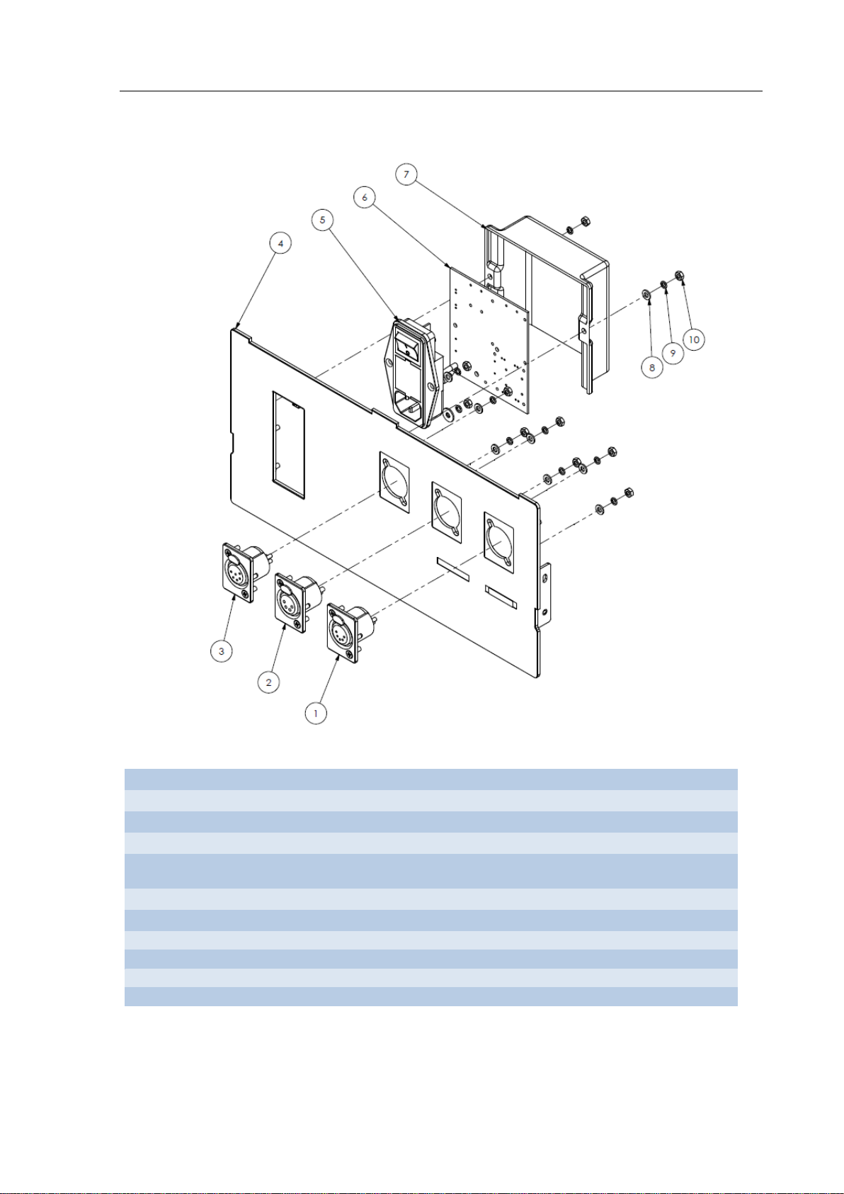
07
PROTECAO PAINEL TRAS.UNIF. 6980 (USINADO)
08
ARRUELA LISA 1/8" ZINCADA (D.E. 9/10MM) DIN 994
09
ARRUELA PRESSAO 1/8" ZINC./ ACO SAE 1060
10
M 3 - PORCA TORNEADA ZINC./ ACO SAE 1010/1020
6.1.3 – VISTA EXPLODIDA – PAINEL TRASEIRO SS-501LX / SS-501SX
IDENTIFICAÇÃO DAS PARTES:
01 CONECTOR XLR FEMEA - 5 VIAS - NC5FP1 (NEUTRIK) (METALICO)
02 CONECTOR XLR FEMEA - 4 VIAS - NC4FP1 (NEUTRIK) (METAL)
03 CONECTOR XLR FEMEA - 6 VIAS - NC6FP1 (NEUTRIK) (METAL)
04
05 CONECTOR POWER DPST - 76400/002 (QUALTEK)
06 PCI INPUTAC SS-501SX (MONTADA) (LM/ 10034 REV.01)
Página 6.5

Manual de Serviço SS-501LX / SX
Apêndice
Apêndice
Esta seção apresenta informações complementares ao manual de serviço.
Página A1

Manual de Serviço SS-501LX / SX
Apêndice
GARANTIA
O equipamento sai de fábrica testado e calibrado tendo garantia contra defeitos de fabricação.
A garantia limita-se à mão-de-obra e reposição de peças defeituosas. A abertura do
equipamento por oficina ou pessoa não autorizada, dentro do prazo de garantia, acarreta a
perda da mesma.
TRANSPORTE / FRETE
As despesas de frete e seguro correm por conta do cliente, ou da oficina autorizada que esteja
enviando o equipamento para o centro de serviço WEM.
PRAZO DE GARANTIA
Unidade eletrocirúrgica 12 meses
Unidade de Transporte (opcional) 12 meses
Pedal 12 meses
Demais Acessórios – a garantia é definida pela média de vida útil (conforme abaixo) ou 90
dias, o que vencer primeiro:
- Caneta c/ comando manual: 3 meses ou 40 utilizações;
- Caneta c/ comando no pedal: 3 meses ou 50 utilizações;
- Cabo de silicone para caneta comando por pedal: 3 meses ou 40 utilizações;
- Eletrodos de todos os tipos: 3 meses ou 50 utilizações;
- Pinça bipolar e monopolar: 3 meses ou 50 utilizações.
⇒ Nota: Excluem-se das informações acima, os acessórios descartáveis.
ESTERILIZAÇÃO DE ACESSÓRIOS
AUTOCLAVAGEM A VAPOR:
Informamos que as canetas reusáveis e todas as pinças monopolares e bipolares, assim como
todos os eletrodos de fabricação WEM, são autoclaváveis em temperaturas de até 134ºC.
⇒ Vale ressaltar que o número de esterilizações pode variar de acordo com o processo.
NOTA:
Ver item Esterilização de Acessórios no manual de utilização do produto, para maiores
informações e outros modos de limpeza.
VIDA ÚTIL:
A esterilização por óxido de etileno (ETO) ou peróxido de hidrogênio (nome comercial
“STERRAD” – da Johnson & Johnson) aumenta a v ida útil de todos os n ossos ace ssórios, em
relação à esterilização por autoclavagem à vapor ou qualquer outro processo de esterilização.
⇒ Não recomendamos a esterilização por agentes germicidas, como, por exemplo, solução a
base de GLUTARALDEÍDO, pois seu teor é altamente corrosivo e poderá danificar os
acessórios confeccionados a base de aço inoxidável e silicone.
Página A2

Manual de Serviço SS-501LX / SX
Apêndice
DADOS DA EMPRESA
Empresa:
Contato:
Telefone:
e-mail:
DADOS DO PRODUTO
Modelo do equipamento:
Número de Sér ie:
Data de Fabricação:
Garantia: □ sim □ não
Versão de Software:
Cliente Final (Hospital):
RECLAMAÇÃO TÉCNICA
Descrição da Falha:
Data da Identificação:
Local de Identificação:
Reincidência: □ sim □ não
Em caso de reincidência da falha, informar se está utilizando componentes fornecidos pela
WEM ou não.
SUPORTE TÉCNICO
Ao entrar em contato com a fábrica para serviços de suporte técnico sempre tenha em mãos
as informações abaixo, a fim de agilizar o processo.
Informações Pertinentes:
– Como ocorreu a falha?
– Função e valor potência utilizada durante a percepção da falha
– A função utilizada era pertinente para o procedimento em questão?
– Em que procedimento estava sendo utilizado o equipamento?
– Qual a duração padrão do procedimento?
– Após quanto tempo de uso ocorreu a falha?
– Se a falha estiver relacionada a performance do equipamento, informe se a mesma ocorre
em todos os procedimentos ou somente em um procedimento específico.
– A f alha foi percebida por vários cirurgiões ou somente um? Se somente um, informe se o
equipamento é utilizado por outras equipes.
– Tensão da rede elétrica;
– Que acessórios estavam sendo utilizados e qual a marca dos mesmos?
– Já experimentou utilizar outro acessório comprovadamente sem defeito?
Página A3

Service Manual
Microprocessed Electrosurgical
Generator
Models
SS-501LX & SS-501SX

Service Manual (hosp) revision: 00
Reference: 06_tri
Edition: June / 2017
Service Manual
Microprocessed Electrosurgical Generator
Models
SS-501LX & SS-501SX
technical assistance contact
Auto Suture do Brasil LTDA
Praça Agrícola La Paz Tristante, 131, setor 1, parte 8
Parque Industrial Anhanguera, Osasco | São Paulo, Brazil, Postal Code: 06276-035
0800 179 944
e-mail: suporte@covidien.com

SS-501LX

Postal Code 14095-120
SS-501SX
Manufacturer:
WEM Equipamentos Eletrônicos Ltda.
[Corporate Taxpayer Registry] CGC no. 54 611 678/0001-30
[street] Rua Marechal Mascarenhas de Moraes, 550
[city] Ribeirão Preto - SP - Brazil

SS-501LX / SX Service Manual
Table of Content
SUBJECT
PAGE
CHAPTER 1 – GENERAL INFORMATION
1.1 Introduction ----------------------------------------------------------------------------------------------------
1.2
1.2 General Features ---------------------------------------------------------------------------------------------
1.3
1.3 Applications ----------------------------------------------------------------------------------------------------
1.3
1.4 Simultaneous Output ----------------------------------------------------------------------------------------
1.3
1.5 Physical Principle and Fundam entals of Equipment Technology Applied to its Operati on
and Action -----------------------------------------------------------------------------------------------------------
1.6 Installation Instructions --------------------------------------------------------------------------------------
1.6
1.7 Packaging Process for Shipment ------------------------------------------------------------------------
1.10
CHAPTER 2 – TECHNICAL INFORMATION
2.1 Technical Specifications ------------------------------------------------------------------------------------
2.2
2.2 Output Power in a Rated Load ----------------------------------------------------------------------------
2.2
2.2.1 SS-501LX ----------------------------------------------------------------------------------------------
2.2
2.2.2 SS-501SX ---------------------------------------------------------------------------------------------
2.3
2.3 Load Response Curve --------------------------------------------------------------------------------------
2.4
2.3.1 SS-501LX ----------------------------------------------------------------------------------------------
2.4
2.3.2 SS-501SX ----------------------------------------------------------------------------------------------
2.5
2.4 Software Versions --------------------------------------------------------------------------------------------
2.6
2.4.1 SS-501LX ----------------------------------------------------------------------------------------------
2.6
2.4.2 SS-501SX ----------------------------------------------------------------------------------------------
2.6
2.5 Boards -----------------------------------------------------------------------------------------------------------
2.7
2.6 Compatibility of Boards -------------------------------------------------------------------------------------
2.7
2.7 Internal Connections -----------------------------------------------------------------------------------------
2.8
2.8 Disassembling Guide of the Equipment ----------------------------------------------------------------
2.9
2.8.1 Disassembling of the Top Case ------------------------------------------------------------------
2.9
2.8.2 Disassembling of the Rear Panel ----------------------------------------------------------------
2.10
2.8.3 Disassembling of the Front Panel ----------------------------------------------------------------
2.11
2.8.4 Disassembling of the MB board ------------------------------------------------------------------
2.12
CHAPTER 3 – MAINTENANCE ROUTINE
3.1 Preventive Maintenance ------------------------------------------------------------------------------------
3.2
3.2 Corrective Maintenance ------------------------------------------------------------------------------------
3.3
3.2.1 Problems that May Occur During the Surgical Procedure ---------------------------------
3.6
3.4 Self-Test --------------------------------------------------------------------------------------------------------
3.7
CHAPTER 4 – SCHEMATIC DIAGRAM
4.1 Schematic Diagrams ----------------------------------------------------------------------------------------
4.2
4.1.1 CPU board ---------------------------------------------------------------------------------------------
4.2
4.1.2 MB board -----------------------------------------------------------------------------------------------
4.3
5.1 Calibration and Adjust ---------------------------------------------------------------------------------------
5.2
5.1.1 Checking of the Output Power and Patient Plate Circuit -----------------------------------
5.2
6.1 Parts and Spares ---------------------------------------------------------------------------------------------
6.2
6.1.1 Exploded View ----------------------------------------------------------------------------------------
6.2
6.1.2 Front Panel ---------------------------------------------------------------------------------------------
6.3
6.1.2.1 – SS-501LX Front Panel -------------------------------------------------------------------
6.3
6.1.2.2 – SS-501SX Front Panel ------------------------------------------------------------------
6.4
6.1.3 Exploded View – SS-501LX / SX Rear Panel -------------------------------------------------
6.5
Warranty ---------------------------------------------------------------------------------------------------------------
A2
Accessory Sterilization ---------------------------------------------------------------------------------------------
A2
Technical Support ---------------------------------------------------------------------------------------------------
A3
TABLE OF CONTENT
1.4
CHAPTER 5 – CALIBRATION AND ADJUST
CHAPTER 6 – PARTS AND SPARES
APPENDIX

SS-501LX / SX Service Manual
General Information
General Information
CHAPTER 1
For more safety:
a) Read and understand all instructions contained in the Operational Manual before
installing or operating these equipment.
b) This Service Manual must be used by engineers a nd technicians with the purpose
of performing technical servicing in WEM equipment, model SS-501LX / SS501SX.
ATTENTION
This manual was originally written in Portuguese language.
Page 1.1

SS-501LX / SX Service Manual
General Information
1.1 – INTRODUCTION
The following service instructions are for use only by qualified personnel to installation
and maintenance of the electrosurgical unit described in this manual. WEM will not be
responsible for an improper us e of the information contained here.
The purpose of this manual is to provide information about installation and maintenance
of the SS-501LX / SS-501SX, such as technical information, maintenance routine and criterion
of acceptance for calibration and adjust, besides others.
WEM reserves the right to make changes in this manual or on the equipment without
advance notice.
All rights reserved. Contents of this manual should not be reproduced in any form w ithout
the written permission of WEM Equipamentos Eletrônicos Ltda.
⇒ ATTENTION: Before starting the maintenance service, read the correspondent Operation
Manual carefully for a thorough understanding of operation and principles of electrosurgery.
Service Manual – revision 1
The model SS-501LX was included in this revision of the servisse manual.
Features of the SS-501SX in relation to the servisse manual revision 0:
- Excluded the ALT key;
- The coagulation and bipolar functions were separated for individual keys for each
function.
- The accessories connections on front panel were changed to universal standard.
# Identification of the software version and serial number involved. #
This manual was developed in accordance with the software versions ‘SS_501LX_F.3.7’ /
‘SS_501SX_F.3.7’ and attends to the serial numbers:
SS-501LX: ‘LAC + 7 digits’.
SS-501SX: ‘CAC + 7 digits’.
For previous or later versions of the software, consult the correspondent service manual in
order to check if it is appropriate for the servicing to be performed.
Complementary Information:
IDENTIFICATION OF THE 2nd AND 3rd EDITION OF NBR IEC 60.601-1 STANDARD
The identification is done by the serial number, as follows:
NBR IEC 60.601.1 2nd edition
Until approximately December 2015, WEM used 5 numeric digits for serial number. After that,
WEM started using 3 letters and 7 numeric digits. In 2
nd
edition this new identification of the
equipment SS-501SX is done by the serial number ‘CAA + 7 digits’.
NBR IEC 60.601.1 3rd edition
The identification of equipment SS-501SX under 3rd edition is done from the serial number
‘CAB + 7 digits’.
Page 1.2

SS-501LX / SX Service Manual
General Information
1
FULGURATE
FULGURATE
-----------
1.2 – GENERAL FEATURES
Features
- Fully microprocessed;
- 12 cutting functions: pure, blend 1, 2 and 3 (with and without High Cut), Ecut 1, 2,
3 and 4;
- 4 coagulation functions: fulgurate, forced, desiccate and soft, which allows the
adjustment of the effect and area of application during tissue coagulation;
- 4 bipolar functions: bipolar, bipolar CUT, microbipolar and macrobipolar;
- 3 independent digital displays for cutting, coagulation and bipolar;
- Independent footswitches for monopolar 1, monopolar 2 and bipolar;
- Activation by handpiece controlled by hand or by footswitch;
- Allows the use of the two monopolar outputs by handpiece or by footswitch
activation;
- PPM system which automatically monitors the patient plate contact;
- Bargraph which indicates the contact level of the patient plate;
- Recall function which allows the recovering of the last power levels adjusted on
display;
- Remote function which allows the adjustment of power on display by means of a
handpiece;
- Allows connection to argon beam coagulator, model Argon 4.
Features of the SS-501LX
- 300 watts of pure cut.
Características do SS-501SX
- 400 watts of pure cut.
1.3 – APPLICATIONS
Indicated for surgeries such as transurethral resection and prostate electro vaporization,
gastroenterology, cardiology, gynecology, proctology, orthopedic, neurology, endoscopic
and many others.
⇒ OBSERVATION:
The ECUT function was specially developed for endoscopic surgeries, such as
polipectomy, ESD and mucosectomy.
The cut functions with High Cut enable an excellent performance in high impedance
tissues.
High Cut, Macrobipolar and BipolarCut modes have a system that supports the start of
cuts, known as EZCut®. EZCut® system allows the work with lower average powers, as it
delivers power at the cut start as required. That way, power delivery to the patient is lower
and results in reduction of risks, increased life cycle of accessories and reduction of
procedure time. EZCut® system is ideal for transurethral resection and endoscopic
procedures.
1.4 – SIMULTANEOUS OUTPUT
It is possible the following combination of simultaneous activation:
MONOPOLAR 1 MONOPOLAR 2 BIPOLAR
Page 1.3

SS-501LX / SX Service Manual
General Information
1.5 – PHYSICAL PRINCIPLE AND FUNDAMENT ALS OF EQUIPMENT
TECHNOLOGY APPLIED TO ITS OPERATION AND ACTION
Electrosurgery consists of using radio-frequency (RF) electric current to cut tissues or
coagulate. Low frequency electric current (below 100,000 Hz) may cause neuromuscular
stimulation that could electrocute the patient or cause a sensation of shock.
There are electrosurgical units that work at frequencies of up to 4,000,000 Hz (4 MHz), but
it is very difficult to keep that high-frequency current in wires because of parasitic
capacitances and inductances. Valved electrosurgical units generally work at frequencies
close to 4 MHz. Modern transistorized equipment works at lower frequencies. The SS501LX / SS-501SX works at frequencies of up to 390,000 Hz (390 KHz), which is a
compromise solution between such two extreme limits. There are basically three surgi cal
effects that can be obtained from electrosurgery: desiccation or cauterization,
electrosurgical cut and fulguration.
Desiccation
Desiccation is technically the simplest of those three surgical effects, because any cut or
coagulation waveform may be used and require only lower power lev els. It consists of nonsparking coagulation. Electric current goes through and warms the tissue, thus slowly
removing the water contained therein. As desiccation must be performed when the active
electrode maintains a good electric contact with the tissue, it is important that the electrode
is kept free of any dry or carbonized tissue. It can be performed by using monopolar and
bipolar outlets (excluding Bipolar Cut mode), and Bipolar and Micro Bipolar outlets are
optimized for desiccation without producing cut or fulguration. Even at high power levels,
possibility of cut or fulguration is very low when bipolar outlet is used (except for Macro
Bipolar or Bipolar Cut modes). Monopolar output is desi gned, at first, for cut and fulguration.
When it is used for desiccation, lower power levels must be used to allow a minimum cut
or coagulation effect. Desiccation using SS-501LX / SS-501SX may be made with
DESICCATE or SOFT waveforms. The exact power level depends on the surface area of
the active electrode, as the larger the contact area, more current will be necessary to
produce the same current density. Coagulation by bipolar forceps is a practical ex ample o f
desiccation. Desiccation also occurs when the surgeon uses monopolar haemostatic
forceps to pinch a blood vessel and stop a blood flow. Waveforms are only important for
cut and fulguration, as seen below.
Low-power, non-sparking coagulation
Electrode with good contact with tissue
Deep radially spreading coagulation
Relatively soft light brown eschar
Typical current = 0.5 Amp RMS
Page 1.4

SS-501LX / SX Service Manual
General Information
Electrosurgical Cut
It consists of warming the tissue cells so fast that they are exploded by steam produced
internally. That process is also known as cellular vaporization. Generated heat is dissipated
by steam without any transfer to adjacent cells. When the electrode is displaced and makes
contact with new tissue cells, they explode and produce incision. It is important to
remember that electrosurgical cut is obtained from sparking through the tissue. The cut
waveform of SS-501LX / SS-501SX is a continuous sine wave at its working frequency
(390 kHz).
Electrode separated from tissue by a thin steam layer
Short and intense sparks vaporize the cells
Small haemostasis
Typical current = 0.1 Amp RMS
Fulguration
It consists of sparking from the electrode to the tissue having a minimum cut effect.
Fulguration allows the coagulation of strong bleeds. Coagulation output in SS-501LX / SS501SX is optimized to produce fulguration. Coagulation waveform consists of sine wave
packets of short-duration radiofrequency. Sine wave frequency is 250 KHz and packets
occur at a frequency of approximately 30 KHz (30,000 times per second). The most
important characteristic of fulguration waveform is the pause between each packet.
A good fulguration waveform may spark to the tissue with a negligible cut effect, because
long sparks disperse more heat and the warming effect is intermittent. Water temperature
inside cells does not increase sufficiently to cause an explosion by generated steam. That
way, cells are slowly dehydrated without producing incision. High power peaks of
coagulation waveform may cause current to circulate through very high resistances. That
way, it is possible to fulgurate for a long time, even after water has been fully eliminated
from tissue, and really carbonize it. It is interesting to note that the term coagulation is used
to indicate both desiccation and fulguration. The main difference between fulguration and
desiccation is that the former always produces necrosis, depending on the density of
current used. Fulguration is always more efficient to produce necrosis and generally
requires only one fifth of current required for desiccation.
Long sparks produce a first superficial coagulation and evolves to a deeper necrosis as long as fulguration
Electrode separated from tissue
continues
Hard and black eschar
Fulguration is used to coagulate
Page 1.5

SS-501LX / SX Service Manual
General Information
Mixed Cut (Blend)
Similar to fulguration, Blend waveform consists of sine wave packets. The difference is that
such packets have a longer duration. Blend waveform produces a cut with haemostatic
effect, that is, incision walls are more fulgurated depending on the size and diameter of
electrode. The thinner the electrode, the smoother is the cut (less fulgurated).
SS-501LX / SS-501SX has 03 levels of Blend. Blend 1 has a minimum haemostatic effect,
Blend 2 has a moderate haemostatic effect, and Blend 3 has a maximum haemostatic
effect.
Cutting waveform
Coagulation Waveform
Blend Waveform
1.6 – INSTALLATION INSTRUCTIONS
Preparation for Use
- Connect the power cord in the proper connector of the rear panel;
- Set the on/off switch located on the rear panel to OFF position;
- Connect the power plug to a grounded outlet;
- Set the on/off switch to ON position. The green - POWER and the amber - STAND
BY indicator lamps on upper right front panel should light up, indicating that t he
equipment is in stand by mode;
- Prepare the equipment to monopolar or bipolar surgery, as follows;
- Press STAND BY key located on the front panel once, in orde r to set the generator
to the operating mode.
Preparation for Monopolar Surgery
Once the equipment is connected to the electric mains, follow the steps below,
preparing it for monopolar surgery.
- Connect the monopolar footswitch to the MONOPOLAR 1 FOOTSWITCH and/or
MONOPOLAR 2 FOOTSWITCH female connector located on the rear panel. The
male connector of the footswitch must be inserted until a click is heard, indicating a
proper connection. To disconnect the footswitch, press the button of the connector
in the rear panel while the plug is pulled out;
- Connect the plate cable to the patient plate. The PC-10 cable has two threaded pins
that must be attached to the two threaded bushings in the reusable stainless steel
plate PP-04. In case of using regular or split disposable patient plate (PPM -type)
Page 1.6

SS-501LX / SX Service Manual
General Information
the PC-09 cable must be used to connect the clamp to the adhesive plate tab (see
PPM Function).
- Connect the other end of the plate cable to the PA TIENT terminal on the lo wer front
panel;
⇒
Note: The SS-501LX / SS-501SX automatically recognize the plate type in use
(single-PLC or split-PPM) and the contact area between the plate and the patient when
a split plate is used;
- Connect the other end of the plate cable to the PA TIENT terminal on the lo wer front
panel;
- Connect the other end of the plate cable to the PATIENT terminal on the lower front
panel;
- Connect the handswitch to the MONOPOLAR 1 or MONOPOLAR 2 outlet. It also
can be used a single handpiece controlled by the footswitch, but the pin of the
handpiece must be connected to the left terminal of the MONOPOLAR 1 or
MONOPOLAR 2 outlet.
Note: Other accessories, such as, monopolar forceps, monopolar accessor ies for
video laparoscopic surgery, also can be connected to the outlets;
- Choose the desired function, in order to light the correspondent indicator lamp.
- Adjust the desired output power by means of the increase or decrease power key.
Use of Split Adhesive Patient Plate – PPM SYSTEM
To use the split adhesive patient plate, follow the steps below:
- Connect the patient plate to the cable and to the equipment, as previously described;
- Apply the patient plate to the patient in a proper place to the surgery in use, making sure that
it has been well adhered to the patient’s skin;
- Wait until the PPM lamp lights and all the CONTACT lamps had been lit indicating 100% of
contact between the plate and the skin;
⇒
If the CONTACT lamps start to go o ff from right to le ft, this indicates a bad contact be tween
the patient and the plate and an increase of the circuit impedance. If all lamps go off, the
equipment will enter in fault condition, making impossible to activate the equipment until the
problem is solved.
Page 1.7

SS-501LX / SX Service Manual
General Information
Use of High Cut Function
_____________________
⇒ Note: the High Cut function is available for Pure Cut and Blend functions.
This system regulates the intensity of sparking even in underwater cut (TURP Transurethral resection of the prostate, arthroscopy and electrovaporization of the
prostate) as well as in adipose structures, sustaining a constant regulation of cut and
_____________________
1. Press the HIGH CUT key to use the function.
Use of Remote Function
_____________________
⇒ Note: The Remote function allows the output power in monopolar modes to be adjusted
through the handswitching pencil, which allows the surgeon to control it without touching the
equipment.
_____________________
To use the Remote function, follow the steps below:
- Press the Remote key in the front panel of SS-501SX. The indicator lamp of the function will
light;
- Press the Cut key (yellow) of the handswitch three consecutive times to adjust the cut power;
- Press the Coag key (blue) of the handswitch three consecutive times to adjust the coagulation
power;
⇒
In both cases, the display will blink showing that the equipment is in Remote mode.
- Press the Cut key (yellow) of the handswitch to increase power and the Coag key (blue) to
decrease it;
- After adjusting the power wait until the display stops to blink, indicating the equipment is ready
to activate the function.
Use of ECUT Function
ECUT function uses Cut and Blend waveforms with two distinct time periods (380 to 1890ms
variable pause time and 50ms activation time). This function was specially developed to
endoscopic procedures.
This function is available for the Cut and Blend modes. When this function is selected through
eCUT key, the orange led indication the function, located near the bottom right of the display
that indicates the cut power, will switch on. Upon activating the equipment through the yellow
lever CUT on footswitch, the yellow led CUT switches on, while the alternation of a bass tone
(during pause TOFF time) and an acute tone (during activation TON time) indicating the
function is heard.
The SS-501LX / SS-501SX has 10 time-adjustment levels. By default, the unit is set to EP5
(T
OFF
_____________________
To adjust Ecut periods, hold down the eCut key until the EP message appears in the CUT
display. At this point, intervals may be selected from the 10 levels available using the CUT
power-adjusting key.
For the eCut level selected, a dot will appear to the right of the CUT display that will be flashing
at the same frequency as the selected period.
___________________
allowing to use the minimum power in need.
= 715ms).
Page 1.8

SS-501LX / SX Service Manual
General Information
Ecut Pulse Interval
Levels
Levels
Levels
EP0
1890ms
EP1
1555ms
EP2
1300ms
EP3
1050ms
EP4
880ms
EP5
715ms
Standard
EP6
630ms
EP7
550ms
EP8
465ms
EP9
380ms
Very Slow
Slow
Fast
Very Fast
Note: ECUT function starts working after the accessory has made contact with the tissue.
When the function is activated without contact with the tissue (to set power higher than 10
watts) a low pitched tone is heard indicating pause time.
Preparation for Bipolar Surgery
Once the equipment is connected to the electric mains, follow the steps below,
preparing it for bipolar surgery.
- Connect the single footswitch to the BIPOLAR FOOTSWITCH female connector
located in the rear panel. The male connector of the footswitch has to be inserted
until a click is heard indicating a proper connection. To remove the footswitch, press
the button in the connector of the rear panel while the plug is pulled out.
Note 1: a single or double footswitch may be used for bipolar activation. When a
double footswitch is used, the yellow cut footswitch activates the Bipolar cut or
Macrobipolar mode and the blue coagulation footswitch activates the Bipolar or
Microbipolar mode.
- Connect the cable of the bipolar instrument to the BIPOLAR outlet located in the
lower front panel;
- Select the desired function, in order to light the correspondent indicator lamp;
- Adjust the desired power by means of the increase or decrease key of bipolar;
- When activating the footswitch, the correspondent lamp of bipolar function must
light at the same as a function-indicating low-pitched tone is heard. Use the
adjustment keys of bipolar power, located on front panel, to increase (UP arrow) o r
to decrease (DOWN arrow) the power.
- The Microbipolar function has a lower output power than the Bipolar function,
besides features to be used in microsurgeries.
- Macrobipolar function has an output power higher than Bipolar, in addition to cut
features for use in surgeries in saline solution. In addition, Macrobipolar function
has a system to support initialization called EZCut
average powers, as it delivers power at the start of application, as required. That
way, power delivery to the patient is lower and results in reduction of risks,
increased life cycle of accessories and reduction of procedure time.
- Bipolar Cut function has an output power hi gher than Bi polar function, in a ddition to
cut features for use with bipolar accessories. In addition, Bipolar Cut function has
a system to support cut initialization called EZCut
average powers, as it delivers power at the start o f cut, as required. That way, power
delivery to the patient is lower and results in reduction of risks, increased life cycle
of accessories and reduction of procedure time.
®
, which allows work at lower
®
, which allows work at lower
Page 1.9

SS-501LX / SX Service Manual
General Information
1.7 – PACKAGING PROCESS FOR SHIPMENT
Before requesting a shipping service, follow some single steps for the packaging process.
__________
⇒ NOTE
When transporting the equipment, for any reason follows the instructions present in this section
and uses a new packaging box always possible. As much as a packaging box is used, it lose s
the original quality of protection, so a used box could not protect properly your shipment.
Never transport the equipm e nt and its a c c e ssories without a
properly packaging s ystem.
__________
1.7.1 – General Instructions
Carefully and adequately, package the equipment, avoiding failures in the packaging system,
which could result in damage to the equipment an d its parts. I f the original packages – box and
foam – are not disposible, use another package, nevertless make sure that it has properly
resistance to provide sufficient protection.
IMPORTANT
⇒ Clean and disinfect the equipment and accessories before the packaging process.
⇒ Take a copy of the report present in the appendix A, item Technical Support, fill it out and
send togheter with the equipment. The objective of this procedure is to make the Technical
Assistance process agile, avoiding delays in the return/contact with the customer.
1.7.2 – Using origin al p ackage
If disposable, use the original cardboard box and foam. Package the equipment as follows:
Stage 1 – Protect the equipment and the accessories
a. Correctly do the sanitization of the equipment and accessories, by using the internal
sanitization procedure of the own company;
b. Put the equipment in a plastic bag or involve it in a plastic bubble bag;
c. Put the accessories in another plastic bag.
Stage 2 – Cardboard box and inner protection
Make sure that the package has all intact flaps and is found without perforations, ruptures,
scratches and damage in the corners. Make sure about the integrity of the foam.
Pack the product and the accesories in the inner protection, inside the coardboard box.
Page 1.10

SS-501LX / SX Service Manual
General Information
Stage 3 – Close the box with security
⇒ Use a tape with two inches width (50.8mm) or more.
Stage 4 – Use a properly label
For a fast and efficient delivering, and to avoid inconvenience in the technical assistance
servicing, keep these points in mind when labeling a package:
- Include all data of the sender, including name and telephone for contact;
- Put the shipping label in the superior part of the package. Always include your complete
address for returning.
Page 1.11

SS-501LX / SX Service Manual
General Information
1.7.3 Using another types of package
If the original package is not disposable and will reuse another box, make sure that all flaps
are intact and is found without perforations, ruptures, scratches and damage in the corners.
Remove all labels and other shipping marks.
Follows the steps below:
Stage 1 – Protect the equipment and the accessories
a. Correctly do the sanitization of the equipment and the accessories, by using the internal
sanitization procedure of the own company;
b. Put the equipment in a plastic bag or involve it in a plastic bubble bag;
c. Put the accessories in another plastic bag.
Stage 2 – Cardboard box
Use a new waved cardboard box.
In case of using an used box, make sure that it has properly resistance to provide sufficient
protection and all flaps are intact, besides being found without perforations, ruptures, scratches
and damage in the corners.
Stage 3 – Inner protection
Make a properly protection layer in the inner part of the box and pack the e quipment. Complete
the box with inner protection, adequately packing the accessories between the equipment and
the walls of the box, in a way that completely protects your shipment. Make sure of having
sufficient packaging material to assure that the content will not move when vibrating the box.
⇒ The product must be positioned at least two inches (50.8 mm) from the walls of the box,
according to the inner protection used. This avoids damage between the products and protects
the content against impact and vibration that can be transmitted from the outer side o f the box
to the content.
⇒ “Expanded polystyrene balls (unbound filling material)” are light materials, so if usin g the m,
keep a higher spacing between the content and the walls of the box.
Stage 4 – Close the box with security
The properly closing of the package is as important as the properly filling for a safety shipment.
Use a tape with two inches width (50.8mm) or more.
⇒ IMPORTANT: see pictures of item 1.7.2, step 3, for reference.
Stage 5 – Use a properly label
For a fast and efficient delivering, and to avoid inconvenience in the technical assistance
servicing, keep these points in mind when labeling a package:
- Include all data of the sender, including name and telephone for contact;
- Put the shipping label in the superior part of the package. Always include your complete
address for returning.
Page 1.12

SS-501LX / SX Service Manual
General Information
Page 1.13

SS-501LX / SX Service Manual
Technical Information
Technical Information
CHAPTER 2
This section brings technical features, the main parts and the applicable compatibility, as
well as information for opening the equipment.
Page 2.1

SS-501LX / SX Service Manual
Technical Information
MAX. OUT
POWER
Pure
300
Blend 1
250
Blend 2
200
Blend 3
150
Pure
300
500Ω
Blend
250
Blend 2
200
Blend 3
150
eCut 1
300
eCut 2
250
eCut 3
200
eCut 4
150
Fulgurate
120
Dessicate
180
Forced
120
Soft
120
100Ω
Bipolar
100
100Ω
Microbipolar
100
35Ω
Bipolar Cut
125
400Ω
Macrobipolar
125
200Ω
2.1 – TECNICAL SPECIFICATIONS
Power Supply: 100-240V – 50/60 Hz – automatic selection voltage
Consumption Current: 6.9A (127 VAC); 4.8A (220 VAC)
Input Fuse: 8A /250V (glass, model 20AG, 20mm, fast)
Maximum Electric Power: 1000VA
Dimensions: 16.0 x 30.5 x 38.8 cm (H x W x D)
Weight: 5.4 Kg (without transport unit)
Operating Mode: Intermittent
Electric Shock Protection: CF Type, Class I
Operating Frequency: 390KHz
Operating Cycle
(ECUT function): T
380ms to 1890ms, with standard of 715ms and TON: 50ms
OFF
Electric Mains Power Supply:
Nominal Input Power: 38VA
Minimum Power
Stand By Mode: 52VA (127V / 220V)
Maximum Power
Cut (Pure): 1000VA
Coagulation: 600VA
Bipolar: 800VA
2.2 – OUTPUT POWER IN A RATED LOAD
2.2.1 SS-501LX
MODE FUNCTION
Cut
w.o/ High Cut
Cut
w. High Cut
Monopolar
pulsed
Cut
Coagulation
Bipolar
Power in Watts
RATED LOAD
300Ω
700Ω
200Ω
500Ω
Page 2.2

SS-501LX / SX Service Manual
Technical Information
MAX. OUT
POWER
Pure
400
Blend 1
250
Blend 2
200
Blend 3
150
Pure
400
500Ω
Blend
250
Blend 2
200
Blend 3
150
eCut 1
400
eCut 2
250
eCut 3
200
eCut 4
150
Fulgurate
120
Dessicate
180
Forced
120
Soft
120
100Ω
Bipolar
200
100Ω
Microbipolar
100
35Ω
Bipolar Cut
250
400Ω
Macrobipolar
250
200Ω
2.2.2 SS-501SX
MODE FUNCTION
Cut
w.o/ High Cut
Cut
w. High Cut
Monopolar
pulsed
Cut
Coagulation
Bipolar
Power in Watts
RATED LOAD
300Ω
200Ω
500Ω
Page 2.3

SS-501LX / SX Service Manual
Technical Information
Pure
c/ High Cut
Blend 1
c/ High Cut
Blend 2
c/ High Cut
Blend 3
c/ High Cut
Fulgurate
Desiccate
Macro
Micro
2.3 – LOAD RESPONSE CURVE
Readings occurred with display in maximum value for all functions.
2.3.1 SS-501LX
Monopolar Mode
Function
Pure
Blend 1
Blend 2
Blend 3
Power in watts
Function
Forced
Soft
Power in watts
100Ω 300Ω 500Ω 700Ω 2000Ω
95 to 129 255 to 345 ---- ---- 61 to 83
97 to 131 213 to 288 ---- ---- 68 to 93
90 to 122 170 to 230 ---- ---- 60 to 82
83 v 112 128 to 173 ---- ---- 52 to 71
54 to 68
50 to 68
52 to 70 ---- ---- 170 to 230 89 to 120
53 to 71
----
---- ---- 213 to 288
---- ---- 128 to 173
255 to 345
----
174 to 236
106 to 143
72 to 98
50Ω 100Ω 500Ω 2000Ω
---- 94 to 127 103 to 139 91 to 123
---- 46 to 62 102 to 138 90 to 122
---- 63 to 86 153 to 207 92 to 124
63 to 85 102 to 138 --- 18 to 25
Bipolar Mode
Function
Cut
Bipolar
Power in watts
25Ω 35 Ω 50Ω 100Ω 200Ω 400Ω 1000Ω
---- ---- ---- 28 to 38 ---- 106 to 144 56 to 76
---- ---- ---- 66 to 89 106 to 144 ---- 35 to 47
---- ---- 85 to 115 85 to 115 ---- ---- 19 to 26
62 to 83 85 to 115 ---- --- ---- ---- 12 to 16
Page 2.4

SS-501LX / SX Service Manual
Technical Information
Pure
w/ High Cut
Blend 1
w/ High Cut
Blend 2
w/ High Cut
Blend 3
w/ High Cut
Fulgurate
2.3.2 SS-501SX
Monopolar Mode
Function
Pure
Blend 1
Blend 2
Blend 3
Power in Watts
100Ω 300Ω 500Ω 700Ω 2000Ω
103 to 140 320 to 400 ---- ---- 72 to 97
97 to 130 213 to 288 ---- ---- 69 to 93
90 to 122 170 to 230 ---- ---- 60 to 82
82 to 112 128 to 173 ---- ---- 52 to 71
54 to 68
50 to 68 ---- ---- 213 to 288 106 to 143
52 to 70 ---- ---- 170 to 230 88 to 120
53 to 71
---- 320 to 400 ----
---- ---- 128 to 173
Function
Forced
Desiccate
50Ω 100Ω 500Ω 2000Ω
---- 94 to 127 102 to 138 91 to 123
---- 46 to 62 102 to 138 90 to 122
---- 63 to 86 153 to 207 92 to 124
174 to 236
72 to 98
Soft
Power in Watts
63 to 85 102 to 138 --- 18 to 25
Bipolar Mode
Function
Cut
Macro
Bipolar
Micro
Power in Watts
25Ω 35 Ω 50Ω 100Ω 200Ω 400Ω 1000Ω
---- ---- ---- 61 to 82,5 ---- 212 to 287 112 to 153
---- ---- ---- 133 to 180 212 to 287 ---- 69 to 94
---- ---- 129 to 175 170 to 230 ---- ---- 35 to 47
61 to 83 85 to 115 ---- --- ---- ---- 12 to 16
Page 2.5

SS-501LX / SX Service Manual
Technical Information
Identification
on display
Product
Version
Individual Keys for coagulation and bipolar;
- Failure: 90 a 100Ω.
Recognition of PPM with:
- Failure: 135Ω.
Identification
on display
Product
Version
Bipolar function with maximum power of 100W;
- Failure: 90 to 100 Ω.
Bipolar function with maximum power of 200W;
- Failure: 90 to 100 Ω.
Recognition of PPM with:
- Failure: 135 Ω.
Recognition of PPM with:
- Failure: 90 to 100 Ω.
Recognition of PPM with:
- Failure: 135 Ω.
Individual Keys for coagulation and bipolar;
- Failure: 90 to 100Ω.
Recognition of PPM with:
- Failure: 135Ω.
2.4 – SOFTWARE VERSION
To see the software version on dispaly: Switch on the equipment and press and maintain
pressed UP key of Cut and DOWN key of Bipolar.
Note: This checking is seeing only in the first time the Keys are pressed.
2.4.1 SS-501LX
S.W.
LX_F.3.6 601 12a Update
LX_F.3.7 705 31a Update
New eCut curves;
Recognition of PPM with:
- Lock: 80Ω;
- Lock: 130Ω.;
Feature
Note: the software LX_F3.6 was not used in equipment sold to the market.
2.4.2 SS-501SX
S.W.
F3.2 --- 2nd edition
F.3.5a 506 12a 2nd edition
F.3.5c 701 09a 2nd edition
Recognition of PPM with:
- Lock: 80Ω;
Recognition of PPM with:
- Lock: 80Ω;
- Lock: 130Ω;
Feature
F.3.5b 506 12b 3rd edition
F.3.5d 701 09b 3rd edition
SX_F.3.6 601 12a Update
SX_F.3.7 705 31a Update
- Lock: 80Ω;
- Lock: 130Ω;
New eCut curves;
Recognition of PPM with:
- Lock: 80Ω;
- Lock: 130Ω;
Note: the software SX_F3.6 was not used in equipment sold to the market.
Page 2.6

SS-501LX / SX Service Manual
Technical Information
MB board
/ rev.
CPU board
/ rev.
SERIAL NUMBER
SS-501SX:
##### (5 dgits) until CAB+7 digits
SS-501LX: LAC+7 digits
SS-501SX: CAC+7 digits
2.5 – BOARDS
CPU board: responsible for all equipment control; contains the data memory (IC-
U10) and calibration memory (IC-U8), the microprocessor (IC-U11) and
the circuits in charge for selection of mode and audio, keys and indi cator
lamps;
MB board: responsible for generation and control of power, as well as the insulation
circuit between outlets of power and circuits in charge of activations,
contains the automatic selection voltage circuit, the low switched power
supply, the switching power, the power block and the insulation and
output circuit.
Input board: contains the electric mains input filters and the fixation of on/off switch /
fuses / connection of the power supply cord.
2.6 – COMPATIBILITY OF BOAR DS
The compatibility of CPU and MB boards o f SS-501SX is done by the revision of these boards.
In case of replacement, it must be checked the compatibility as indicated below:
1
7 and 8 9 and 11
2
10 12
1. For identification, see the information MB501SX REV # and CP501S X REV # w here # is the
revision of the board. In case of ordering the boards in WEM, inform the revision of the board
and the serial number of the equipment.
2. The CPU board has a specific part number for each version of the software (see chpter 6).
Page 2.7

SS-501LX / SX Service Manual
Technical Information
2.7 – INTERNAL CONNECTIONS
Note: Identification of the connectors (figure c)
IDENTIFICATION OF THE INTERNAL CONNECTIONS
01 – Cable n. 14 – BIPOLAR. Connected in CN5/MB.
02 – Cable n. 13 – PATIENT. Connected in CN8/MB.
03 – Cable n. 12 – MONOPOLAR 2. Connected in CN7/MB.
04 – Cable n. 11 – MONOPOLAR 1. Connected in CN6/MB.
05 – Flat cable – cable n. 10. Connected between CN3B/CPU and CN24/MB;
06 – Flat cable – cable n. 09. Connected between CN3/CPU and CN23/MB;
07 – Cable n. 02 – supply of the initialization circuit. Connected in CN3/MB;
08 – Cable n. 01 – supply of the automatic selection voltage circuit. Connected in CN2/MB.
09 – Cable n. 07 – supply of the switched power supply - 340Vdc. Connected in CN1/MB.
10 – Cable n. 06 – connection of the bipolar footswitch. Connected in CN20/MB;
11 – Cable n. 05 – connection of the monopolar 2 footswitch. Connected in CN22/MB;
12 – Cable n. 04 – connection of the monopolar 1 footswitch. Connected in CN21/MB;
13 – Cable n. 03 – earth protection. Connected in the right side of the bottom case.
Page 2.8

SS-501LX / SX Service Manual
Technical Information
2.8 – DISASSEMBLING GUIDE
The purpose of this guide is to help in the disassembling / assembling of the parts of
SS-501SX. To disassemble MB board is not necessary to remove the front panel; as well as
to remove the CPU board it’s necessary to remove just the front panel.
2.8.1 - DISASSEMBLING OF THE TOP CASE
Sequence:
a – Remove the security seal;
b – Remove the 04 screws that fix the top case;
c – Remove the top case.
Page 2.9

SS-501LX / SX Service Manual
Technical Information
2.8.2 - DISASSEMBLING OF THE REAR PANEL
Sequence:
a – Remove the 05 screws that fix the rear panel;
b – Remove the ‘earth protection cable’ from the bottom case;
Disconnect the cables of monopolar 1, monopolar 2 and bipolar from CN21, CN22
and CN20, respectively;
Disconnect the ‘power supply cables’ from CN2 and CN3;
c – Disconnect the earth protection cable;
d – Reassembling of the panel.
Page 2.10

SS-501LX / SX Service Manual
Technical Information
2.8.3 - DISASSEMBLING OF THE FRONT PANEL
Sequence:
a – Remove the 05 screws that fix the front panel;
b – Disconnect all cables that fix the CPU board and the terminal bar;
⇒ Note: T o assemble the Front Panel, see figure d and item 2.7 – Internal Connections.
Page 2.11
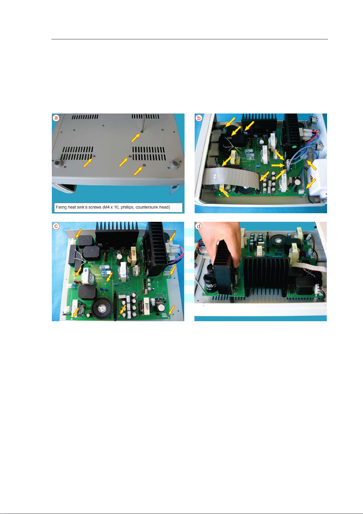
SS-501LX / SX Service Manual
Technical Information
2.8.4 - DISASSEMBLING OF THE MB BOARD
Sequence:
To disassemble front and rear panels, see items 2.8.2 and 2.8.3.
a – Remove the 04 screws that fix the heat sink of the MB board;
b – Disconnect all associated cables;
c, d – Unfasten the 08 pieces that fix the MB board.
Page 2.12

SS-501LX / SX Service Manual
Maintenance Routine
Maintenance Routine
CHAPTER 3
This section introduces information for preventive and corrective maintenance of the
equipment described in this manual and presents the associated precautions related to the
servicing of the unit.
Safety Standard:
The non-observance in the instructions contained in this manual and in the user manual of
the related unit can result in personal accidents to the surgical team and the patient.
Many of the risks relate to safety are related to the execution of maintenance and repair
procedures inappropriately.
Do not execute any maintenance service, unless you:
- have received a technical training and is qualified to work with this unit;
- read and follows the instructions contained in this manual;
- follows the safety standards of the company and the regulations of the workplace;
- have the required tools and testers, besides a properly servicing center.
Page 3.1

SS-501LX / SX Service Manual
Maintenance Routine
3.1 – PREVENTIVE MAINTENANCE
WEM recommends that qualified service personnel perform the preventive maintenance twice
a year.
____________
⇒ NOTE
Perform this inspection to assure that the equipment presents or not any irregularity. The target
here is to verify the complete functioning of the equipment.
Record the test results for future maintenance reference.
____________
REQUIRED TEST EQUIPMENT:
a – Electrosurgical analyzer, Fluke, model 454A with up to 2000Ω load or SPL
Elektronik, model HF-400;
b – PPM Test (0 to 200Ω);
c – Digital multimeter, Fluke, model 115 – True RMS Multimeter, or equivalent.
CHECKING SEQUENCE:
1 – Visually inspect the external part of the equipment:
Case: Check overall conditions (e.g. if it is not dented).
Rear panel: Check the on/off switch, the footswitch connectors, the fuse holder cover
and fuses (check it for proper values).
Front panel: Check the polycarbonate panel, display, keys and connections.
2 – Make sure that nothing unattached is inside the equipment.
3 – Turn the equipment on and check the general conditions of functioning:
Check if all indication lights and display light properly;
Check the activations of footswitches (single and double) and handswitch, functioning
tones
Check keys and fault conditions.
4 – Check inner parts:
Remove the top case;
Check the integrity of inner connections;
Check if there are residues of cleaning products in the board or in the inner part of the
equipment. If necessary, clean the board and/or the inner part of the equipment;
Check if all terminals and connectors are in good condition and with good pressure. If
necessary, replace them;
Put the top cover back.
5 – Check output powers of the equipment according to item 2.3, of this manual;
Check the linearity in 20 and 50% of the maximum rated output power, in all functions.
6 – Measure the high frequency leakage current.
7 – Check insulation between output power outlets.
8 – Check the conditions of automatic selection voltage in 110VAC and in 220VAC.
⇒
TIP: measure the voltage in pins 3 and 4 of CN1 connector (MB board).
9 – Inspect all accompanied accessories, including power cord and footswitch cables.
Page 3.2

SS-501LX / SX Service Manual
Maintenance Routine
PROBLEM
OBSERVATIONS
- attention: Stop surgery
Check all accessory connections and make sure there is no
tends to cause more stimulation than cut due to
cause neuromuscular stimulation since the procedure does not
involve sparking.
- Check if the grounding wires of power cords to all the devices
Check the integrity of grounding connection of the generator
Check if the grounding circuit of the electric installation of t he
accessory cable connections.
Interference may occur if there are sparks between metallic
Fulguration tends to cause more stimulation than cut. Lower
power levels will cause less interference.
- Check plate cable and accessory connections. Interference
may occur if there are sparks between metallic parts due to
as close as possible to the surgery site and keep the electricity
path as distant from cardiac muscles as possible.
3.2 CORRECTIVE MAINTENANCE
3.2.1 PROBLEMS THAT CAN OCCUR DURING A SURGICAL PROCEDURE
bad contact.
Neuromuscular
Stimulation
Interference in heart
monitor
Note:
- Lower power levels will cause less neuromuscular stimulation;
- Fulguration
the higher voltage levels applied. Desiccation is not expected to
are not broken;
and the monitor;
operating room is adequate;
- Check patient plate and
Interference in
pacemakers
parts due to inadequate connections;
-
inadequate connections;
- The use of bipolar instruments should be favored;
- When monopolar instruments are used, place the patient plate
Page 3.3

SS-501LX / SX Service Manual
Maintenance Routine
Error
Code
Related
Function
Power off and on the equipment without connected
system. Contact the Technical Assistance.
Power off and on the equipment without pressing the panel
Contact the authorized technical assistance.
Power off and on the equipment without pressing the panel
Contact the authorized technical assistance.
More than a
simultaneously
Power off and on the equipment without pressing any keys on
Contact the authorized technical assistance.
Power off and on the equipment without pressing the panel
Contact the authorized technical assistance.
Power off and on the equipment without pressing the panel
Contact the authorized technical assistance.
EEPROM
memory
Display values
and calibration
Defect in EEPROM memory. Contact the authorized technical
assistance.
Power off and on the equipment without connected
system. Contact the Technical Assistance.
Power off and on the equipment without pressing the
persists, contact the authorized technical assistance.
Power off and on the equipment without pressing the
technical assistance.
Power off and on the equipment without pressing the pencil
problem persists, contact the authorized technical assistance.
Power off and on the equipment without pressing the
problem persists, contact the authorized technical assistance.
3.4 SELF TEST
When the ESU is switc hed on, i t runs a se lf-test and in certain f ault situat ions, an error c ode is sho wn
on display as per the table below:
Fault
16 System Auto Test
17
18
19 - 31
20
24
Continuously
activated key
Continuously
activated key
Continuously
activated key
Continuously
activated key
Continuously
activated key
Mode
selection
Up/Down
control
panel key
activated
MEMORY
eCUT
Function &
STAND BY
Description
accessories.
If the error message remains, there is a defect in Auto Test
key (HIGH CUT, PURE, BLEND1, BLEND2, BLEND3,
FULGURATE, DESICCATE, BIPOLAR and MICRO).
If the error message remains, there is a defect in the key.
key (UP and DOWN).
If the error message remains, there is a defect in the key.
the panel).
If the error message remains, there is a defect in the keys.
key (SAVE, LOAD and REMOTE).
If the error message remains, there is a defect in the key.
key (eCUT and STAND BY).
If the error message remains, there is a defect in the key.
64 - 79
80 System Auto Test
Footswitches
simultaneously
activated
Bipolar
Footswitch
Pencils
activated
simultaneously
Monopolar 1
pencil
81
82
83
84
Continuous
activation
BIPOLAR
continuously
activated
Continuous
activation
Continuous
activation
accessories.
If the error message remains, there is a defect in Auto Test
switching levers of footswitches.
If the error message remains after releasing the footswitches,
disconnect the footswitches on back panel. If the problem
switching lever CUT in bipolar footswitch.
If the error message remains after releasing the CUT switch
on BIPOLAR footswitch, try to disconnect the footswitches on
back panel. If the problem persists, contact the authorized
switches.
If the error message remains after releasing the pencil
buttons, try to disconnect the pencils on the front panel. If the
monopolar 1 pencil switches.
If the error message remains after releasing the pencil
buttons, try to disconnect the pencils on the front panel. If the
Page 3.4

SS-501LX / SX Service Manual
Maintenance Routine
Power off and on the equipment without pressing the
problem persists, contact the authorized technical assistance.
Power off and on the equipment without pressing the CUT
assistance.
Power off and on the equipment without pressing the CUT
assistance.
Power off and on the equipment without pressing the COAG
assistance.
Power off and on the equipment without pressing the COAG
assistance.
Power off and on the equipment without pressing the
the authorized technical assis tanc e.
Power off and on the equipment without pressing the CUT
problem persists, contact the authorized technical assistance.
Power off and on the equipment without pressing the CUT
problem persists, contact the authorized technical assistance.
Power off and on the equipment without pressing the COAG
problem persists, contact the authorized technical assistance.
Power off and on the equipment without pressing the COAG
problem persists, contact the authorized technical assistance.
85
86
87
88
89
Continuous
activation
Continuously
activated
CUT
Continuously
activated
CUT
Continuously
activated
COAG
Continuously
activated
COAG
Monopolar 2
pencil
Monopolar 1
footswitch
Monopolar 2
footswitch
Monopolar 1
footswitch
Monopolar 2
footswitch
monopolar 2 pencil switches.
If the error message remains after releas ing the pe ncil
buttons try to disconnect the pencils on the front panel. If the
switching lever on monopolar 1 footswitch.
If the error message remains after releasing the CUT
footswitch, try to disconnect the footswitch on back panel. If
the problem persists, contact the authorized technical
switching lever on monopolar 2 footswitch.
If the error message remains after releasing the CUT
footswitch, try to disconnect the footswitch on back panel. If
the problem persists, contact the authorized technical
switching lever on monopolar 1 footswitch.
If the error message remains after releasing the COAG
footswitch, try to disconnect the footswitches on back panel.
If the problem persists, contact the authorized technical
switching lever on monopolar 2 footswitch.
If the error message remains after releasing the COAG
footswitch, try to disconnect the footswitches on back panel.
If the problem persists, contact the authorized technical
90
91
92
93
94
Continuously
activated
BIPOLAR
Continuously
activated
CUT
Continuously
activated
CUT
Continuously
activated
COAG
Continuously
activated
COAG
Bipolar
footswitch
Monopolar 1
pencil
Monopolar 2
pencil
Monopolar 1
Pencil
Monopolar 2
Pen
switching lever COAG on bipolar footswitch.
If the error message remains after releasing the COAG
switch on BIPOLAR footswitch, try to disconnect the
footswitches on back panel. If the problem persists, contact
button on monopolar 1 pencil.
If the error message remains after releasing the pencil CUT
button try to disconnect the pencil on the front panel. If the
button on monopolar 2 pencil.
If the error message remains after releasing the pencil CUT
button try to disconnect the pencil on the front panel. If the
button on monopolar 1 pencil.
If the error message remains after releasing the pencil COAG
button, try to disconnect the pencil on the front panel. If the
button on monopolar 2 pencil.
If the error message remains after releasing the pencil COAG
button, try to disconnect the pencil on the front panel. If the
Page 3.5

SS-501LX / SX Service Manual
Maintenance Routine
Power off and on the equipment without pressing the bipolar
assistance.
Power off and on the equipment without connected
system. Contact the Technical Assistance.
Power off and on the equipment without connected
authorized technical assistance.
Power off and on the equipment without connected
authorized technical assistance.
Power off and on the equipment without connected
assistance.
Power off and on the equipment without connected
Contact the authorized technical assistance.
Power off and on the equipment without connected
authorized technical assistance.
Power off and on the equipment without connected
fully interrupted. Contact the authorized technical assistance.
Power off and on the equipment without connected
Contact the authorized technical assistance.
Power off and on the equipment without connected
authorized technical assistance.
Power off and on the equipment without connected
assistance.
Continuously
95
128 System Auto Test
129
130
131 to
254
132
activated
BIPOLAR
Incorrect RF
power
Incorrect RF
power
Incorrect RF
power
Incorrect RF
power
Bipolar
footswitch
Fault in power
control
Fault in power
control for low
loads
Fault in power
control
Fault in open
or high load
power control
footswitch levers.
If the error message remains after releasing the BI PO LAR
footswitch, try to disconnect the footswitch on back panel. If
the problem persists, contact the authorized technical
accessories.
If the error message remains, there is a defect in Auto Test
accessories.
If the error message remains, a fault was detected in voltage
sensor circuit during the automatic power test. Contact the
accessories.
If the error message remains, a fault was detected in current
sensor circuit during the automatic power test. Contact the
accessories.
If the error message remains, multiple problems were
detected in power control. Contact the authorized technical
accessories.
If the error message remains, a fault was detected in leakage
current sensor circuit during the automatic power test.
136
144
145
160
162
Incorrect RF
power
Incorrect RF
power
Incorrect RF
power
Incorrect RF
power
Incorrect RF
power
Fault in
leakage
current control
Fault in
redundant
power control
Fault in power
control
Fault in
redundant
power control
for low loads
Fault in power
control for low
loads
accessories.
If the error message remains, a fault was detected in load
sensor circuit during the automatic power test. Contact the
accessories.
If the error message remains, the internal power supply
reached a power value above the specified va lue and was
accessories.
If the error message remains, the internal power supply
reached an overpower condit ion and was fully interrupted.
accessories.
If the error message remains, a fault was detected in shortcircuit sensor during the automatic power test. Contact the
accessories.
If the error message remains, the internal power supply for
low loads reached a power value above the specified value
and was fully interrupted. Contact the authorized technical
Page 3.6

SS-501LX / SX Service Manual
Maintenance Routine
Power off and on the equipment without connected
authorized technical assistance.
Power off and on the equipment without connected
current sensor. Contact the authorized technical assistance.
Power off and on the equipment without connected
assistance.
192
226
255
Incorrect RF
power
Incorrect RF
power
Incorrect RF
power
Fault in power
control
Fault in power
control
Power module
accessories.
If the error message remains, a fault was detected in power
compensation circuit of HI PURE mode. Contact the
accessories.
If the error message remains, a fault was detected in the
accessories.
If the error message remains, a fault was detected in CN1
and CN2 connections. Contact the authorized technical
Page 3.7

SS-501LX / SX Service Manual
Schematic Diagrams
Schematic Diagrams
CHAPTER 4
This section presents the schematic diagrams related with the maintenance of the main
failures of the equipment.
Page 4.1

SS-501LX / SX Service Manual
Schematic Diagrams
4.1 – SCHEMATIC DIAGRAMS
4.1.1 –
a) Power Supply
CPU BOARD
b) Connections CPU / MB Boards
Page 4.2

SS-501LX / SX Service Manual
Schematic Diagrams
4.1.2 – MB BOARD
a) Power Supply
b) Insulation and Output Circuit
Page 4.3

SS-501LX / SX Service Manual
Schematic Diagrams
c) Footswitch Activation Circuit
Page 4.4

SS-501LX / SX Service Manual
Calibration and Adjust
Calibration and Adjust
CHAPTER 5
This section introduces information for calibration of the electrosurgical generator, model
SS-501LX / SS-501SX, as well as the required tools for this activity.
Terminology
Calibration:
“Operation that establish, in a first stage and under specified conditions, a relation between the values and
associated uncertainty; in a second stage, uses this information to establish a relation with the aim of obtaining
a measurement result from an indication.” (VIM 2.39, 2008)
Adjust:
“Set of performed operations in a measurement system, in a way that it provides prescribed indications
correspondent to determined values of a magnitude to be measured.” (VIM 3.11, 2008)
Summarizing:
Calibration refers to the ac t of comparing the readings of a DUT with es tablished values, and the Adjust refers
to the act of preceding the maintenance service of the equipment, until it returns to read under the parameters
established by the manufacturer.
NOTE: The adjust of a system must not be confused with calibration, which is a pre requirement to the
adjust.
Safety Standard:
Do not execute any calibration servicing, unless you:
- have received a technical training and is qualified to work with this unit;
- read and follows the instructions contained in this section;
- follows the safety standards of the company and the regulations of the workplace;
- have the required tools and testers, besides a properly servicing center.
Page 5.1

SS-501LX / SX Service Manual
Calibration and Adjust
5.1 CALIBRATION AND ADJUST
____________
⇒ NOTE
Before starting the calibration, make sure that the version of the software is the s ame a s thi s
procedure. In doubt, check item 2.7 – Software version, in this service manual.
____________
REQUIRED INSTRUMENT
• Electrosurgical analizyer, Fluke model 454A with selectable load up to 2000 ohms or
SPL Elektronik, model HF-400;
• Digital multimeter, Fluke, model 115 – True RMS Multimeter, or equivalent.
• Electrosurgical unit’s accessories (patient plate, handswitch and/or handpiece controlled
by footswitch, bipolar forceps, single and/or double footswitch);
• PPM test (0 to 200Ω);
5.1.1 CHECKING OF OUTPUT POWER AND PATIENT PLATE CIRCUIT
CHECKING OF PPM / PLC CIRCUIT
____________
PPM / PLC CIRCUIT
PLC – use of the single patient plate
PPM – use of the double (split) patient plate
It’s necessary the PPM test specified above for checking and/or adjust.
____________
01. Check the PPM/PLC circuit.
OUTPUT POWER CHECKING
01. Check output power in all functions of Monopolar and Bipolar modes, in Monopolar 1,
Monopolar 2 and Bipolar outlets.
02. Check high frequency leakage current.
03. Check insulation between outlets.
Page 5.2

SS-501LX / SX Service Manual
Parts and Spares
Parts and Spares
CHAPTER 6
This section presents the main parts of the electrosurgical microprocessed generator,
model SS-501LX / SS-501SX and the spare part list suggested by WEM to have in stock
The use of non-original or non-indicated spare parts by WEM can put in risk the
accomplished quality service and the security of the equipment and the patient.
for a fast and effective maintenance.
Security Standard:
Page 6.1

SS-501LX / SX Service Manual
Parts and Spares
ITEM
DESCRIPTION
SS-501LX UP FRONT PANEL
SS-501SX UP FRONT PANEL
SS-501LX CPU BOARD REV.12 -SW F3.7
SS-501SX CPU BOARD REV.12 -SW F3.7
SS-501LX UP REAR PANEL
SS-501SX UP REAR PANEL
6.1 – PARTS AND SPARES
6.1.1 – EXPLODED VIEW
IDENTIFICATION OF THE PARTS:
01
02
03 SS-501SX MB BOARD REV.10 – ASS INSPECTED
04 SS-501SX UP CASE SET
05 SCREW 02940 PH M3 8 COUNTERSUNK HEAD
06
Page 6.2

SS-501LX / SX Service Manual
Parts and Spares
Polycarbonate panels are included.
CPU board is not included.
6.1.2 – FRONT PANEL
6.1.2.1 – SS-501LX FRONT PANEL
SS-501LX UP FRONT PANEL SS-501LX CPU BOARD REV.12 -SW F3.7
Software recorded. Flat cables included.
SS-501LX POLYCARBONATE PANEL - FRONT
Note: The terminal polycarbonate pane lis not sold individually.
Page 6.3

SS-501LX / SX Service Manual
Parts and Spares
Polycarbonate panels are included.
CPU board is not included.
6.1.2.2 – SS-501SX FRONT PANEL
SS-501SX UP FRONT PANEL SS-501LX CPU BOARD REV.12 -SW F3.7
Software recorded. Flat cables included.
SS-501SX POLYCARBONATE PANEL - FRONT
Note: The terminal polycarbonate pane lis not sold individually.
Page 6.4

SS-501LX / SX Service Manual
Parts and Spares
ITEM
DESCRIPTION
SS-501LX UP REAR PANEL
SS-501SX UP REAR PANEL
07
REAR PANEL PROTECTION UNIFIED
08
PLAIN WASHER 1/8”
09
SPRING WASHER 1/8”
10
NUT M3
6.1.3 – EXPLODED VIEW – SS-501LX / SX REAR PANEL
IDENTIFICATION OF PARTS:
01 CONNECTOR 06362 FEMALE XLR - 5 P NC5FP-1
02 CONNECTOR 02982 FEMALE XLR 4 P NC4FP-1
03 CONNECTOR 02982 FEMALE XLR 6 P NC6FP1
04
05 CONECTOR POWER DPST
06 SS-501SX INPUTAC BOARD - ASSEMBLED
Page 6.5

SS-501LX / SX Service Manual
Appendix
Appendix
This section presents complementary information to the service manual.
Page A1
 Loading...