

Page 1

MDMW LOW WATER SENSOR MODIFICATION KIT INSTALLATION
INSTRUCTIONS
NOTE: Installation of this kit must be done by qualified service personnel or the warranty
will be voided.
Tools Required!
Phillips screw driver Slot blade screw driver
3/8 inch nut driver 11/32 inch nut driver Razor
knife or x-acto knife
Parts List:
Heating element/high limit switch pan assembly Insulation cover/resistor
assembly Buzzer/bracket assembly Wire set wiring diagram
Instructions:
1. Remove base.
2. Remove insulation from control area and save.
3. Remove bottom insulation cover and discard.
4. Temporarily install insulation cover/resistor-assembly
5. Using the insulation cover as a template, cut rectangular hole in bottom
insulation.
6. Remove insulation cover and bottom insulation.
7. Using slot blade screwdriver, remove element clips from heater element pan.
EPC07/12/90S001-II45932 PN 45932 A
Page 2
MDMM Low Mater Sensor Modification Kit Installation Instructions
page 1
8. Remove heater element pan and discard.
9. Install heater element in heater element pan/high limit switch assembly.
10. Install heater element pan/high limit switch assembly.
11. Remove the two screws attaching the convenience outlet to the control panel.
12. Place buzzer/bracket assembly between convenience outlet and control panel. Reinstall.
13. Install bottom insulation and insulation cover/ resistor assembly.
14. Remove the control knob from the thermostat.
15. Remove the 2 screws attaching the thermostat to the control panel.
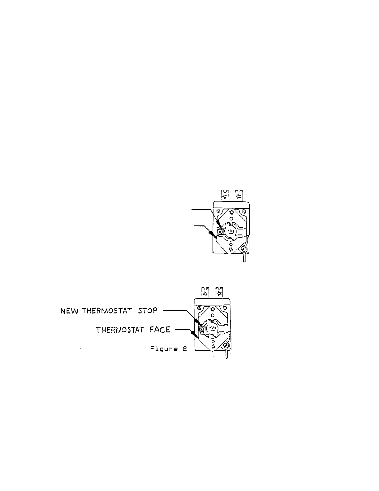
16. Lift out the thermostat and remove and discard the thermostat stop (refer to Figure 1).
THERMOSTAT STOP THERMOSTAT FACE
Figure 1
17. Install the thermostat stop supplied (refer to Figure 2).
Page 3
page 2
MDMW Low Mater Sensor Modification Kit Installation Instructions
18. Re-install thermostat in control panel and install knob.
NOTE: Steps 19 through 24, refer to attached wiring diagram.
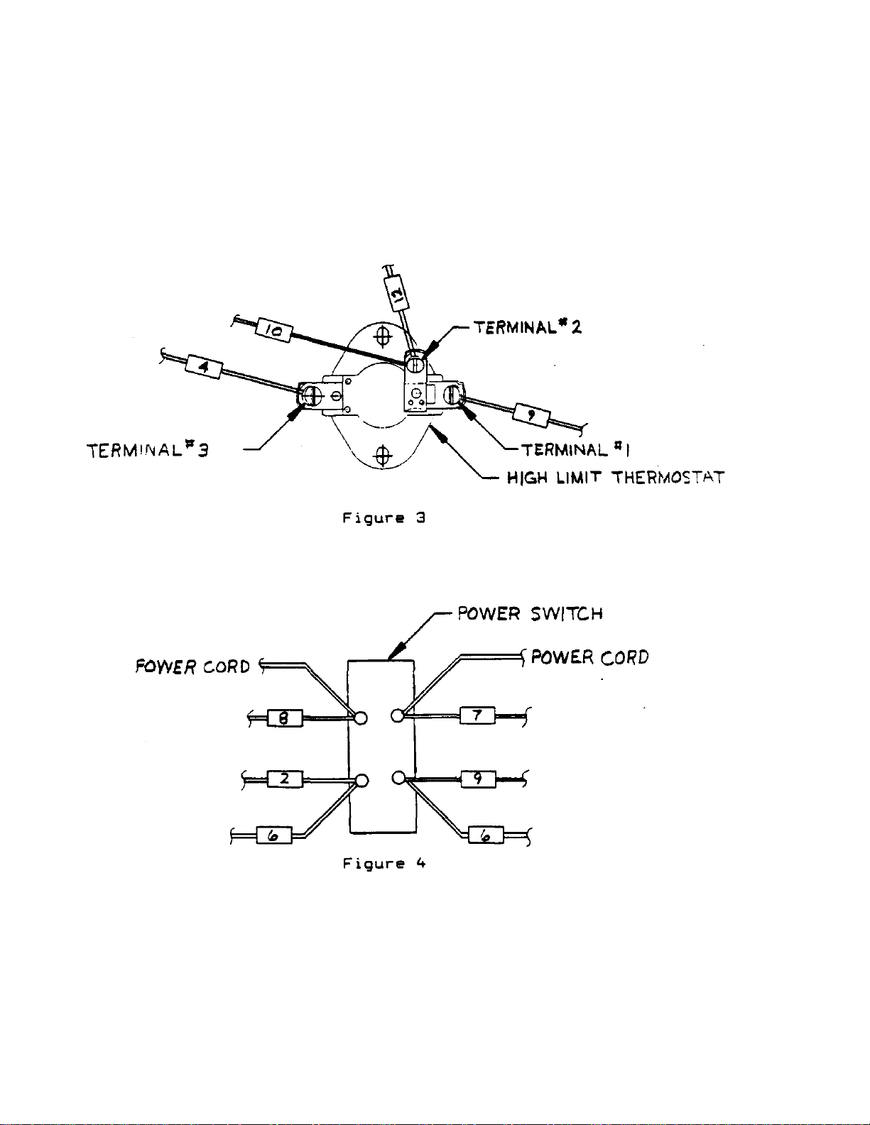
19. Remove wire #4 from on/off switch and install on high limit switch
terminal # 3 (refer to Figure 3).
20. Install wire #9 between on/off switch and high limit switch terminal # 1 (refer
to Figures 3 and 4).
Page 4

page 3
MDMW Low Mater Sensor Modification Kit Installation Instructions
21. Remove wire #6 from red power light (refer to Figure 5).
CAUTION: Be sure to remove wire that is connected to wire #2 at on/off switch,
otherwise buzzer will not operate.
22. Install wire #11 between buzzer and red power light Re-install wire #6 (refer to
Figures 5 and 6).
23. Install wire #12 between high limit thermostat terminal #2 and ballast resistor, and
wire #10 between high limit thermostat terminal #2 and buzzer (refer to Figures 3, 6
and 7).
Figure 7
Page 5

MDMW Low Water Sensor Modification Kit page 4
Installation Instructions
24. Install wire #13 between buzzer and ballast resistor (refer to Figures 6 and 7).
55. Re-install insulation around control area.
26. Re-install base.
Page 6

MDMW LOW WATER CUT OFF ADDENDUM:
Thermostat Clamp Plate)
proper air circulation.
insulation cover.
PN 46270
SH 1 OF 2
ITEM PART NO. DESCRPTION QTY. FUNCTION
20 60639 Bottom Cover Panel 1 Panel to cover electrical components at the
bottom.
21 60660
66090
22 60892 Thermostat 1 To maintain water pan temperature.
Fiberglass Insulation (Sides) (Bottom) 1 Insulation to prevent heat dissipation through
sides and bottom.
23 - Thermostat Bulb (Part of Item 22) (under
24 60598 Thermostat Clamp Plate 1 Clamps thermostat bulb to the water pan.
25 65944 Heating Element Pan and Clip Assembly 1 Clips retain heating element and element
26 60566 Heating Element 1 Heat source for marinator.
27 66107 Wiring Harness (Not shown) 1 Electrical distribution system for electrical
28 65936 Cover, Insulation 1 Panel to retain insulation.
29 60564 Feet 1 Non-skid and raises marinator off table for
30 65939 Low water thermostat 1 Turns off heating element and turns on
31 65943 Buzzer 1 Sounds alarm when water pan is dry.
32 65938 Buzzer bracket 1 Mounts Buzzer
33 65937 Ballast Resistor 1 Draws electrical current through buzzer
34 65942 Insulator 1 Insulates Ballast Resistor terminal from
1 Temperature sensing part of the thermostat
radiates heat into water pan.
components,
buzzer when water pan is dry.
contact of low water thermostat.
35 65934 Insulation 1 Insulation to prevent heat dissipation through
bottom.
HARDWARE IDENTIFICATION
ITEM PART NO. DESCRIPTION QTY.
F 55135 Screw, 1/4-20 x 3/8" (9 mm) SS Truss Head 16
K 51716 Washer. Flat #6 Monel Element 4
M 55313 Nut, Kep 10-32 4
N 50397 Clip, Heating element 5
Q 51053 Nut, Kep 8-32 3
R 61966 Bolt, 1/4 - 20 x 2 1/4 1
Page 7

Page 8

NOTE: This trouble shooting guide is in addition to trouble shooting guide in the
a. Buzzer sounds.
a. No water in water pan.
a. Add water up to the mark in water
water is added
but:
telite and no
PN 46
270 SH 2 OF 2
.
Marinator Equipment Manual.
PROBLEM PROBABLE CAUSE CORRECTIVE ACTION
pan.
b. Buzzer so unds
water is in
water pan.
c. Buzzer sounds
and will not
b. Thermostat out of calibration. b. To calibrate follow planned Maintenance Card
61.
c. Low water thermostat defective. c. Replace low water thermostat.
to pan and no heat.
d. Buzzer cycles on
and off when pan is
dry.
Buzzer does not
sound when water
pan is dry.
Power switch in ON
heat.
d. Low water thermostat cycles off after
heater element cools down.
a. Low water thermostat defective. a. Replace low water thermostat.
b. Buzzer defective. b. Replace buzzer.
c. Ballast resistor defective. c. Replace ballast resistor.
d. Water pan has just run dry. d. Normally water pan must be dry for 10-15
a. Low water thermostat defective. a. Replace low water thermostat.
d. This is normal operation. Add water up to mark
in water pan.
minutes before Buzzer will sound.
Page 9

WIRING DIAGRAM FOR MDMW-1, 2&3LWC
PLUS CONVENIENCE OUTLET
120 VOLTS. SINGLE
PHASE WITH LOW
WATER SENSOR
WATTS VOLTS NOM. AMPS
900 120 7. 5
BALLAST RESISTOR
Page 10

Wells Manufacturing Company
2 Erik Circle, P.O. Box 260
Verdi, NV 89439
(702)345-0444 May 08,1991
FAX: (702) 345-0569
SERVICE BULLETIN # 151-050891
TO: All Authorized Wells Service Centers
FROM: Allen K. Frandsen, National Service Manager
RE: Low water alarm and cut -off in Marinator Warmer.
Models covered by this bulletin: (MDMW) series McDonalds Marinators.
The Marinator Warmers manufactured for McDonalds has been upgraded to incorporate a low water
alarm and cut-off circuit. All current production units: MDMW-I, 2 and 3 now have "LWC" added to the
model identification plate.
This stands for "Low Water Cut-Off". Operation Is similar to the former models except that the unit will
shut down and sound a warning buzzer when the water has been allowed to run dry.
Attached is an addendum to the Service Manual covering the changes in the component parts, a wiring
diagram, a trouble shooting guide and a pictorial drawing.
A Retro-Fit Kit (PN:21505) is available (A copy of the instructions is attached) to modify Marinators in the field that
require the low water control circuit.
In order to successfully install the kit without difficulty, the water pan must not be warped, the thermostat
must be properly calibrated, inserts and lids must be in place. Failure to follow the instructions will result
in nuisance tripping of the alarm circuit.
AXF/dmd
Attachments: 46270 45932A
MANUFACTURERS OF QUALITY COMMERCIAL COOKING & WARMING EQUIPMENT
 Loading...