

Page 1
Printed In All Rights Reserved
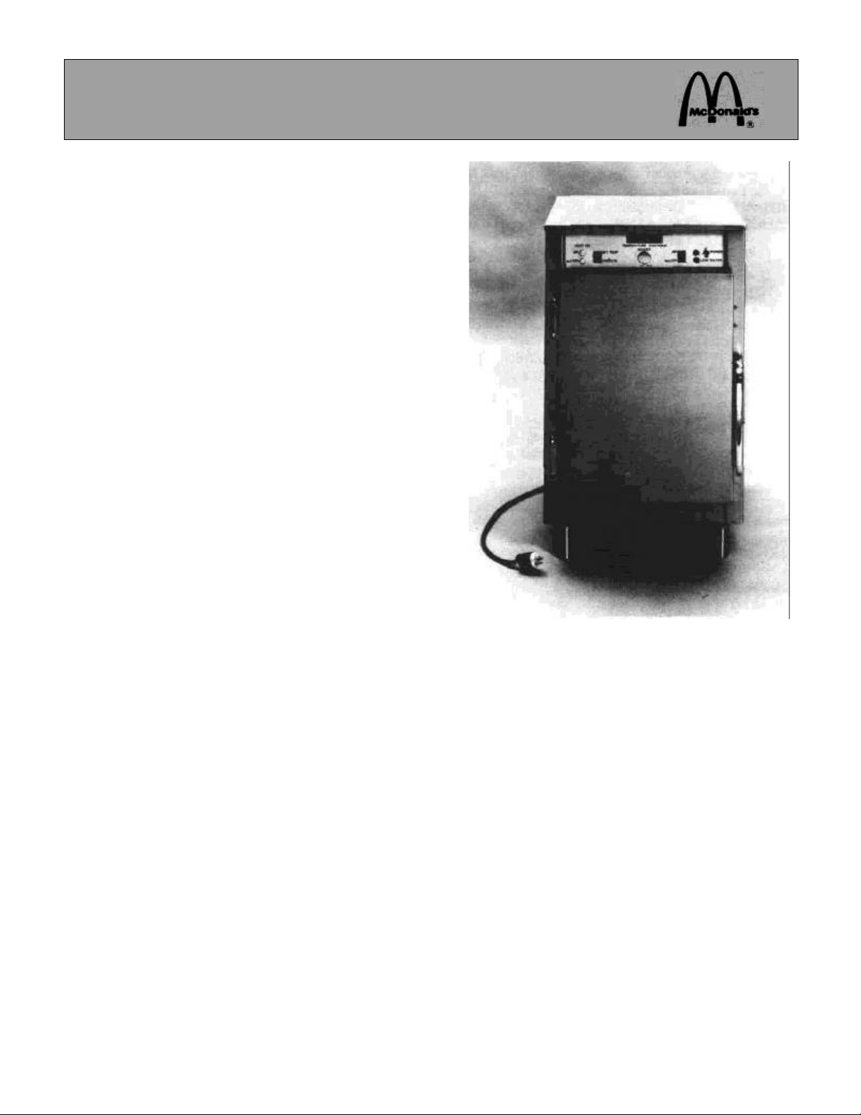
BISCUIT CABINET
WELLS MODEL MDBC-1
Place this chapter in the Cabinets Section of the Equipment
Manual.
MANUFACTURED EXCLUSIVELY FOR
McDONALD'S®
BY
WELLS MANUFACTURING 2 ERIK CIRCLE VERDI,
NEVADA 89439 PHONE: 1 (702) 345-0444 1 (800) 777-0450
TELEX: 170074
TABLE OF CONTENTS
WARRANTY................................................................................................................. Page 2
INTRODUCTION........................................................................................................... Page 2
SAFETY....................................................................................................................... Page 2
PARTS /IDENTIFICATION/PHOTO/FUNCTION ............................................................. Page 3
HARDWARE IDENTIFICATION....................................................................................Page 12
EQUIPMENT SET UP AND CLOSE PROCEDURES .....................................................Page 12
TROUBLESHOOTING .................................................................................................Page 12
ORDERING/SERVICE INFORMATION.........................................................................Page 15
NON-SCHEDULED MAINTENANCE ............................................................................Page 15
WIRING DIAGRAM......................................................................................................Page 20
WIRING PICTORIAL ....................................................................................................Page 21
This manual is for the exclusive use of licensees and employees of McDonald's Systems, Inc.
© 1985 McDonald's Corporation
Printed in September The United States of America
Page 2

WARRANTY STATEMENT
This MDBC-1 Biscuit Cabinet Manufactured by
Wells is warranted to be free from defects in
materials and workmanship for a period of one
year from the date of original installation and is for
the benefit of the original purchaser only, BUT
NOT AGAINST DAMAGE CAUSED BY ABUSE,
FAULTY INSTALLATION, INCLUDING IMPROPER ELECTRICAL CURRENT (125 VOLTS,
AC). THIS WARRANTY IS THE COMPLETE AND
ONLY WARRANTY, THERE BEING NO OTHER
WARRANTIES, EXPRESSED OR IMPLIED IN
LAW OR IN FACT, INCLUDING BUT NOT
LIMITED TO, WARRANTIES OF MERCHANTABILITY OR FITNESS FOR ANY PARTICULAR PURPOSE, AND/OR FOR DIRECT, INDIRECT, OR CONSEQUENTIAL DAMAGES IN
CONNECTION WITH WELLS PRODUCTS.
Wells' obligation under this warranty is limited to
the repair of defects or replacement without
charge by a WELLS factory authorized service
agency or one or its sub-service agencies. This
service will be provided on customer's request.
Please contact the Service Department: Wells
Manufacturing Company, P. O. Box 280, Verdi,
Nevada 89439; to arrange service or for additional
information and other details concerning the
product and/or this warranty.
INTRODUCTION
This Commercial Biscuit Cabinet Model MDBC-1
is designed to hold food at the desired serving
temperature and moistness.
SAFETY
Knowledge of proper installation, operation and
maintenance procedures is essential to ensure
safe operation of any equipment. The instructions
in this chapter are meant as guidelines; major
considerations to be kept always in mind are:
1. Always have dry hands prior to turning
power switch on or off.
2. Turn off power switch anytime cabinet is not
in use.
3. If an electric shock is felt when touching the
cabinet, disconnect immediately. Call Wells
Service Department for repair.
4. Have electrical supply outlet installed by a
licensed electrician. Make sure that equipment is properly grounded.
5. If you find that the electrical cord is frayed,
DO NOT PLUG INTO A RECEPTACLE.
If it is already plugged in, disconnect the plug after
shutting off the circuit breaker.
6. DISCONNECT POWER CORD BEFORE
ATTEMPTING ANY REPAIRS AND/OR
CLEANING THE UNIT WITH WATER.
7. Allow unit to cool before cleaning.
8. DON'T EVER SPLASH WATER WITH A
HOSE OR OTHERWISE ONTO THE UNIT.
WET ELECTRICAL COMPONENTS AND
WIRING WILL PRESENT A SHOCK
HAZARD.
9. Follow cleaning procedures described on
the Planned Maintenance System, Card
#64.
10. CAUTION: Do not operate unit until the legs
are installed. Four (4) legs are provided and
can be installed by screwing into bottom of
unit as shown on page 10.
11. For biscuit table installation: Bolt unit legs to
table using four (4) 1/4-20 UNC x 1 1/4" long
bolts and four (4) 1 1/4" O. D. flat washers.
Apply Loctite #242 to the leg bolt threads
upon installation of the unit on to the table.
2
Page 3
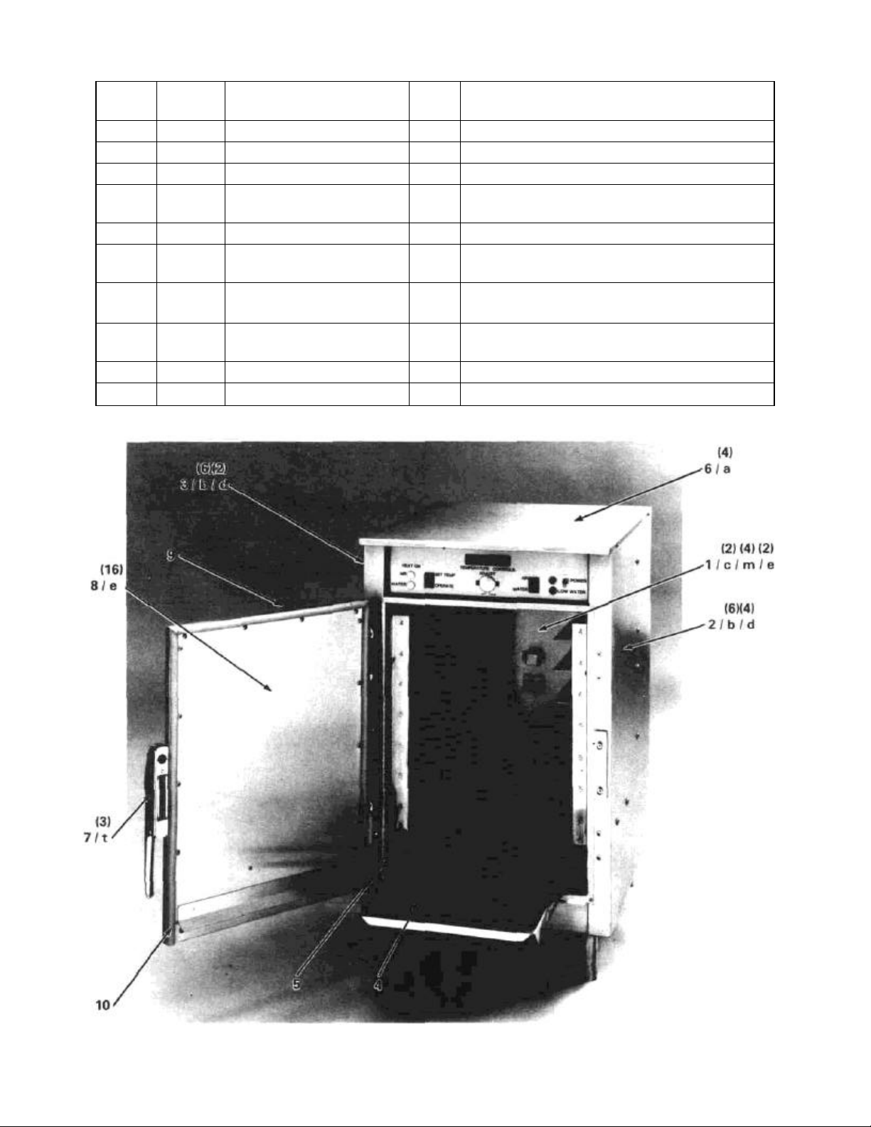
PARTS IDENTIFICATION/PHOTO/FUNCTION
ITEM PART NO. DESCRIPTION QTY. FUNCTION
1 60755 Cavity 1 Provides the Interior Surface of this Unit
2 61044 Right Side Panel 1 Outer Side of Unit
3 61043 Left Side Panel 1 Outer Side of Unit
4 60794 Crumb Shield 1 Prevents Crumbs From Falling into the water pan
5 60756 Air Heating Element 2 Heats the Air Inside of the Unit
6 60783 Cabinet Top 1 Covers and Protects Controls and Components
7 60786 Door Handle and Plate Assy 1
8 60804 Door Interior Panel 1 Secures the Door Gasket and Protects Insulation
9 60820 Door Gasket 1 Seal to Retain the Interior Environment
10 60790 Door 1 Allows Access to the Interior Cavity
Provides Access to Unit and Secures the Door when
Closed
3
Page 4
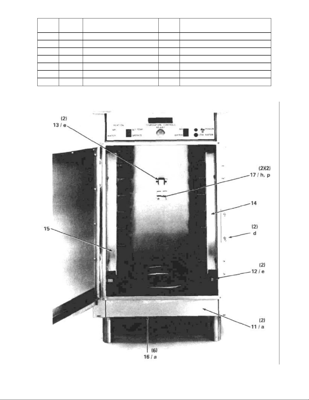
ITEM
11 60779 Front Bottom Panel 1 Protective Front Cover
12 60752 Element Clip 2 Holds Element in Place
13 60789 Thermo Bracket 1 Protective Guard for the Air Sensor
14 60760 Right Tray Rack 1 Holds Right Side of Biscuit Tray
15 60760 Left Tray Rack 1 Holds Left Side of Biscuit Tray
16 60784 Bottom Cover 1 Protective Bottom Cover
17 61105 Air Probe Bracket 1 To Hold the Biscuit Oven Probe
PART
NO.
DESCRIPTION QTY. FUNCTION
4
Page 5
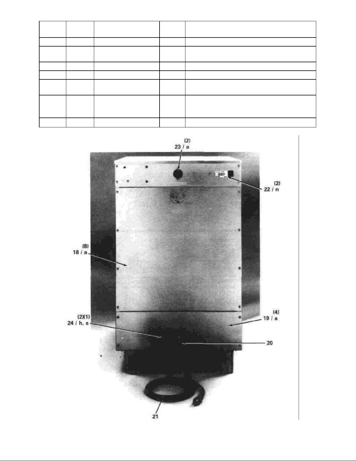
ITEM PART NO. DESCRIPTION QTY. FUNCTION
18 60771 Rear Panel 1 Protective Rear Cover
19 61735 Lower Back Panel 1
20 60589 Strain Relief 1 Attaches Cord to Unit
21 61050 Cord Set 1 Transfer Electric Power to Unit
22 60809 Specification Plate 1
23 60590 Convenience Outlet 1
24 53068 Terminal Block 1 Distribute Power to Components
Electrical Components Mounting and Protective Lower
Back Cover.
Indicates Model Number, Serial Number and Electrical
Rating of the Unit
120V, 4 Amp, 500 Watt max. Outlet for limited Usage
Device. Electrically "hot" when cabinet cord is plugged
in.
5
Page 6
ITEM PART NO. DESCRIPTION QTY. FUNCTION
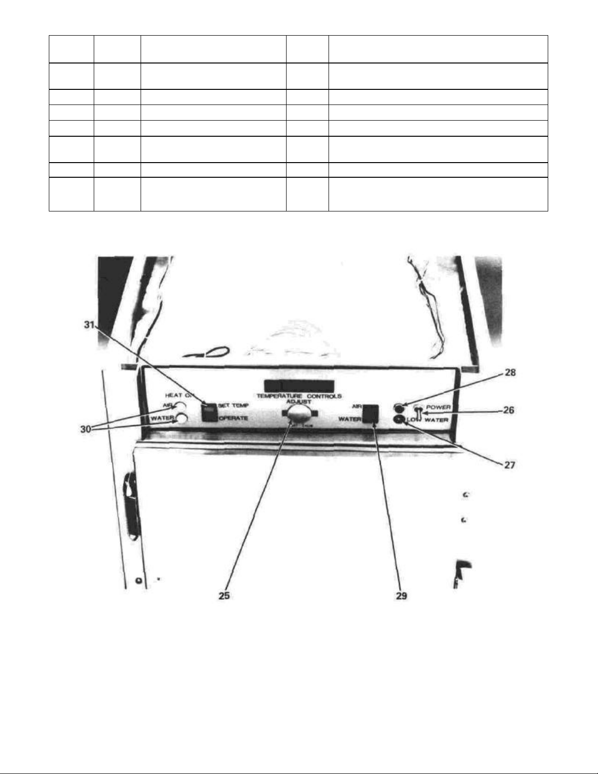
25 60830 Plug 1
26 50169 Power Switch 1 Turns Electric Power On or Off to the Unit
27 60825 Water Telite (Amber) 1 Low Water Warning Light
28 60758 Power Telite (Red) 1 When Lit, Indicates the Power is On to the Unit
29 60763 Air/Water (Rocker) Switch 1
30 60563 Thermostat Telite (White) 2 Indicates Heater is On
31 60763 Mode (Rocker) Switch 1
Provides Access to Controls for Adjusting and Setting
the Temperatures
To Select Which System the Temperature Readout
Indicates. (Air or Water)
Set Temperature Displays in a Flashing Manner, the
Temperature at Which the Control is Set to Operate:
OR Displays the Actual Temperature
6
Page 7
ITEM
PART
NO.
DESCRIPTION QTY. FUNCTION
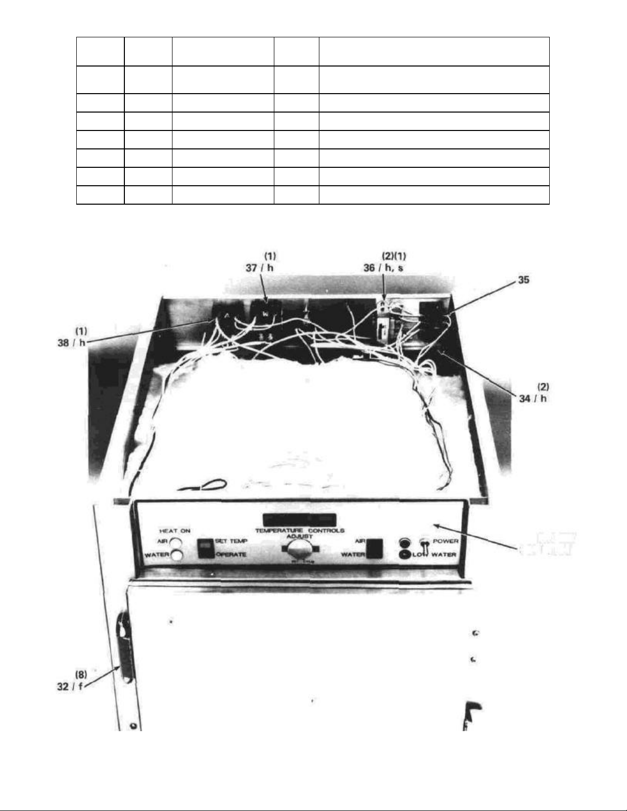
32 60787 Door Hinge 2
33 60795 Control Panel 1 Used to Mount Electrical Control Components
34 50252 Terminal Block 1 To Distribute Power to the Components
35 54005 Jumper Strap 1 The Electrical Supply Neutral Terminal
36 60818 Transformer 1 Provides Low Voltage to the Printed Circuit Board
37 60964 Water Relay 1 Turns the Water Heater On and Off
38 60870 Air Relay 1 Turns the Air Heaters On and Off
Mounts Door to Cabinet and Allows the Door to Open
and Close
(2) (2X2)
33 / h. p, j
7
Page 8
ITEM
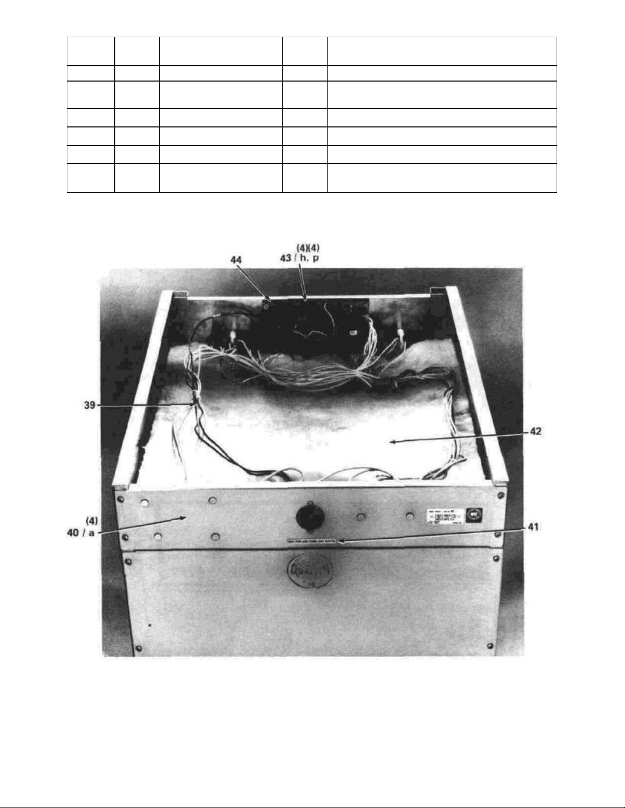
39 60863 Wire Harness 1 Permits Connection of All Electrical Parts
40 60778 Rear Top Panel 1
41 60565 Label 1 Rating Size for Convenience Outlet (500 Watts max.)
42 60824 Top Insulation 1 Insulates Controls From the Heated Cavity
43 60816 Printed Circuit Board 1 Solid State Device. Controls All Functions
PART
NO.
DESCRIPTION QTY. FUNCTION
Electrical Components Mounting and Protective Upper
Rear Cover
44 60813 Spacer 4
Provides Required Spacing for Printed Circuit Board to
the Control Panel
8
Page 9

ITEM
45 60785 Right Side Insulation 2
46 60785 Left Side Insulation 2
47 60814 Air Temperature Sensor 1 Senses the Air Temperature Inside the Unit
48 61102 Thermo Strap 1 Holds the Air Sensor Thermostat in Place
49 61183 High Limit Thermostat - Air 1
50 60782 Lower Bottom Insulation 1
51 60777 Cavity Support Bracket 2 Rear Supports of the Cavity
PART
NO.
DESCRIPTION
QTY.
Provides Thermal Seal Between Cavity and Right Side
Panel
Provides Thermal Seal Between Cavity and Left Side
Panel
Safety Device Which Prevents Excessive Cabinet
Temperature if the Relay Fails
Provides Thermal Seal Between the Water Heater and
the Bottom Cover
FUNCTION
9
Page 10

ITEM
52 60751 Upper Bottom Insulation 1 Thermal Seal Around the Water Pan
53 60764 Leg 4 Allows for Cleaning Under Cabinet
54 60810 Heater Element Retainer 1 Holds Water Heating Element in Place
55 60527 High Limit Thermostat-Water 1
56 60768 Water Heating Element 1 Heats the Water in the Pan
57 60815 Thermal/Low Water Sensor Assy. 1
58 60807 Water Pan 1 Holds Water for Humidity
PART
NO.
DESCRIPTION QTY. FUNCTION
Safety Device Which Prevents Excessive Water
Pan Temperature if the Relay Fails
Senses Temperature and Low Water in the
Water Pan
10
Page 11

ITEM
59 61056 Water Pan Gasket 1 Seals Water Pan to the Bottom of the Cavity
60 61030 Shoulder Washer 1 Water Seal and Sensor Insulator (Upper)
61 61031 Washer 1 Water Seal and Sensor Insulator (Lower)
PART
NO.
DESCRIPTION QTY. FUNCTION
SIDE VIEW (BOTTOM OF
CABINET)
CROSS SECTION A-A
11
Page 12

HARDWARE IDENTIFICATION
ITEM PART NO. DESCRIPTION QTY.
a 54910 Screw, Pan Hd. Phil. #8-32 UNC X 3/8 Lg 30
b 60670 Screw, Truss Hd. #1/4-20 UNC X 3/8 Lg 12
c 54285 Screw, Fl. Hd. Phil. #8-32 UNC X 3/8 Lg 2
d 53971 Screw, Pan Hd. Phil. #10-32 UNF X 3/8 Lg 10
e 61620 Screw, Truss Hd. Phil. SS #8-32 UNC X 1/2 Lg 22
f 60822 Screw, Fl. Hd. Phil. SS #10-32 UNF X 1/2 Lg 8
9 61048 Bolt, Hex Hd. #1/4-20 UNC X 3/4 Lg 4
h 51053 Nut, Hex #8-32 UNC 22
j 54222 Washer, Flat #10 4
k 60874 Washer, Lock Zinc Plate 5/16 2
m 61020 Washer Assembly 4
n 54284 Rivet 2
P 52242 Washer, Flat #8 15
r 61036 Nut, Hex SS 5/16-18 UNC 3
s 55736 Nut, Hex Green #8-32 UNC 2
t 60821 Screw, Fl. Hd. SS #10-32 UNF X 1 1/2 Lg 3
u 60680 Nut, Hex #10-32 UNF 2
SET UP AND CLOSE PROCEDURES Set
Up - Complete the Following:
Using a clean damp cloth, wipe out the water pan
and interior of the cabinet.
Wipe down the exterior of the cabinet.
Ensure that the power cord is plugged into the
appropriate receptacle.
Ensure that water pan has melted ice and is approximately two-thirds (2/3rds) full.
Ensure that temperature setting for both air and
water (flashing digital display) is set correctly.
Allow the unit to warm up for 45 minutes before
placing product inside.
Close - Complete the Following:
Turn the power switch to the off position.
Unplug power cord from receptacle, allow unit to
cool down..
CAUTION: Equipment and water contents are hot,
heaters will burn you! Allow the cabinet to "Cool
Down". Wait approximately 60 minutes (1 hour) with
door "Open".
Remove the crumb shield and side racks.
Sponge out the remaining water in the water heater
pan.
Replace the side racks.
Fill the water pan with ice or melted ice.
Replace the crumb shield.
TROUBLESHOOTING
In servicing equipment which has malfunctioned, it
is very important to:
1. DEFINE the problem and accurately determine
what is the malfunction.
2. Determine the BASIC CAUSE.
3. ELIMINATE the cause and repair the
malfunction (obviously, if the cause is not
properly identified and eliminated, the
malfunction may recur).
It is usually relatively easy to define the malfunction, but sometimes very difficult to spot the cause.
If the problem remains after following the suggestions listed, contact Wells Manufacturing
Company at (702) 345-0444.
12
Page 13

TROUBLESHOOTING GUIDE
PROBLEM PROBABLE CAUSE CORRECTIVE ACTION
Unit Fails to Operate (No Telite
Indications)
Power Off. Turn power "ON".
Faulty power switch. Replace power switch. (See page 15).
No power to unit. Check circuit breaker, check voltage supply to unit.
Air temperature set too high. Adjust air temperature setting (See PMS Card #64.) Holding Temperature too High
Food too Dry
Above Set Temperature and
the Telite Does Signal Power
to the Heaters
Actual operating temperature
higher than set temperature.
Air temperature set too low. Adjust air temperature setting (See PMS Card #64.) Holding Temperature too Low
Actual operating temperature
lower than set temperature.
Air temperature set too high. Adjust air temperature setting. (See PMS Card #64.)
Door gasket leak. Adjust door. (See Page 18.)
Water temperature too low. Adjust water temperature setting. (See PMS Card #64.)
Low water level.
Air temperature set too low. Adjust air temperature setting. (See PMS Card #64.) Food too Moist
Water temperature set too high. Adjust water temperature setting. (See PMS Card #64.)
Thermostat out of calibration. Recalibrate the unit. (See PMS Card #64.) Air or Water Temperature is
Defective printed circuit board or
defective relay.
Recalibrate the unit. (See PMS Card #64.)
Recalibrate the unit. (See PMS Card #64.)
1. Check low water indicator, should be on and sounding.
2. Refill with water.
Consult Wells Authorized Service Agency for repair.
Below Set Temperature and
the Telite Does Not Signal
Power to the Heaters
Below the Set Temperature
and the Telite is Constantly On
-
Thermostat out of calibration. Recalibrate the unit. (See PMS Card #64.) Air or Water Temperature is
Defective printed circuit board or
defective relay.
Defective heating element. Replace element. (See page 17 for Water or Air). Air or Water Temperature is
High limit thermostat-water,
defective (For water only).
Consult Wells Authorized Service Agency for repair.
Replace high limit thermostat-water (See page 19).
13
Page 14

PROBLEM PROBABLE CAUSE CORRECTIVE ACTION
Low Water Indicator On, But
the Water Tray is Full
Display Not Lit
Short circuit between
thermal/low water sensor assy.
and water pan.
Defective printed circuit board. Replace printed circuit board. (See page 16).
Soft or distilled water being
used.
Cavity temperature too high. Check calibration after unit cools and display is lit. Power On (Red) Telite Lit;
High limit thermostat-Air
defective.
PROCEDURE TO ATTACH OVEN PROBE TO
CABINET
1. Hold Biscuit Oven Probe with Sloped Angle
Toward Cavity Rear and with the Alligator Clip at
the Bottom on the Right Side.
2. Move the Biscuit Oven Probe Up Above the Air
Probe Bracket (Item 17) and Move it Back Near
the Rear Wall of the Cavity (Item 1).
3. Move the Biscuit Oven Probe Down on to the Air
Probe Bracket (Item 17) so that the Narrow Section of the Tapered Angle (Cobra Neck) of the
Biscuit Oven Probe fits into the Slot in the Air
Probe Bracket (Item 17).
4. Push the Biscuit Oven Probe Down on to the Air
Probe Bracket (Item 17) Until it Stops.
Replace shoulder washer (Item 60) and washer (Item 61)
(See page 18) (Procedure to replace the thermal/low water
sensor assy.)
Use a pinch of salt in the water pan.
Replace defective high limit thermostat-Air (See page 17).
14
Page 15

PARTS ORDERING/SERVICE INFORMATION
If service parts or technical information is required,
please contact the Factory Service Department. To
help speed up your inquiry the following information
is required:
1. Model Number: MDBC-1
2. Serial Number:
(Fill in for your records.)
3. Voltage: 125V. A. C.
4. Item Part Number:.
5. Quantity Required:
6. Nature of Service problem and symptoms.
7. Any other information that may be helpful in
solving your service problem.
NON-SCHEDULED MAINTENANCE
Under normal conditions, with proper use and
cleaning, very little non-scheduled maintenance will
be required for this unit. However, this section
provides procedures for checking and replacement
of the various parts used within the cabinet in the
event that it becomes necessary. Before
replacement of any parts, refer to the
Troubleshooting Section for assistance in determining the cause of any malfunction to insure that
maintenance is required.
WARNING: The procedures contained in this
section involve accessing bare electrical terminals
and exposes one to voltages capable of producing
fatal shock.
NOTE: Loctite #242 should be applied to all
threaded hardware parts before reassembly (except
electrical wire connection terminals).
Procedure To Replace A Telite (Red or
White)
Tools: #2. Phillips Head Screwdriver, Needle Nose
Pliers
Parts: Telite (Item 30) White or (Item 28) Red
1. Unplug the power cord.
2. Remove the top from the cabinet.
3. Pull the wires with spade terminals off the telite.
4. Squeeze the two (2) ears on the plastic body of
the telite and push the telite out to the front.
5. Follow the reverse procedure to install a new
telite.
Procedure To Replace The Power Switch
Tools: Phillips Head Screwdriver, Pliers,
5/16 Slotted Head Screwdriver
Parts: Power Switch (Item 26)
1. Unplug the power cord.
2. Remove the top from the cabinet.
3. Unscrew the nut over the switch located on the
outside of the control panel.
4. Pull the switch out from the inside.
5. Unscrew the wire. terminals and remove.
6. Reverse procedure to install new switch.
NOTE: Ensure that ON-OFF plate or marking is in
place on the control panel and around the switch
bushing.
15
Procedure To Replace The Convenience Outlet
Tools: #2 Phillips Head Screwdriver, 5/16
Slotted Head Screwdriver
Parts: Convenience Outlet (Item 23)
1. Unplug the power cord.
2. Remove the top from the cabinet.
3. Unscrew two (2) screws holding the convenience outlet on the rear panel.
4. Pull the convenience outlet out.
5. Unscrew the wire terminals on the outlet and
remove wires.
Page 16

6. Follow reverse procedure to install new convenience outlet.
Procedure To Replace The Printed Circuit Board
Tools: 3/16 Slotted Head Screwdriver, #2 Phillips
Head Screwdriver, 11/32 Nutdriver or Open
End Wrench
Parts: Printed Circuit Board (Item 43)
1. Unplug the power cord.
2. Remove the top from cabinet.
3. Remove the wires from spade terminals by
pulling the connectors with needle nose pliers.
Step 3
1. Unplug the power cord.
2. Remove the top from the cabinet.
3. Remove the wire connectors by pulling them
from the pin connectors on the printed circuit
board.
4. Remove the air and water temperature probe
wires by loosening the screws on the
temperature probe terminal block.
5. Remove the four (4) mounting nuts located in
the corners of printed circuit board. Remove the
board from the mounting studs.
6. Follow the reverse procedure and the wiring
diagram to install a new printed circuit board.
4. Push the rocker switch through the control
panel by depressing the securing clips on the
back side of the switch body.
5. Follow the reverse procedure and the wiring
diagram to install a new rocker switch.
Procedure To Replace An Air or Water Relay
Tools: 11/32 Nutdriver, or Open End Wrench, #2
Phillips Head Screwdriver
Parts: Air Relay (Item 38) or Water Relay (Item 37)
1. Unplug the power cord.
2. Remove the top from cabinet.
3. Remove the spade terminals from the relay by
pulling the terminals off with the needle nose
pliers.
4. Remove the 11/32 nut from the mounting stud.
NOTE: The new printed circuit board will require
calibration (See PMS Card #64).
Procedure To Replace Rocker Switches
Tools: Needle Nose Pliers, #2 Phillips Head
Screwdriver
Parts: Rocker Switch (Item 29 or 31)
5. Remove the relay from its location on the mounting
stud.
6. Follow the reverse procedure and the wiring
diagram to install the replacement relay.
16
Page 17

Procedure To Replace The Water Heating
Element
Tools: Phillips Head Screwdriver, 11/32 and 5/16
Nutdrivers
Parts: Water Heating Element (Item 56)
1. Unplug the power cord.
2. Remove the bottom cover from cabinet.
3. Remove three (3) 11 /32 nuts from element retaining plate.
4. Remove three (3) 5/16 nuts from the wire terminals and remove the wires from the element.
5. Remove the element from the bottom of the
water pan.
6. Slide the element out towards the front of the
unit.
7. Follow the reverse procedure to install a new
element.
Procedure To Replace High Limit
Thermostat-Air
Tools: #8 Nutdriver, #6 Nutdriver Parts: High Limit
Thermostat-Air (Part Item 49)
1. Unplug the power cord.
2. Remove the rear panel of the cabinet.
3. Disconnect the two wires from the High Limit
thermostat-air.
4. Remove the two (2) hex nuts and washers from
the strap that holds the High Limit thermostatair in place.
5. Remove the Thermo Strap from the High Limit
thermostat-air and remove the High Limit
6. Follow the reverse procedure and the wiring
diagram to install new water heating element.
Procedure To Replace Air Heating Element
Tools: #2 Phillips Head Screwdriver, 5/16 Flat
Head Screwdriver
Parts: Air Heating Element (Item 5)
1. Unplug the power cdrd.
2. Remove biscuit pans and rack assemblies from
interior of cabinet.
3. Remove rear panel from cabinet.
4. Remove the wire terminals from the element
using the 5/16 flat head screwdriver.
5. Remove the element clip from the interior of the
cabinet using the #2 phillips head screwdriver.
thermostat-air.
6. Follow the reverse procedure to install a new
High Limit thermostat-air.
17
Page 18

Procedure To Replace The Air Temperature
Sensor
Procedure To Replace The Thermal/Low Water
Sensor Assy.
Tools: #2 Phillips Head Screwdriver, 3/16 Flat
Head Screwdriver, 112 Wrench (2 Required)
Parts: Air Temperature Sensor (Item 47)
1. Unplug the power cord.
2. Remove the top and rear of cabinet.
3. Disconnect thermocouple leads from the
printed circuit board.
4. Remove the thermoguard from the interior of
cabinet.
5. Hold the air temperature sensor on the inside
of the cabinet with a 5/16 wrench and
remove the nut on the rear of the air
temperature sensor with a 5/16 wrench.
6. Pull the air temperature sensor and the thermocouple wire through to the interior of
cabinet and remove.
7. Follow the reverse procedure to install the
replacement air temperature sensor.
Tools: #2 Phillips Head Screwdriver, 3/16 Flat
Head Screwdriver, 1 /2 Wrench (2 Required)
Parts: Thermo/Low Water Sensor Assy.
(Item 57)
1. Unplug the power cord.
2. Remove the top, rear, and bottom from the
cabinet.
3. Disconnect thermocouple leads from the
printed circuit board.
4. Hold the thermo/low water sensor assy. on the
inside of the water pan with a 5/16 wrench
and remove the nut on the rear of the
thermo/low water sensor assy. with another
5/16 wrench.
5. Pull the thermo/low water sensor assy. and
the thermocouple wire through to the interior
of cabinet and remove.
Procedure To Reverse or Adjust The Door
Assembly
Tools: #2 Phillips Head Screwdriver, 5/16 Flat
Head Screwdriver
Parts: None
1. Unplug the power cord.
2. Pry the decorative covers off the hinge
assembly with the 5/16 Flat Head Screwdriver.
Page 19

3. Remove the four (4) Phillips head screws which
attach the two (2) hinges to the cabinet (Leave
the hinges attached to the door).
4. Remove the handle and striker plate from the
door and cabinet respectively.
5. Remove the inner door panel and gasket from
the door.
6. Remove all six (6) Phillips screws from the front
of the cabinet.
7. Install the door with its hinges to the opposite
side of the cabinet.
8. Re-install the inner door panel and the gasket to
the door. (Note: The deflector should always be
at the bottom of the door).
9. Mount the handle and the striker plate to the
opposite side of the door and cabinet.
CAUTION: When mounting the handle, do not re-use
the three (3) screws "t", (P/N 60821). Discard the
previously used three (3) screws and use the new
screws supplied with the unit.
10. Adjust the handle and hinges to provide an air
tight seal along the door gasket.
11. Re-install the decorative hinge covers.
12. Re-install the six (6) Phillips head screws to fill
the un-used holes in the cabinet.
Procedure To Replace The High Limit
Thermostat (Water)
Tools: #8 Nutdriver, 5/16 Flat Head Screwdriver, #2.
Phillips Head Screwdriver
Parts: High Limit Thermostat-Water (Item 55)
1. Unplug the power cord.
2. Remove the bottom cover from the cabinet.
3. Remove the bottom outside insulation.
4. Remove the wire from the High Limit ThermostatWater using the 5/16 Flat Head Screwdriver.
5. Remove the #6 nut and washer using a #8
Nutdriver and remove the High Limit ThermostatWater.
6. Follow the reverse procedure to install a new
High Limit Thermostat-Water.
Page 20

Page 21

Page 22

MDBC-1 PASTA CONVERSION INSTRUCTIONS
P/N 46537
NOTE: If the power switch has an "Aux" position, omit Steps 2-7
1. Disconnect power supply cord (plug) from power receptacle, remove
top cover by removing the 4 screws that secure the top to the cabinet and lift off top
cover.
2. Remove original On/Off toggle type double pole power switch from
the control panel. Remove all the wires from the 4 push-on terminals.
3. Insert the new 4 pole power switch through the 15/32" hole in the control panel where
the original power switch was removed. Place the "Aux/Std" trim plate over the
threaded shaft, thread the mounting nut on the shaft and tighten the nut.
4. Reconnect original cabinet wiring per the new wiring diagram (supplied with kit).
Install new wire leads 69 through 72 supplied in the kit to the new power switch per
the new wiring diagram.
NOTE: wire 70 has an insulated terminal on one end. Install this terminal at the
power switch.
5. When wires 13 and 22 are connected to the new power switch, be sure to install the
piggy-back terminal so that the terminal is placed close to the insulated terminal of
wire 70 towards the center of the switch so that the terminals do not contact or press
on the side of the pilot light next to the switch. Install wires 11 and 12 to the
piggy-back terminals on jumpers 74 and 73. Connect the switch.
NOTE: Make sure all push-on terminals are tight. If you can remove any of these terminals by
pulling on the wires, they are not tight enough and you will have to pre-load the female
terminal (with the connector unplugged) by lightly squeezing the rolled edges of the connector
terminal with long nose pliers to ensure a tight connection between the male and female
terminals.
6. Remove jumper wire 23 that connects terminal 4 of the water relay to terminal 4 of the
air relay. Discard wire 23.
7. Connect the 4 in-line splice connectors supplied with the kit to the other end of wires
69, 70, 71, 72 and one end of wire 73. Connect the other end of wire 73 to pin 4 of
the water relay.
22
EPCOS/13/91@002-CI46937
Page 23

MDBC-1 Pasta Conversion Instructions
8. NOTE: Applies to cabinets with "AUK" power switch position only.
Remove wire 73 from the power switch and install 1 in-line splice connector
supplied with the kit to wire 73.
PRINTED CIRCUIT BOARD REMOVAL AND REPLACEMENT WITH AUXILIARY OPERATION PRINTED CIRCUIT
BOARD
NOTE: Spacers between the rear of the printed circuit board and the front control panel must
be reused when installing the new auxiliary operation printed circuit board.
9. Remove the original temperature control printed circuit board
P/N 60816 (or 63305) from the front control panel by removing the 6 wires (4, 24,
27, 28, 29 and 39) from the mounting studs. Be sure the spacers listed in the
warning above are left in place on the studs.
NOTE: On printed circuit board P/N 63305, remove the red, violet, black and orange
wires from the in-line splices.
10. Remove the thermocouple leads from the 4 pin terminal block on the upper left of the
printed circuit board.
11. Remove the air and water relay control wires (20 and 21) from the controller board
pins marked air and water.
12. Remove the orange 8 pin terminal block from the right side of the printed circuit board
by inserting a small flat blade screwdriver under the terminal block and lifting it
straight up and off the pins on the boards. (It is not necessary to remove the wires
from the terminal block to remove the block from the board.)
NOTE: There are 2 anti-static single color band resistors attached to the 4 screw terminals
on the terminal block on the left side of the printed circuit board. These 2 resistors MUST
be removed from the new controller board and reinstalled on the old controller board to
protect it from static damage during shipment.
13. Install the new printed circuit board P/N 66521 on the front control panel, reconnect wires
4, 18, 19, 20, 21, 22 and 23 to the proper push-on terminals on the board, reconnect the
thermocouple leads removed in Step 9 above, make sure the red leads are on top and the
yellow lead are on the bottom (see wiring diagram for wiring connections). Reinstall the
orange terminal block removed in Step 11 above.
23
Page 24

MDBC-l Pasta Conversion Instructions
14. Connect the orange wire from the printed circuit board to the new
wire 69, the black wire to the new wire 73, the red wire to the new wire 71, the violet
wire to the new wire 72.
NOTE: Make sure all push-on terminals are tight. If you can remove any of
these terminals by pulling on the wires, they are not tight enough and you will have to pre-load
the female terminal (with the connector unplugged) by
lightly squeezing the rolled edges of the connector terminal with long nose pliers to ensure a
tight connection between the male and female terminals.
15. Inspect general layout of components altered during this conversion
for lead dress and mounting to avoid shorting of components or wiring.
16. Fill the water pan, connect the power cord plug to the proper 120VAC supply. Place the
"Operate/Set" rocker switch to the "Set" position. Place the "Air/water" rocker switch in
the "Air" position. Turn the new "Power Switch" to the "Aux" position.
17. The digital display will be flashing, with a small flat blade
screwdriver, adjust the "Air -Set" potentiometer on the REAR of the controller printed
circuit board (adjust only the one on the small auxiliary printed circuit board attached to
the rear of the controller printed circuit board) to show a flashing 165°F (74°C).
NOTE: If the display shows a "C" in the upper window just to the right of the temperature
display, the small toggle switch located in the upper left of the printed circuit board is
switched to the Celsius position.
18. Place the "Air/Water" rocker switch in the "water" position.
19. The digital display will be flashing, with a small flat blade
screwdriver, adjust the "water Set" potentiometer on the REAR of the controller printed
circuit board (adjust only the one on the small auxiliary printed circuit board attached to
the rear of the controller printed circuit board) to show a flashing 165°F (74°C) reading.
20. Place the new wiring diagram inside the unit on top of the insulation below the top cover.
Replace the top cover on the unit, install the 4 screws removed in Step 1.
21. Set the new power switch to the "Std" position. Pry off the snap-in cover plate on the
front control panel, when looking into the hole where the snap-in cover was just removed,
you will see the adjustment potentiometers for setting the air and water temperatures for
standard operation. The upper left potentiometer is the "Air" set. Set it for l45°F
(63°C). The display will be flashing.
24
Page 25

MDBC-l Pasta Conversion Instructions
22. Position the "Air/Mater" rocker switch to the "Mater" position.
The display will be flashing. Adjust the lower left potentiometer to give a flashing 135°F
<57°C) reading. (The 2 potentiometers on the right are for calibrating the air and water.
(See Card No. 64 to adjust.)
This completes the "Pasta" conversion of the unit. A calibration check is now required! Use the
Standard Maintenance Card No. 64 published for this unit to perform the normal calibration of the
air and water sensors.
WARNING: The water pan must have water in it for calibration.
NOTE: Instruct store management personnel on the operation of the unit in the "Aux" operation
mode. Be sure to advise them that a IS minute period of stabilization of the temperature inside
is required before changing products after changing from "Aux/Std" modes. Also advise them of
the location of the auxiliary temperature "Set" potentiometer and that the adjustment cannot be
accessed through the front control panel. This adjustment can only be accessed from inside the
component area with the top removed.
25
 Loading...