

Page 1
WELLS BLOOMFIELD, LLC
10 Sunnen Dr., St. Louis, MO 63143
telephone: 314-678-6314
fax: 314-781-2714
www.wellsbloomfield.com
OPERATIONS MANUAL
FROST TOPS
416
DROP-IN
SLIM LINE
MODELS
Includes
INSTALLATION,
Model FT-3SL
USE & CARE,
SERVICE AND
WIRING DIAGRAMS
IMPORTANT: DO NOT DISCARD THIS MANUAL
This manual is considered to be part of the appliance and is to be given to the OWNER or
MANAGER of the restaurant, or to the person responsible for TRAINING OPERATORS of
this appliance. Additional manuals are available from your WELLS DEALER.
THIS MANUAL MUST BE READ AND UNDERSTOOD BY ALL PERSONS USING OR
INSTALLING THIS APPLIANCE. Contact your WELLS DEALER if you have any
questions concerning installation, operation or maintenance of this equipment.
FT-2SL
FT-3SL
FT-4SL
P/N 2M-Z16059 M418 120611
Page 2

LIMITED WARRANTY STATEMENT
Unless otherwise specified, all commercial cooking
equipment manufactured by WELLS BLOOMFIELD, LLC is
warranted against defects in materials and workmanship for
a period of one year from the date of original installation or
18 months from the date of shipment from our factory,
whichever comes first, and is for the benefit of the original
purchaser only.
THIS WARRANTY IS THE COMPLETE AND ONLY
WARRANTY, EXPRESSED OR IMPLIED IN LAW OR IN
FACT, INCLUDING BUT NOT LIMITED TO, WARRANTIES
OF MERCHANTABILITY OR FITNESS FOR ANY
PARTICULAR PURPOSE, AND/OR FOR DIRECT,
INDIRECT OR CONSEQUENTIAL DAMAGES IN
CONNECTION WITH WELLS BLOOMFIELD PRODUCTS.
This warranty is void if it is determined that, upon inspection
by an authorized service agency, the equipment has been
modified, misused, misapplied, improperly installed, or
damaged in transit or by fire, flood or act of God. It also
does not apply if the serial nameplate has been removed, or
if service is performed by unauthorized personnel. The
prices charged by Wells Bloomfield for its products are
based upon the limitations in this warranty. Seller’s
obligation under this warranty is limited to the repair of
defects without charge by a Wells Bloomfield factory
authorized service agency or one of its sub-service
agencies. This service will be provided on customer’s
premises for non-portable models. Portable models (a
device with a cord and plug) must be taken or shipped to
the closest authorized service agency, transportation
charges prepaid, for service. In addition to restrictions
contained in this warranty, specific limitations are shown in
the Service Policy and Procedure Guide. Wells Bloomfield
authorized service agencies are located in principal cities.
This warranty is valid in the United States and Canada and
void elsewhere. Please consult your classified telephone
directory, your foodservice equipment dealer or contact:
10 Sunnen Dr., St. Louis MO 63143 USA
phone (314) 678-6314 or fax (314) 781-2714
for information and other details concerning warranty.
Wells Bloomfield, LLC
SERVICE POLICY AND PROCEDURE GUIDE and ADDITIONAL WARRANTY EXCLUSIONS
1. Resetting of safety thermostats, circuit breakers, over
load protectors, and/or fuse replacements are not
covered by this warranty unless warranted conditions
are the cause.
2. All problems due to operation at voltages or phase
other than specified on equipment nameplates are
not covered by this warranty.
Conversion to correct voltage and/or phase must be
the customer’s responsibility.
3. All problems due to electrical connections not made
in accordance with electrical code requirements
and wiring diagrams supplied with the equipment are
not covered by this warranty.
4. Replacement of items subject to normal wear, to
include such items as knobs, light bulbs; and, normal
maintenance functions including adjustments of
thermostats, adjustment of micro switches and
replacement of fuses and indicating lights are not
covered by warranty.
5. Damage to electrical cords and/or plug due to exposure
to excessive heat are not covered by this warranty.
6. Full use, care, and maintenance instructions supplied
with each machine. Noted maintenance and
preventative maintenance items, such as servicing and
cleaning schedules, are customer responsibility. Those
miscellaneous adjustments noted are customer
responsibility. Proper attention to preventative
maintenance and scheduled maintenance procedures
will prolong the life of the appliance.
7. Travel mileage is limited to sixty (60) miles from an
Authorized Service Agency or one of its sub-service
agencies.
8. All labor shall be performed during regular working
hours. Overtime premium will be charged to the buyer.
9. All genuine Wells replacement parts are warranted for
ninety (90) days from date of purchase on nonwarranty equipment. This parts warranty is limited only
to replacement of the defective part(s). Any use of
non-genuine Wells parts completely voids any
warranty.
10. Installation, labor, and job check-outs are not
considered warranty and are thus not covered by this
warranty.
11. Charges incurred by delays, waiting time or operating
restrictions that hinder the service technician’s ability to
perform service are not covered by warranty. This
includes institutional and correctional facilities.
M416 p/n 2M-Z16059 Owner’s Manual Drop-In Slim Line Frost Tops
SHIPPING DAMAGE CLAIM PROCEDURE
NOTE: For your protection, please note that equipment in
this shipment was carefully inspected and packaged by
skilled personnel before leaving the factory. Upon
acceptance of this shipment, the transportation company
assumes full responsibility for its safe delivery.
IF SHIPMENT ARRIVES DAMAGED:
1. VISIBLE LOSS OR DAMAGE: Be certain that any
visible loss or damage is noted on the freight bill or
express receipt, and that the note of loss or damage is
signed by the delivery person.
2. FILE CLAIM FOR DAMAGE IMMEDIATELY:
Regardless of the extent of the damage.
3. CONCEALED LOSS OR DAMAGE: if damage is
unnoticed until the merchandise is unpacked, notify the
transportation company or carrier immediately, and file
“CONCEALED DAMAGE” claim with them. This
should be done within fifteen (15) days from the date
the delivery was made to you. Be sure to retain the
container for inspection.
Wells Bloomfield cannot assume liability for damage or loss
incurred in transit. We will, however, at your request, supply
you with the necessary documents to support your claim.
xi
Page 3
1
TABLE OF CONTENTS
WARRANTY xi
INTRODUCTION AND SPECIFICATIONS 1
FEATURES & OPERATING CONTROLS 2
PRECAUTIONS & GENERAL INFORMATION 3
AGENCY LISTING INFORMATION 4
INSTALLATION 5, 6, 7
OPERATION 8
CLEANING INSTRUCTIONS 9
MAINTENANCE INSTRUCTIONS 10, 11, 12
TROUBLESHOOTING 13
WIRING AND REFRIGERATION DIAGRAMS 14
SERVICE PARTS LIST 15
ACCESSORY PARTS & SERVICE 16
INTRODUCTION
Thank you for purchasing this Wells Bloomfield appliance.
Proper installation, professional operation and consistent maintenance of this appliance will ensure that
it gives you the very best performance and a long, economical service life.
This manual contains the information needed to properly install this appliance and to use and care for it
in a manner which will ensure its optimum performance.
MODEL HP
FT-2SL 1/4 4.9 8 11 24 R-134a 28 oz. 440 162 NEMA 5-15P
FT-3SL 1/3 5.6 11 15 29 R-404a 24 oz. 440 162 NEMA 5-15P
FT-4SL 1/2 6.4 14 18 44 R-404a 34 oz. 500 174 NEMA 5-15P
XXXX P/N XXXXX Owmer’s Manual Drop-In Slim Line Frost Tops
ELECTRICAL & REFRIGERATION SPECIFICATIONS
AMPS 120VAC 1ø REFRIGERANT
TOTAL MCA MFS LRA TYPE AMT. HIGH LOW
1
PRESSURE
(psig)
POWER
SUPPLY
CORD
Page 4
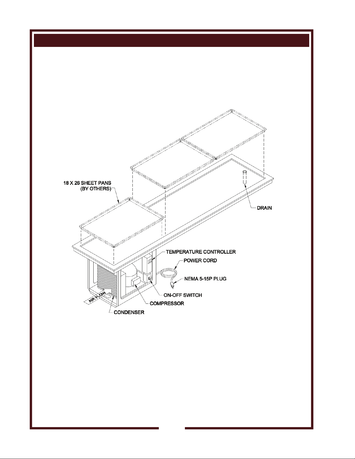
FEATURES & OPERATING CONTROLS
NOTE:
This is a general arrangement drawing only. Actual component positions may vary between units.
2
XXXX P/N XXXXX Owner’s Manual Drop-In Slim Line Frost Tops
Page 5
PRECAUTIONS AND GENERAL INFORMATION
This appliance is intended for use in commercial establishments
only, and is intended
for human consumption. No other use is
by the manufacturer or its agents.
Operators of this appliance must be familiar with the appliance use,
limitations and associated restrictions. Operating instructions must be
read and understood by all persons using or installing this appliance.
Food must be placed in appropriate inserts or sheet pans. Never place
any food directly onto the top.
Cleanliness of this appliance is essential to good sanitation. Read and
follow all included cleaning instructions and schedules to ensure the
safety of the food product.
Disconnect this appliance from electrical power before performing any
maintenance or servicing.
This appliance is not jet stream approved. Do not direct water jet or
steam jet at this appliance or at any controls or wiring. Do not splash
or pour water on, in or over any controls or electrical wiring. Do not
wash the floor near this appliance with water or steam jet.
The technical content of this manual, including any wiring diagrams,
schematics, parts breakdown illustrations and/or adjustment
procedures, is intended for the use of qualified technical personnel.
Any procedure which requires the use of tools must be performed by a
qualified technician.
This manual is considered to be a permanent part of the appliance.
This manual and all supplied instructions, diagrams, schematics, parts
breakdown illustrations, notices and labels must remain with the
appliance if it is sold or moved to another location.
This appliance is made in the USA. Unless otherwise noted, this
appliance uses American-sized hardware.
to serve pre-chilled food or beverages prepared
recommended or authorized
WARNING:
ELECTRIC
SHOCK HAZARD
All servicing requiring
access to non-insulated
electrical components
must be performed by a
factory authorized
technician.
DO NOT open any access
panel which requires the
use of tools. Failure to
follow this warning can
result in severe electrical
shock.
CAUTION:
RISK OF
DO NOT connect or
energize this appliance
until all installation
instructions are read and
followed. Damage to the
appliance might result if
these instructions are not
followed.
DAMAGE
XXXX P/N XXXXX Owner’s Manual Drop-In Slim Line Frost Tops
3
Page 6

AGENCY LISTING INFORMATION
This appliance is NSF certified and UL recognized.
4
XXXX P/N XXXXX Owner’s Manual Drop-In Slim Line Frost Tops
Page 7

INSTALLATION
UNPACKING & INSPECTION
Carefully remove the appliance from the carton. Remove all
protective plastic film, packing materials and accessories from the
Appliance before connecting electrical power or otherwise performing
any installation procedure.
Carefully read all instructions in this manual and the Installation
Instruction Sheet packed with the appliance before starting any
installation.
Read and understand all labels and diagrams attached to the
appliance.
Carefully account for all components and accessories before
discarding packing materials. Store all accessories in a convenient
place for later use.
FT units must remain upright at all times (shipping and installation) to
prevent damage to the condensing unit. If the unit is accidentally
tipped, allow unit to sit upright for at least 24 hours before connecting to
electric power.
PREPARATION
Cutout dimensions for tank units and control panels are listed on the
Installation Instructions provided with the unit.
Provide at least 1" clearance around the condensing unit chassis.
Countertop must be flat and level before the unit is installed. After
cutout is made, add stiffeners or bottom braces to counter as required
to support unit weight. Avoid placing this unit under a ceiling fan or A/C
vent to prevent uneven frosting of the top plate.
IMPORTANT:
Refrigeration system is air cooled. Recommend louvered grills or
equivalent openings front and rear, each with a minimum size of
twice the surface area of the condenser, to provide adequate air
circulation.
NOTE: The condenser fan is provided with a fan guard. DO NOT
remove the condenser fan guard.
Provide louvered grills and service access below control panel. Provide
access to the POWER SWITCH and TEMPERATURE CONTROL
UNIT located at the front of the condenser.
After installation, apply a thin bead of non-toxic silicone sealant around
the flange to seal it to the counter.
Avoid storing flammable or combustible materials in, on or near the
appliance.
Clean the unit thoroughly after installation and before first use.
XXXX P/N XXXXX Owner’s Manual Drop-In Slim Line Frost Tops
NOTE: DO NOT discard
the carton or other packing
materials until you have
inspected the appliance for
hidden damage and tested it
for proper operation.
Refer to SHIPPING DAMAGE
CLAIM PROCEDURE on the
inside front cover of this
manual.
WARNING:
RISK OF
PERSONAL
Installation procedures must
be performed by a qualified
technician with full knowledge
of all applicable electrical and
plumbing codes. Failure can
result in personal injury and
property damage.
IMPORTANT:
Unit must remain in an upright
position during installation to
prevent damage to the
refrigeration system.
IMPORTANT:
Refrigeration system is air
cooled. Recommend louvered
grills or equivalent openings
front and rear, each with a
minimum size of twice the
surface area of the condenser,
to provide adequate air
circulation.
IMPORTANT:
Access is required for the
operation of the drain valve
and for maintenance of the
refrigeration unit. Provide
adequate access to the drain
valve and refrigeration unit.
IMPORTANT:
Unit flange must be sealed to
the counter top. Damage
caused by leaks due to
improper installation is NOT
covered by warranty.
INJURY
5
Page 8

INSTALLATION
WARNING:
ELECTRIC
All servicing requiring
access to non-insulated
electrical components must
be performed by a factory
authorized technician.
DO NOT open any access
panel which requires the use
of tools. Failure to
follow this warning can
result in severe electrical
shock.
SHOCK HAZARD
CAUTION:
RISK OF
DO NOT connect or energize
this appliance until all
installation instructions are
read and followed. Damage
to the appliance will result if
these instructions are not
followed.
DAMAGE
CAUTION:
ELECTRIC
Cord -connected units are
equipped with a three-prong
plug for your protection
against electric shock. Never
cut the large round prong
from the plug, or twist a blade
to fit an existing receptacle.
IMPORTANT:
Contact a licensed electrician
to install the correct circuit
and receptacle (cordconnected units) or to install
and connect electric power
(field-wired units).
IMPORTANT:
Damage due to being
connected to the wrong
voltage or phase is NOT
covered by warranty.
SHOCK HAZARD
ELECTRICAL INSTALLATION
1. Refer to the nameplate. Verify the electrical service power.
Voltage and phase must match the nameplate specifications.
Wiring the unit to the wrong voltage can severely damage the unit,
or cause a significant decrease in performance.
2. Available electrical amperage must meet or exceed the
specifications listed on the specifications sheet provided with the
unit.
a. Units are equipped with a three-prong (grounding) plug for your
protection against electrical shocks. This must be plugged into
a properly grounded matching receptacle.
b. FT-2SL, FT-3SL and FT-4SL frost tops are equipped with a
NEMA 5-15P plug and require a NEMA 5-15R receptacle.
GROUND
PIN
NEMA 5-15P
PLUG
NEMA 5-15R
RECEPTACLE
XXXX P/N XXXXX Owner’s Manual Drop-In Slim Line Frost Tops
6
Page 9

INSTALLATION
PLUMBING INSTALLATION
Install 1" drain valve (provided by others) on unit drain. Plumb to an
appropriate waste as required by local plumbing and sanitation
ordinances. Consult local codes for approved drain configurations.
IMPORTANT:
DO NOT allow the sink drain spud to turn during installation. Hold the
IMPORTANT:
Plumbing connections must
be made in compliance with
all federal, state and local
codes and ordinances and
must be performed by a
qualified plumber.
spud with an appropriate cross-guard-style spud wrench, or carefully
grip the center threaded portion with a strap wrench or slip-joint pliers
to immobilize the drain spud during drain fitting installation.
DO NOT grip the drain spud nut or gasket.
USE A
SPUD
WRENCH
0.25"
0.85" dia.
SINK
DRAIN
SPUD
WITH
CROSS
GUARD
XXXX P/N XXXXX Owner’s Manual Drop-In Slim Line Frost Tops
GASKET
NUT
OR ...
GRIP
HERE
WHEN
ATTACHING
DRAIN
FITTING
7
Page 10

OPERATION
CAUTION:
ELECTRIC SHOCK
HAZARD
DO NOT splash or pour water
onto control panel or wiring.
FT units are designed to hold
PRE-CHILLED products at
serving temperature.
FT units should not be used
to chill product, nor to hold
product for long term storage.
OPERATION NOTES
1. Never place food directly on the frost top. Always use insets, sheet
pans, or food pans.
2. Use only pre-chilled products. Stir product occasionally to maintain
chilled temperatures and to prevent food at bottom from freezing.
Models FT-2SL thru FT-4SL Frost Tops are not NSF approved to
hold potentially hazardous foods for extended periods of time.
3. Periodically clean condensing coils to remove accumulated dust
and debris. Failure to clean coils will decrease performance and
may void the warranty. See CONDENSER CLEANING, page 10.
DAILY START-UP
1. Turn POWER SWITCH (located on condensing unit) ON. Allow
unit to run for approximately 30-45 minutes to reach operating
temperature and create a layer of frost.
2. Place pre-chilled product in sheet or food pans. Place pans on top
of frosted surface.
DAILY SHUT-DOWN
1. Turn POWER SWITCH OFF. Remove product and food pans.
2. Allow unit to defrost before cleaning.
See CLEANING INSTRUCTIONS, page 9.
8
XXXX P/N XXXXX Owner’s Manual Drop-In Slim Line Frost Tops
Page 11

CLEANING INSTRUCTIONS
PREPARATION: Turn POWER SWITCH OFF. Unplug unit or
disconnect from electric power.
Allow unit to defrost and drain off.
FREQUENCY: Daily
TOOLS: Warm Water and Mild Detergent
Solution: 10 Parts Warm Water to 4 Parts Vinegar
Plastic Scouring Pad
Clean Cloth or Sponge
Food-Grade Silicone Sealant
1. Wipe top surface using a clean cloth or sponge and mild detergent.
2. Use a plastic scouring pad to remove any mineral deposits.
3. Rinse thoroughly with a vinegar and water solution to neutralize all
detergent / cleanser residue.
4. Periodically inspect flange-to-counter seal. Reseal with non-toxic
silicone sealant if necessary.
7. Inspect condenser coil and fan blades . Clean if required.
8. Inspect and clean any louvered panels in front of the condenser.
9. Reconnect to electric power. Turn POWER SWITCH ON only when
unit is to be used.
CAUTION:
ELECTRIC SHOCK
HAZARD
DO NOT splash or pour water
onto control panel or wiring.
IMPORTANT: DO NOT use
steel wool for cleaning.
XXXX P/N XXXXX Owner’s Manual Drop-In Slim Line Frost Tops
9
Page 12

MAINTENANCE INSTRUCTIONS
CAUTION:
PERSONAL
INJURY HAZARD
Disconnect appliance from
electrical power before
cleaning condenser coil.
CAUTION:
PERSONAL
INJURY HAZARD
Condenser coil fins are sharp.
Use care to avoid cuts while
cleaning the condenser.
CONDENSER COIL CLEANING INSTRUCTIONS
The condenser coil must be kept clean to allow adequate air flow for
proper heat dissipation. Recommend this procedure be performed
monthly.
1. Turn POWER SWITCH OFF. Disconnect unit from electrical
power.
2. Remove louvers or access panel to allow coil to be reached.
3. Using a soft bristle brush, brush lint and debris from the condenser
fins. Brush vertically, top to bottom. Collect and discard all lint and
debris gathered from this operation. DO NOT HOSE DOWN.
IMPORTANT: The fins of the condenser coil are delicate and
easily damaged. Use care to brush only in a vertical motion to
avoid damaging the coil fins. Fins are very sharp, avoid cuts.
4. Wipe the fan blades to remove accumulated dirt.
5. Reconnect to electrical power. Test for proper operation.
10
XXXX P/N XXXXX Owner’s Manual Drop-In Slim Line Frost Tops
Page 13

MAINTENANCE INSTRUCTIONS
CARE OF STAINLESS STEEL
The surface can be damaged by mechanical abrasion, hard water deposits and chlorine:
1. NEVER use steel wool, wire brushes or metal scrapers to
clean the appliance. These will damage the surface.
2. Hard water deposits left behind when water is evaporated will
attack the surface and allow the stainless steel to rust.
3. Chlorides from chlorinated cleansers, calcium / lime / rust removers (e.g. muriatic acid), even heavily chlorinated city water
will attack the surface and allow the stainless steel to rust.
4. DO NOT use any highly caustic cleaners. Use of caustic
cleaners will damage the surface.
5. LIMIT USE of caustic cleaners. Rinse thoroughly with vinegar
and water solution to neutralize any residue. Failure to do so
may cause damage to the surface.
6. Cleansers with ammonia will cause the stainless steel to rust.
7. Use soft cloth and plastic scouring pads to clean the stainless
steel surfaces.
8. Metallic pads may ONLY be used if the scrubbing motion is in
the direction of the surface grain. DO NOT use in a circular
motion or straight across the grain.
9. In the absence of any visible grain, use only a soft cloth or
plastic pads.
10. DO NOT use any cleanser containing chlorine or ammonia.
Contact your cleaning materials supplier for suitable alkaline
cleansers, tools and cleaning materials. Keep your Wells appliance clean at all times. This will prevent the build-up of
hard, stubborn stains and hard-to-remove deposits. Extreme
stains or grease should be cleaned with a non-abrasive
cleaner and plastic scrub pad. It is advisable to rub with the
grain of the steel. There are also non-toxic stainless steel
cleaners available which can restore and preserve the finish of
the steels protective layer. Early signs of stainless steel breakdown can consist of small pits and cracks. If this has begun,
clean thoroughly and start to apply stainless steel cleaners in
attempt to restore the passivity of the steel.
DO NOT ATTEMPT TO USE A WATER HOSE to clean or
rinse the appliance. It may cause serious damage to the electrical components and cause personal injury. It will also void
the warranty.
Disconnect appliance from
electrical power before
cleaning.
CAUTION:
PERSONAL
INJURY HAZARD
Wells frost tops are constructed of high quality
stainless steel. As long as
the stainless steel surface is
intact, the equipment will not
rust or corrode.
Recommendation:
A water softening device or a
cartridge-type filtration device
may be used to minimize lime
and calcium build-up.
XXXX P/N XXXXX Owner’s Manual Drop-In Slim Line Frost Tops
11
Page 14

MAINTENANCE INSTRUCTIONS
IMPORTANT:
DO NOT adjust the differential
settings of the refrigeration
system. Field adjustments of
the differential settings must
be made by qualified
refrigeration personnel only.
Unauthorized adjustment of
the differential settings will
void the warranty.
TEMPERATURE ADJUSTMENT
1. The temperature has been preset at the factory to meet the frost
top application.
2. If temperature adjustments are required, the pressure switch,
located on the condensing unit, is adjustable. Temperature
adjustment must be performed by a qualified refrigeration
personnel only.
3. Normal temperature setting would be 28ºF.
12
XXXX P/N XXXXX Owner’s Manual Drop-In Slim Line Frost Tops
Page 15

TROUBLESHOOTING SUGGESTIONS
SYMPTOM PROBABLE CAUSE CORRECTIVE ACTION
No power to unit Circuit breaker tripped Reset circuit breaker
Food not cold enough Food was not pre-chilled Add only pre-chilled products
Power switch OFF Turn power switch ON
Unit is not plugged in Plug unit in
Food too thick Stir food frequently
Setpoint too high Set to desired temperature
Clogged louvers or condenser
coils
Air movement over product Relocate unit or redirect air
Refrigerant charge low Call authorized service agency
Clean louvers and/or coils
XXXX P/N XXXXX Owner’s Manual Drop-In Slim Line Frost Tops
13
Page 16

WIRING and REFRIGERATION DIAGRAMS
COMPRESSOR
CONDENSER
FAN MOTOR
GREEN
FT-2SL THRU FT-4SL
NEMA 5-15P CORDSET
BLACK
MOTOR
WIRING
COMPARTMENT
GREEN
WHITE
ON/OFF
SWITCH
4 X 4 ELECT. BOX
BLACK
BLACK
HIGH PRESSURE CUTOUT
FOR FT-5 AND FT-6
1
GREEN
ADJUSTABLE PRESSURE CONTROL
(MODELS FT-1 THRU FT-6)
WIRING SCHEMATIC
BLACK
MODELS FT-3SL AND FT-4SL
COMPRESSOR WIRING COMPARTMENT
START AND RUN WINDINGS
C
S
S
2
4
1
RELAY
START CAPACITOR
WHITE
R
M
2
FAN
MOTOR
OVERLOAD
1
3
BLACK
AIR
FLOW
CONDENSER
COIL
FAN
COMPRESSOR
RECEIVER
REFRIGERATION SCHEMATIC
REFRIGERATION SPECIFICATIONS:
VOLTS
HPMODEL
FT-2SL
FT-3SL
FT-4SL
(VAC)
1/4
115
115
1/3
115
1/2
FILTER/DRYER
LIQUID LINE
AMPS
4.9
5.6
ADJUSTABLE
PRESSURE
CONTROL
MOISTURE
INDICATOR
115VAC SINGLE PHASE 60 HZ
REFRIGERANT
QTY (OZ)
R134A
R404A
R404A6.4
28
24
34
DESIGN PRESSURE
HIGH LOWTYPE
440
162
440
162
500
174
FROST TOP WITH
REFRIGERATION COILS
PLUG
(NEMA)
5-15P
5-15P
5-15P
EXPANSION
VALVE
XXXX P/N XXXXX Owner’s Manual Drop-In Slim Line Frost Tops
14
Page 17

NOTES:
XXXX P/N XXXXX Owner’s Manual Drop-In Slim Line Frost Tops
15
Page 18

NOTES:
16
XXXX P/N XXXXX Owner’s Manual Drop-In Slim Line Frost Tops
Page 19

ACCESSORY PARTS & SERVICE
THERE ARE NO ACCESSORIES OFFERED FOR THE FT SERIES.
IMPORTANT: Use only
factory authorized service
parts and replacement
filters.
For factory authorized
service, or to order factory
authorized replacement parts,
contact your Wells authorized
service agency, or call:
Wells Bloomfield, LLC
10 Sunnen Dr.,
St. Louis MO 63143 USA
Service Dept.
phone: (314) 678-6314
fax: (314) 781-2714
Service Parts Department can
supply you with the name and
telephone number of the
WELLS AUTHORIZED
SERVICE AGENCY
nearest you.
XXXX P/N XXXXX Owner’s Manual Drop-In Slim Line Frost Tops
CUSTOMER SERVICE DATA
RESTAURANT _____________________________ LOCATION _____________
INSTALLATION DATE ________________________ TECHNICIAN ___________
SERVICE COMPANY ________________________________________________
ADDRESS ___________________________ STATE ______ ZIP__________
TELEPHONE NUMBER (_____)_____-_________
EQUIPMENT MODEL NO. _______________
EQUIPMENT SERIAL NO. _______________
VOLTAGE: (check one) 120 _______
please have this information available if calling for service
17
Page 20

WELLS BLOOMFIELD, LLC
10 Sunnen Dr., St. Louis, MO 63143
telephone: 314-678-6314
fax: 314-781-2714
www.wellsbloomfield.com
 Loading...