

Page 1
WELLS BLOOMFIELD, LLC
2 ERIK CIRCLE, P. O. Box 280 Verdi, NV 89439
telephone: 775-689-5703
fax: 775-689-5976
www.wellsbloomfield.com
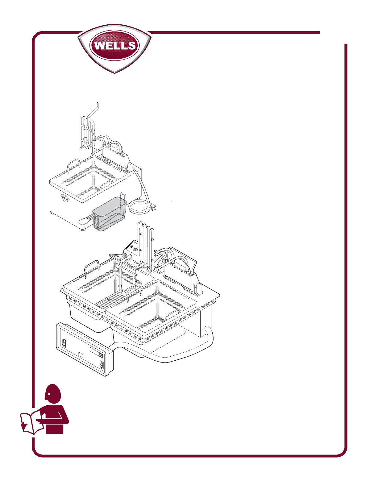
SUPPLEMENTAL
SERVICE
INSTRUCTIONS
for
STANDARD
FRYERS
Models
301
F-14 (LLF-14)
F-49
F-55, F-556
F-67, F-676
F-85, F-856
IMPORTANT: WELLS BLOOMFIELD PROPRIETARY INFORMATION.
DISSEMINATION OF THIS INFORMATION TO ANYONE OTHER THAN
WELLS AUTHORIZED SERVICE AGENTS IS STRICTLY PROHIBITED.
TECHNICAL CONTENT OF THIS MANUAL IS DESIGNED FOR
USE BY QUALIFIED PROFESSIONAL TECHNICIANS ONLY.
PRINTED IN UNITED STATES OF AMERICA
SV301 (new) Rev. (-) S301 080326 cps
Page 2
GENERAL
PRECAUTIONS AND GENERAL INFORMATION
WARNING:
RISK OF
Installation procedures must
be performed by a qualified
technician with full knowledge
of all applicable electrical and
plumbing codes. Failure can
result in personal injury and
property damage.
PERSONAL INJURY
WARNING:
ELECTRIC
All servicing requiring
access to non-insulated
electrical components must
be performed by a qualified
technician.
Only qualified technicians are
authorized to open any
access panel which requires
the use of tools. Failure to
follow this warning can result
in severe electrical shock.
SHOCK HAZARD
WARNING:
SEVERE BURN
HAZARD
Cooking oil is very hot and
can cause severe injury.
Avoid contact with hot oil.
Avoid spilling or splashing or
splattering hot oil.
CAUTION:
RISK OF
DAMAGE
DO NOT connect or
energize this appliance until
all installation instructions are
read and followed. Damage
to the appliance will result if
these instructions are not
followed.
This manual is considered to be Wells Bloomfield, LLC proprietary
information. Dissemination of this information to anyone other than
Wells Bloomfield authorized service agents is strictly prohibited.
Technical content of this manual, including any wiring diagrams,
schematics, parts breakdown illustrations and/or adjustment
procedures, is intended for use by qualified professional technicians
only.
This appliance is intended for use in commercial establishments
only.
This appliance is intended
No other use is
agents.
Operators of this appliance must be familiar with the appliance use,
limitations and associated restrictions. Operating instructions must be
read and understood by all persons using or installing this appliance.
Cleanliness of this appliance is essential to good sanitation. Read and
follow all included cleaning instructions and schedules to ensure the
safety of the food product.
Disconnect this appliance from electrical power before performing any
maintenance or servicing.
DO NOT submerge this appliance in water. Do not splash or pour
water on, in or over any controls, control panel or wiring.
Never use a wire brush or metal scraper on aluminum components.
Use bristle or fiber brush to clean pivots and other cast components.
Any procedure which requires the use of tools must be performed by a
qualified technician.
This appliance is made in the USA. Unless otherwise noted, this
appliance has American sizes on all hardware. Any conversion to
metric measurements are approximate and may vary.
Information in this manual reflects current production models as of
January 1, 2008. Specifications, model numbers, product numbers
and data subject to change without notice.
recommended or authorized by the manufacturer or its
to prepare food for human consumption.
SV301 Service Manual Standard Fryers
xi
Page 3
TABLE OF CONTENTS
Precautions & General Information …………………………… xi
General Information
Frypot Boil-Out ................................................................. 2
Disposing of Used Oil ....................................................... 3
Replacing Heating Elements ............................................ 4
Replacing Thermostats .................................................... 5
Replacing Fryhead Support Rod Spring .......................... 6
ID Chart - Thermostats & Knobs ..................................... 7
F-14 ....................................................................................... 8
F-49 ....................................................................................... 12
F-55, F-556 ........................................................................... 14
F-67, F-676 ............................................................................ 18
F-85, F-856 ............................................................................ 22
GENERAL
INTRODUCTION
This manual contains information needed to properly service and repair Wells standard fryers.
This manual applies to the following Wells Bloomfield models manufactured after Jan. 1, 2008:
F-14
F-49
F-55, F-556
F-67, F-676
F-85, F-856
SV301 Service Manual Standard Fryers
For units built after Jan. 1, 2008:
For installation, operation and maintenance instructions of countertop fryers, refer to Operation Manual
p/n 307588.
For, installation, operation and maintenance instructions of built-in fryers, refer to Operation Manual
p/n 307589.
For units built prior to Jan. 1, 2008:
For installation, operation and maintenance instructions of countertop fryers F-49, F-55ST D an d F-67,
refer to Operation Manual p/n 304355.
For installation, operation and maintenance instructions of countertop fryer LLF-14, refer to Operation
Manual p/n 45779.
For installation, operation and maintenance instructions of countertop fryers with safety test system,
F-55STS,and F-85 (including obsolete model F-101) refer to Operation Manual p/n 304356
For installation, operation and maintenance instructions of built-in fryers F-55STD and F-676, refer to
Operation Manual p/n 304359.
For installation, operation and maintenance instructions of built-in fryers with safety test system,
F-556STS, F-856, (including model F-1016) refer to Operation Manual p/n 304360.
1
Page 4
PERIODIC CLEANING
GENERAL
CAUTION:
BURN HAZARD
Be sure frypot and
elements are dry before
returning unit to service.
Water left in the frypot will
boil off when heating,
splattering hot oil.
CAUTION:
BURN HAZARD
Before cleaning, ALWAYS:
• Unplug the fryer and
allow to cool.
• Drain the oil and wipe
out the frypot.
Periodic cleaning is
necessary to remove
carbonization from the
elements and frypot.
Frypot may be cleaned by
the method described at
right, or with a commercial
frypot cleaner. Be sure to
follow the manufacturer's
directions.
PERIODIC CLEANING
Add 1/2 cup of granulated dishwasher detergent to frypot. Fill with water
to the MAX OIL line.
Lower the element into the frypot and set the control knob to 225ºF
Boil the mixture for five minutes. Turn the control knob to OFF. Allow the
mixture to set in the frypot overnight.
After the soak period, raise the elements and remove any remaining
carbonization with a stiff bristle brush. Be careful that the capillary tubes
of the thermobulbs are not moved or damaged during cleaning.
Drain the frypot and wash with warm water and mild detergent.
Reinstall the frypot in the fryer. Add 1 quart of vinegar, then fill to the MAX
OIL line with cold water.
Lower the elements into the vinegar solution. Allow to set for 15 minutes.
Drain the frypot and rinse with clean water. Dry the frypot and elements
thoroughly before returning the fryer to operation.
IMPORTANT:
Nickel plated frypot must be dried completely in order to prevent rusting,
and to eliminate water contamination of the cooking oil.
2
SV301 Service Manual Standard Fryers
Page 5
DISPOSAL OF USED OIL
DANGER: BURN HAZARD
Contact with hot oil will cause severe burns. Allow the fryer to cool before cleaning.
Always wear protective clothing and heat resistant gloves when handling hot oil.
PREPARATION Turn temperature control to OFF
Allow fryer to cool completely before draining
FREQUENCY Daily, or as needed
TOOLS Container for disposal of used oil.
OIL DISPOSAL
1. Turn temperature control to OFF.
2. Allow the oil to cool to a safe temperature (120ºF or 50ºC).
3. Raise the element head and lift the frypot out of the fryer by the
frypot handles.
4. Dispose of the used oil in an approved oil disposal receptacle, or
filter the oil for reuse.
5. Wipe the frypot and reinstall in the fryer.
Procedure is complete.
CAUTION:
BURN HAZARD
Allow fryer to cool completely
before draining.
CAUTION:
SLIP AND FALL
HAZARD
Clean up oil spills
immediately. Slipping in oil
can cause injury.
CAUTION:
HEALTH
Clean up oil spills
immediately. Oil provides an
environment for the growth of
bacteria, which presents a
health hazard.
HAZARD
GENERAL
SV301 Service Manual Standard Fryers
3
Page 6
REPLACE HEATING ELEMENT (all exc. F-14)
GENERAL
CAUTION:
BURN HAZARD
Allow fryer to cool before
performing this service.
CAUTION:
SHOCK HAZARD
Unplug fryer from electric
power before servicing.
IMPORTANT:
DO NOT damage the
capillary tubes. If the tubes
are pinched or kinked, they
are not repairable.
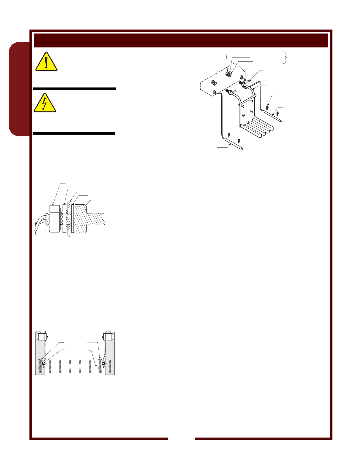
5/8-18 NUT
Element Attachment
IMPORTANT:
Be sure thermobulbs are
correctly seated in bulb clips.
These clips hold the bulbs
away from the element
surface. Failure to properly
position the clips will result in
the immediate failure of the
thermostat due to thermobulb
damage.
CAPILLARY CLIP
BULB CLIP
BULBS (ref)
ELEMENT
Cross-Section View of
Element and Thermobulbs
LOCK WASHER
CONTROL BOX
FIBER WASHER
ELEMENT
Element Assembly
5/8-18 NUT
LOCK WASHER
FIBER WASHER
CAPILLARY CLIP
6 places
ELEMENT
2 places
BULB CLIP
4 places
HI-LIMIT
BULB (ref)
TEMP
CONTROL
BULB (ref)
IMPORTANT: Unplug fryer and allow to cool before servicing.
A. REMOVE ELEMENT HEAD FROM FRYER
1. Remove two screws holding either element head pivot.
Remove pivot.
2. Lift element head assembly from fryer.
3. Remove bottom cover from control box.
B. DISCONNECT ELEMENT
1. Disconnect the wiring from the element terminals.
2. Note position of each thermobulb and the routing of the capillary
tubes. Remove bulbs from element by removing two bulb clips and
three capillary clips from each bulb.
3. Undo both holding nuts from terminal end of the element.
4. Withdraw the element from the control box.
C. INSTALL NEW ELEMENT
1. Wipe area around element openings in control box to remove any
grease or other cooking debris.
2. Slide one fiber washer over each end of the new element.
3. Insert element into the control box. Slide a lock washer over each
element, then thread on the holding nuts. Make sure the element
is square with the control box. Tighten holding nuts.
4. Reconnect wiring to the element terminals.
5. Reinstall the thermobulbs. Be sure a bulb clip is in place at each
end of the thermobulb.
NOTE: Control and HI-Limit thermobulbs may require different
bulb clips. Refer to parts list for proper component.
Snap a bulb clip over the element to secure the bulb. Carefully
route the capillary tube and secure with three capillary clips.
Repeat for both bulbs.
D. REINSTALL ELEMENT HEAD ON FRYER
1. For F-49, be sure the pivot washer is in place on the pivot brackets.
While holding the support rod in the forward position, slide the
element head assembly onto the fixed pivot. Reinstall the pivot
removed In step A.
Test fryer for proper operation and return to service.
SV301 Service Manual Standard Fryers
4
Page 7
REPLACE CONTROL OR HI-LIMIT THERMOSTAT (all exc. F-14)
REPLACE SPRING FOR FRYHEAD SUPPORT ROD
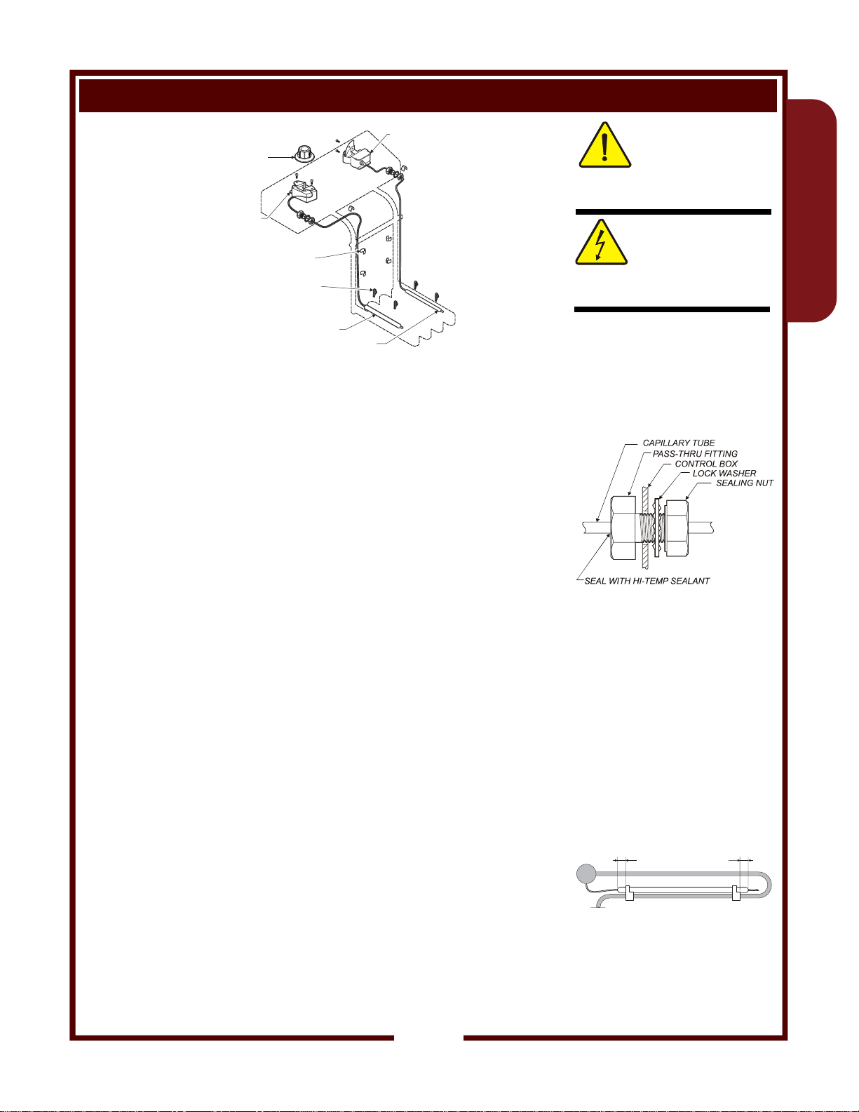
CONTROL
KNOB
HI-LIMIT
THERMOSTAT
Thermostat
Installation
TEMP
CONTROL
THERMOSTAT
CAPILLARY CLIP
6 places
TEMP CONTROL
THERMOSTAT BULB
BULB CLIP
4 places
HI-LIMIT THERMOBULB
Unplug fryer and allow to cool before servicing.
A. REMOVE ELEMENT HEAD FROM FRYER
Note: Some operations can be performed without removing the
fryhead. However, doing so will ease access to components and
fasteners.
1. Remove two screws holding either element head pivot.
Remove pivot.
2. Lift element head assembly from fryer.
3. Remove bottom cover from control box.
B. DISCONNECT THERMOSTAT
1. Remove the control knob if replacing the temperature control
thermostat.
2. Remove the two screws holding the thermostat to the control box.
3. Note the position of the wiring. Disconnect the wiring from the
thermostat terminals.
4. Note position of the thermobulb and the routing of the capillary
tube. Remove the bulb from the element by removing two bulb
clips and three capillary clips.
5. Undo the pass-thru fitting and withdraw the thermostat from the
control box.
SV301 Service Manual Standard Fryers
C. INSTALL NEW THERMOSTAT
1. Wipe area around pass-thru openings in control box to remove any
grease or other cooking debris.
2. Undo nut and lock washer from pass-thru fitting of the new
element. Insert the bulb from the inside of the control box.
3. Reconnect wiring to the thermostat terminals. Connect wiring then
attach the thermostat to the control box
4. Reinstall the thermobulbs. Slide two bulb clips over the bulb,
spacing the clips 3/8" from each end of the bulb. Snap the bulb
clips over the element, centering the bulb between element bends.
Carefully route the capillary tube and secure with three
capillary clips.
5. Carefully route capillary tube away from electrical terminals
inside of the control box. Tighten the pass-thru fitting then seal the
inside of the pass-thru fitting with hi-temp sealant.
D. REINSTALL ELEMENT HEAD ON FRYER (see page 4)
Test fryer for proper operation and return to service.
CAUTION:
BURN HAZARD
Allow fryer to cool before
performing this service.
CAUTION:
SHOCK HAZARD
Unplug fryer from electric
power before servicing.
IMPORTANT:
DO NOT damage the
capillary tubes. If the tubes
are pinched or kinked, they
are not repairable.
Capillary Tube Pass-Thru
Fitting
IMPORTANT:
Be sure bulb clips are
properly positioned on bulb,
and are clipped to element to
maintain the gap between
bulb and element. Failure to
properly position the rings will
result in the immediate failure
of the thermostat due to
thermobulb damage.
3/8"
Bulb Clip Spacing
3/8"
GENERAL
5
Page 8
REPLACE SPRING FOR FRYHEAD SUPPORT ROD
GENERAL
Allow fryer to cool before
performing this service.
CAUTION:
BURN HAZARD
CAUTION:
SHOCK HAZARD
Disconnect fryer from electric
power before servicing.
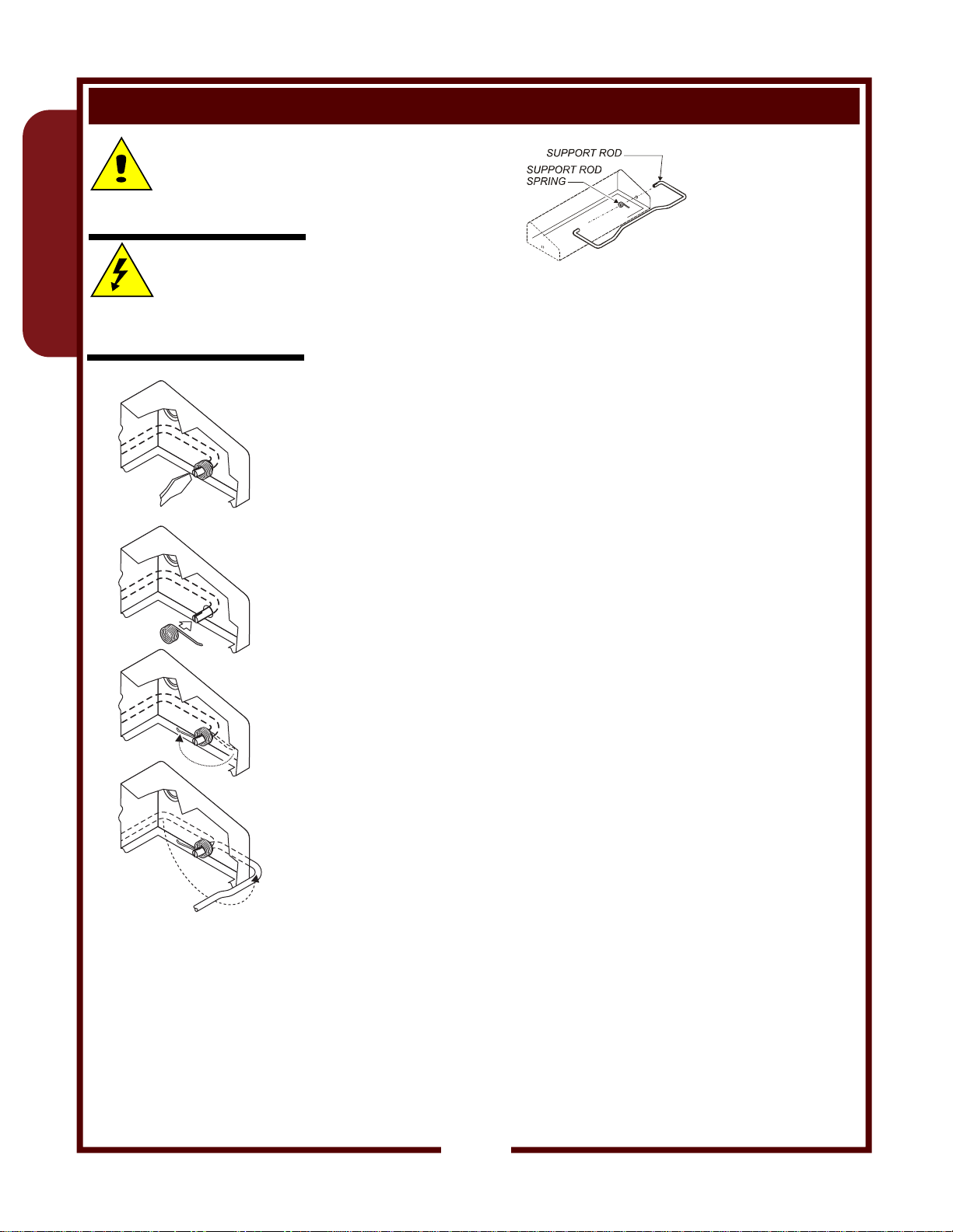
Installation Sequence
Support Rod
Spring Installation
Unplug fryer and allow to cool before servicing.
A. REMOVE ELEMENT HEAD FROM FRYER
Note: Some operations can be performed without removing the
fryhead. However, doing so will ease access to components and
fasteners.
1. Remove two screws holding either element head pivot.
Remove pivot.
2. Lift element head assembly from fryer.
3. Remove bottom cover from control box.
B. REMOVE BROKEN SPRING
1. Using a flat blade screwdriver or other suitable tool, pry the split
end of the support rod to open the slot.
2. Remove and discard the broken spring parts.
C. INSTALL NEW SPRING
1. Position the support rod toward the back (power cord) side of
the control box, then slide the new spring over the split end of
the support rod.
Note orientation: Long leg of spring at the top and pointing
toward the front; short leg of spring in the slot.
2. Using pliers, squeeze the split end of the support rod to capture
the spring.
3. Tension the spring by swinging the long leg clockwise, and
allowing it to rest against the lip of the control box.
D. REINSTALL ELEMENT HEAD ON FRYER
1. For F-14 and F-49, be sure the pivot washer is in place on the pivot
brackets. While holding the support rod in the forward position,
slide the element head assembly onto the fixed pivot. Reinstall the
pivot removed In step A
Test fryer for proper operation and return to service.
6
SV301 Service Manual Standard Fryers
Page 9
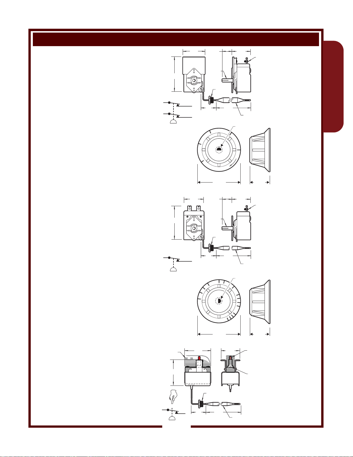
IDENTIFICATION CHART - THERMOSTATS AND CONTROL KNOBS
50133
THERMOSTATIC SWITCH
DPST - OPEN ON RISE
30AMP 240V
2.88
CAPILLARY & BULB
TEMP CONTROL
OFF - 200ºF TO 375ºF
F-14(LLF-14), F-49, F-55, F-67
COM1
COM2
T
54066
KNOB, TEMPERATURE CONTROL
THERMOSTAT
OFF (Bottom): 225ºF - 375ºF
Gray Plastic Knob / SS Skirt / Black Markings
Brushed Aluminum Center Insert
Fryer F-14( F-49, F-67LLF-14),
(WELLS)
55510
THERMOSTATIC SWITCH
SPST - OPEN ON RISE
30AMP 240V
CAPILLARY & BULB
TEMP CONTROL
OFF - 300ºF TO 375ºF
2.88
1.83
NC1
NC2
1.66
375
.25 DIA
SHAFT
20
325
WELLS
.25 DIA
SHAFT
.81
7/16-28
FERRULE
OFF
2.38”
.81
7/16-28
FERRULE
5.75
275
1.55
.38 DIA
BULB
8-32
SCREW
TERMINAL
(4 PLACES)
Æ.25” x .19”
225
1.13”
1.55
8-32
SCREW
TERMINAL
(2 PLACES)
GENERAL
F-55, F-85
COM1
T
SV301 Service Manual Standard Fryers
55511
KNOB, TEMPERATURE CONTROL
(WELLS)
THERMOSTAT
NC1
36
375
350
WELLS
8.50
.25 DIA
BULB
Æ.25” x .19”
325
OFF (Bottom): 300ºF - 375ºF
1.44
300
.25 DIA
BULB
1.13”
PUSH-BUTTON
RESET (RED)
8-32
SCREW
TERMINAL
(2 PLACES)
Gray Plastic Knob / SS Skirt / Black Markings
Brushed Aluminum Center Insert
Fryer F-55, F-85
FISH PAPER
58656
INSULATOR
THERMOSTATIC SWITCH
SPST - OPEN ON RISE
440ºF ±15ºF 30AMP 240V
2.13
CAPILLARY & BULB
HI-LIMIT SAFETY w/
MANUAL RESET
F-14(LLF-14), F-49, F-55,
F-67, F-85
RESET
COM1
T
NC1
2.16
24
OFF
2.38”
7/16-28
FERRULE
5.0
7
Page 10

COUNTERTOP FRYER F-14
Allow fryer to cool before
performing this service.
F-14
Unplug fryer from electric
power before servicing.
IMPORTANT:
DO NOT damage the
capillary tubes. If the tubes
are pinched or kinked, they
are not repairable.
F-14 Element Attachment
IMPORTANT (F-14):
Be sure wire rings are in
place on thermobulbs. Rings
must be positioned between
the bulb clips. Failure to
properly position the rings will
result in the immediate failure
of the thermostat due to
thermobulb damage.
Cross-Section View of F-14
Elements
CAUTION:
BURN HAZARD
CAUTION:
SHOCK HAZARD
REPLACE ELEMENT (F-14)
Element Assembly
(F-14)
IMPORTANT: Unplug fryer and allow to cool before servicing.
A. REMOVE ELEMENT HEAD FROM FRYER
1. Remove two screws holding either element head pivot.
Remove pivot.
2. Lift element head assembly from fryer.
3. Remove bottom cover from control box.
B. DISCONNECT ELEMENT
1. Remove the handle and clamps from the element.
2. Disconnect the wiring from the element terminals.
3. Note position of each thermobulb and the routing of the capillary
tubes. Remove bulbs from element by removing two bulb clips and
three capillary clips from each bulb.
4. Undo both holding nuts from terminal end of the element.
5. Withdraw the element from the control box.
C. INSTALL NEW ELEMENT
1. Wipe area around element openings in control box to remove any
grease or other cooking debris.
2. Slide one fiber washer over each end of the new element.
3. Insert element into the control box. Slide a lock washer over each
element , then thread on the holding nuts. Make sure the element
is square with the control box. Tighten holding nuts.
4. Reconnect wiring to the element terminals.
5. Reinstall the thermobulbs. Be sure the wire ring is intact and in
place at each end of the thermobulb. Snap a bulb clip over the
element and over each end of bulb to secure the bulb to the
element. The wire rings must be between the bulb clips. Carefully
route the capillary tube and secure with three capillary clips.
Repeat for both bulbs.
6. Reinstall handle and clamps.
D. REINSTALL ELEMENT HEAD ON FRYER
1. Be sure the pivot washer is in place on the pivot brackets.
While holding the support rod in the forward position, slide the
element head assembly onto the pivot. Reinstall the pivot
removed In step A.
Test fryer for proper operation and return to service.
SV301 Service Manual Standard Fryers
8
Page 11

COUNTERTOP FRYER F-14
REPLACE CONTROL OR HI-LIMIT THERMOSTAT (F-14)
Thermostat
Installation
Unplug fryer and allow to cool before servicing.
A. REMOVE ELEMENT HEAD FROM FRYER
1. Remove two screws holding either element head pivot.
Remove pivot.
2. Lift element head assembly from fryer.
3. Remove bottom cover from control box.
B. DISCONNECT THERMOSTAT
1. Remove the control knob if replacing the temperature control
thermostat.
2. Remove the two screws holding the thermostat to the control box.
3. Note the position of the wiring. Disconnect the wiring from the
thermostat terminals.
4. Note position of the thermobulb and the routing of the capillary
tube. Remove the bulb from the element by removing two bulb
clips and three capillary clips.
5. Undo the pass-thru fitting and withdraw the thermostat from the
control box.
C. INSTALL NEW THERMOSTAT
1. Wipe area around pass-thru openings in control box to remove any
SV301 Service Manual Standard Fryers
grease or other cooking debris.
2. Undo nut and lock washer from pass-thru fitting of the new
element. Insert the bulb from the inside of the control box.
3. Reconnect wiring to the thermostat terminals. Connect wiring then
attach the thermostat to the control box
4. Reinstall the thermobulbs. Be sure the wire spacing rings are
intact and in place at each end of the thermobulb. Snap a bulb clip
over the element and over each end of bulb to secure the bulb to
the element. The wire spacing rings must be between the bulb
clips. Carefully route the capillary tube and secure with three
capillary clips.
5. Carefully route capillary tube away from electrical terminals
inside of the control box. Tighten the pass-thru fitting then seal the
inside of the pass-thru fitting with hi-temp sealant.
D. REINSTALL ELEMENT HEAD ON FRYER (see page 8)
Test fryer for proper operation and return to service.
Allow fryer to cool before
performing this service.
CAUTION:
BURN HAZARD
CAUTION:
SHOCK HAZARD
Unplug fryer from electric
power before servicing.
IMPORTANT:
DO NOT damage the
capillary tubes. If the tubes
are pinched or kinked, they
are not repairable.
Capillary Tube Pass-Thru
Fitting
IMPORTANT:
Be sure wire rings are in
place on thermobulbs. Rings
must be positioned between
the bulb clips. Failure to
properly position the rings will
result in the immediate failure
of the thermostat due to
thermobulb damage.
F-14 Thermobulb Installation
F-14
9
Page 12

COUNTERTOP FRYER F-14
F-14
temp control
51157
red
54066
50516
amber
50133
65725
(120V)
shown
65729
(240V)
similar
65777
50792
65774
55747
53436
(pk 2)
58667
58656
hi-limit
58667
55736
(pk 10)
KEPS green
18-302
52428
52427
65777
55637
65061 (120V )
20141 (240V )
5-15P
6-30P
65788 (120V)
50789 (240V)
65783
kit: handle &
front clamp assy
65784
kit: rear clamp assy
21056
65767
55566
(pk 100)
65765
51053
(pk 100)
65728
(pk 4)
55028
53890
(pk 10)
20169
53848
SV301 Service Manual Standard Fryers
10
Page 13

POWER CORD
COUNTERTOP FRYER F-14
THERMOSTAT
HI-LIMIT
THERMO
SIGNAL
LITE
CONTROL
HEATING
ELEMENT
WIRE NUT
(50/60 HZ)
TEMP
LITE
VOLTS
120
208
240
RELAY
HI-LIMIT
THERMO
COIL
NO
C
FRYER F-14
AMPS
1 PHASE
15.0
16.3
18.8
WIRE NUT
F-14
L1
SV301 Service Manual Standard Fryers
HI-LIMIT
THERMO
T
CONTACT SET 1
TEMP CONTROL
WIRE NUT
LITE
TEMP
RELAY
HI-LIMIT
L2
CONTACT SET 2
TEMP CONTROL
TT
C
LITE
SIGNAL
HEATING
ELEMENT
WIRE NUT
WIRING DIAGRAM F-14 (LLF-14) p/n 307306
11
Page 14

COUNTERTOP FRYER F-49
50516
51157
58656
F-49
amber
red
hi-limit
62504
(pk 4)
54452
50176
50177
(pk 10) lock washer
50172
fiber washer
nut
50157
RESET
50157
52482
54066
50133
temp control
62891 (208V)
62892 (240V)
53436
53435
53890
(pk 10)
HEAD ASSY COMPLETE, F-49
62899 (208V)
62900 (240V)
63665
(pk 10)
20161
1/2 size
20162
full size
55566
(pk 100)
54323 51206
54206
20314 plastic
20563 metal
(pk 4)
55736
(pk 10)
KEPS green
52427
51208
51207
(pk 4)
20169
53848
SV301 Service Manual Standard Fryers
22728
50789
12
Page 15

POWER CORD
CONTROL
THERMOSTAT
COUNTERTOP FRYER F-49
RELAY
HI-LIMIT
THERMO
WIRE NUT
HI-LIMIT
THERMO
SIGNAL
L1
LITE
WIRE NUT
HEATING
ELEMENT
TEMP
LITE
FRYER F-49
VOLTS
(50/60 HZ)
208/240
208
COIL
C
208
240
NO
WIRE NUT
F-49
AMPS
1 PHASE
16.6
19.1
22.1
L2
SV301 Service Manual Standard Fryers
LITE
SIGNAL
RELAY
HI-LIMIT
LITE
TEMP
C
CONTACT SET 1
TEMP CONTROL
WIRE NUT
T
HI-LIMIT
THERMO
WIRE NUT
HEATING
ELEMENT
WIRE NUT
CONTACT SET 2
TEMP CONTROL
TT
WIRING DIAGRAM F-49 p/n 307298
13
Page 16

COUNTERTOP FRYER F-55
50516
51157
58656
hi-limit
62504
54452
F-55(6)
50176
amber
red
53068
(pk 4)
50177
(pk 10) lock washer
50172
50464
fiber washer
nut
50157
RESET
50157
52428
52427
55511
55510
temp control
62504
(pk 4)
62842 (208V)
62866 (240V)
53890
(pk 10)
52806
51717
(pk 40)
HEAD ASSY COMPLETE, F-55
62903 (208V)
62904 (240V)
20161
1/2 size
20162
full size
20169
50183
55028
55566
(pk 100)
20314 plastic
20563 metal
(pk 4)
22728
50789
51206
OPTIONAL
51208
51207
(pk 4)
51053
(pk 100)
53068
54005
55736
(pk 10)
KEPS green
50131
61974
53848
(pk 10)
SV301 Service Manual Standard Fryers
14
Page 17

BUILT-IN FRYER F-556
50516
amber
51157
red
58656
hi-limit safety
53068
50464
50176
54452
50177
lock washer
50172
fiber washer
(pk 10)
nut
62504
(pk 4)
RESET
50157
52428
52427
55511
55510
temp control
62842 (208V)
62866 (240V)
53890
62504
(pk 4)
(pk 10)
51717
52806
HEAD ASSY, COMPLETE, F-556
62903 (208V)
62904 (240V)
20161
20162
(pk 40)
1/2 size
full size
20169
F-55(6)
51208
51207
(pk 4)
50183
SV301 Service Manual Standard Fryers
55028
55566
(pk 100)
51206
55736
(pk 10)
green KEPS
53068
54005
50131
61974
(pk 10)
51053
(pk 100)
15
Page 18

COUNTERTOP FRYER F-55 and BUILT-IN FRYER F-556
F-55(6)
TERMINAL BLOCK
L2
L1
CONTROL
THERMOSTAT
HI-LIMIT
THERMO
SIGNAL
LITE
WIRE NUT
TERMINAL BLOCK
FLAME SENSOR
REMOVE JUMPER WHEN
EXTERNAL CONTROL USED
IMPORTANT:
DO NOT CONNECT ANY POWER TO
FLAME SENSOR TERMINAL BLOCK
RELAY
HI-LIMIT
THERMO
COIL
NO
C
WIRE NUT
TEMP
LITE
HEATING
ELEMENT
FRYER F-55 and F-556
VOLTS
(50/60 HZ)
208
240
WIRING DIAGRAM F-55 and F-556 p/n 307309
16
AMPS
1 PHASE
27.6
24.0
SV301 Service Manual Standard Fryers
Page 19

COUNTERTOP FRYER F-55 and BUILT-IN FRYER F-556
L1
LITE
TEMP
RELAY
HI-LIMIT
C
LITE
SIGNAL
L2
T
FLAME SENSOR JUMPER
OR EXTERNAL CONTROL
HI-LIMIT
THERMO
HEATING
CONTACT SET 2
TEMP CONTROL
TT
WIRE NUT
SV301 Service Manual Standard Fryers
ELEMENT
WIRE NUT
WIRING SCHEMATIC F-55 and F-556
CONTACT SET 1
TEMP CONTROL
F-55(6)
17
Page 20

COUNTERTOP FRYER F-67 and BUILT-IN FRYER F-676
HEAD ASSY COMPLETE
F-67(6)
NOTE: Unit has two identical
fryer heads. Only one is shown
50516
51157
50177
50176
amber
red
fibre washer
(pk 10 ) lock washer
50172
nut
62916 (240V)
54066
(208V)62915
50133
temp control
F-67(6)
58656
54452
hi-limit
62504
(pk 4)
50157
RESET
50157
62891 (208V)
62892 (240V)
52428
52427
51208
51207
(pk 4)
51206
63665
(pk 10)
54323
55566
(pk 100)
50183
53245
18
53895
53890
51717
52806
(pk 10)
(pk 40)
SV301 Service Manual Standard Fryers
Page 21

COUNTERTOP FRYER F-67 and BUILT-IN FRYER F-676
53068
F-67 CABINET
COMMON
COMPONENTS
20314
20563
plastic
metal(pk 4)
54005
50131
61947
(pk 10)
55736 (pk 10)
green KEPS
51053
53848
(pk 100)
20169
SV301 Service Manual Standard Fryers
20161 1/2 size
20162 full size
55736
green KEPS
(pk 10)
19
F-67(6)
53068
54005
50131
61974
(pk 10)
F-676 CABINET
Page 22

COUNTERTOP FRYER F-67 and BUILT-IN FRYER F-676
TERMINAL BLOCK
TERMINAL BLOCK
(3 PHASE)
L1 L1
L2 L2
L3 L3
1 1
1 1
2
2
CONTROL
THERMOSTAT
CONTROL
THERMOSTAT
RELAY
HI-LIMIT
HI-LIMIT
THERMO
WIRE
NUT
THERMO
COIL COIL
NO NO
CC
WIRE
NUT
HI-LIMIT
THERMO
WIRE
NUT
(1 PHASE)
RELAY
HI-LIMIT
THERMO
2
2
WIRE
NUT
F-67(6)
FRYER F-67 and F-676
VOLTS
(50/60 HZ)
208/240V
VOLTS
(50/60 HZ)
208/
240V
208
SIGNAL
208
240
208
AMPS 3 PHASE
L1 L2 L3
208
28.8
240
33.2
38.3
LITE
AMPS
1 PHASE
33.2
38.3
44.2
16.6
19.2
22.1
16.6
19.2
22.1
TEMP
LITE
HEATING
ELEMENT
SIGNAL
LITE
TEMP
LITE
HEATING
ELEMENT
WIRING DIAGRAM F-67 and F-676 p/n 307302
SV301 Service Manual Standard Fryers
20
Page 23

COUNTERTOP FRYER F-67 and BUILT-IN FRYER F-676
L1 L2 L3
LITE
SIGNAL
T
HI-LIMIT
THERMO
CONTACT SET 1
TEMP CONTROL
T
CONTACT SET 2
TEMP CONTROL
T
LITE
TEMP
HEATING
ELEMENT
RELAY
HI-LIMIT
C
WIRE NUT
WIRE NUT
LITE
SIGNAL
LITE
TEMP
RELAY
HI-LIMIT
C
T
SV301 Service Manual Standard Fryers
HI-LIMIT
THERMO
HEATING
CONTACT SET 2
TEMP CONTROL
T
WIRE NUT
ELEMENT
WIRE NUT
WIRING SCHEMATIC F-67 and F-676
CONTACT SET 1
TEMP CONTROL
T
FOR SINGLE PHASE
CONNECT TOL2
F-67(6)
21
Page 24

COUNTERTOP FRYER F-85 and BUILT-IN FRYER F-856
HEAD ASSY COMPLETE, F-85
NOTE: Unit has two identical
fryer heads. Only one is shown
62903
62904 (240V)
(208V)
50516
51157
red
58656
54452
50176
amber
hi-limit
50177
fibre washer
(pk 10 ) lock washer
50172
nut
50157
62504
(pk 4)
RESET
55511
55510
50157
62891 (208V)
62892 (240V)
52428
52427
temp control
51208
51207
62504
(pk 4)
(pk 4)
F-85(6)
54323
55566
(pk 100)
(typical)
50183
53245
53895
22
53890
(pk 10)
51717
(pk 40)
52806
51206
SV301 Service Manual Standard Fryers
Page 25

COUNTERTOP FRYER F-85 and BUILT-IN FRYER F-856
F-85 CABINET
51053
(pk 100)
57779 (208V)
57780 (240V)
20314
20563
F-856 CABINET
plastic
metal
(pk 4)
53068
54005
50131
55736
green KEPS
(pk 10)
55127
61974
(pk 10)
53848
20161
1/2 size
20162
full size
COMMON
COMPONENTS
53068
54005
SV301 Service Manual Standard Fryers
50131
61974
(pk 10)
51053
(pk 100)
20169
F-85(6)
57779(208V)
57780(240V)
51881
sleeve (requires 3')
53848
55127
23
Page 26

COUNTERTOP FRYER F-85 and BUILT-IN FRYER F-856
LEFT
HEATING
ELEMENT
TEMP LIGHT
(AMBER)
CONTROL
THERMOSTAT
13
CONTACTOR
C
14
HI-LIMIT
T'STAT
15
9
TROUBLE
LIGHT (RED)
20
C
50
21
19
16
17
CONTACTOR
18
RIGHT
HEATING
ELEMENT
TEMP LIGHT
(AMBER)
CONTROL
THERMOSTAT
2222 2323
1
CONTACTOR
C
5251
2
HI-LIMIT
T'STAT
3
TROUBLE
LIGHT (RED)
212121
20
CONTACTOR
C
1010 77
50
*REMOVE JUMPER WHEN
EXTERNAL CONTROL IS
USED.
IMPORTANT:
DO NOT CONNECT ANY
POWER TO FLAME
SENSOR TERMINAL
BLOCK!
FLAME SENSOR
25
TERMINAL BLOCK*
19
TERMINAL
26
BLOCK
L1
L2
L3
6
4
5
GROUND
1212 9
1111 88
F-85(6)
VOLTS
50/60 HZ
WIRING DIAGRAM F-85 p/n 307495
208
240
POWER
SWITCH
WITH
LIGHT
25
27
3 PHASE AMPS PER LEG
L1 L2 L3
31.9
31.9 31.9
27.6 27.6 27.6
1 PHASE
AMPS
47.9
19
13
27
5
15
14
18
1
SINGLE PHASE
CONFIGURATION
2
4
16
19
3
6
17
26
TERMINAL
BLOCK
GROUND
L1
L2
SV301 Service Manual Standard Fryers
24
Page 27

COUNTERTOP FRYER F-85 and BUILT-IN FRYER F-856
L1 L2 L3
HEATING ELEMENT
TEMP LIGHT
T
HI-LIMIT T'STAT
T
TROUBLE LIGHT
SV301 Service Manual Standard Fryers
HI-LIMIT T'STAT
T
TROUBLE LIGHT
C
CONTACTOR
C
CONTACTOR
CONTROL T'STAT
HEATING ELEMENT
TEMP LIGHT
CONTROL T'STAT
T
C
CONTACTOR
C
CONTACTOR
POWER
SWITCH
JUMPER
OR
EXTERNAL
CONTROL
F-85(6)
WIRING SCHEMATIC F-85 and F-856 - 3 PHASE
25
 Loading...