

Page 1
© 1987 McDonald's Corporation Printed in November Printed in All Rights Reserved
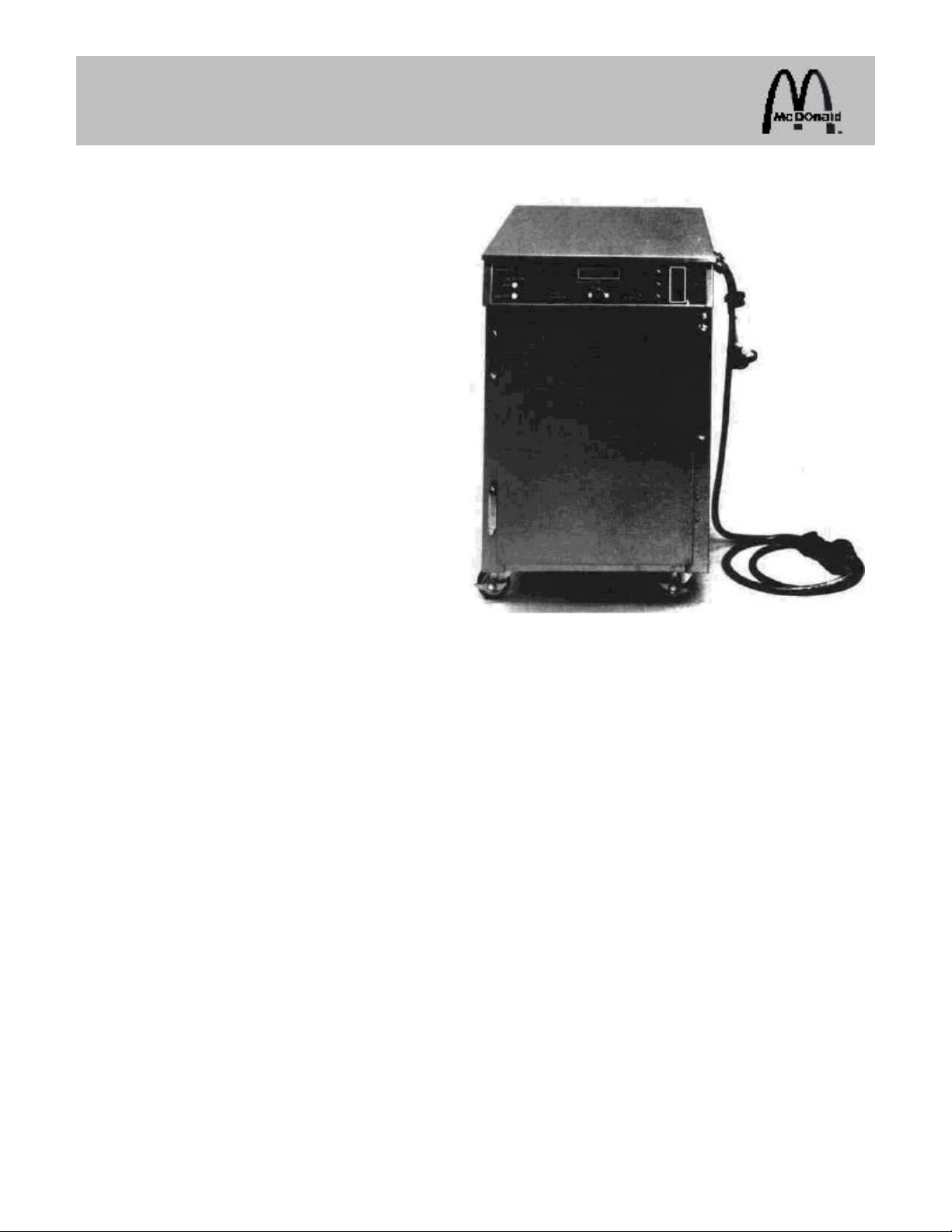
DUAL ACCESS BISCUIT CABINET
WELLS MODELS DABC-1PS
and DABC-1TL
This equipment chapter is to be placed in the Holding Cabinets Section of the Equipment Manual.
MANUFACTURED EXCLUSIVELY FOR
McDONALD'S
BY
WELLS MANUFACTURING
2 ERIK CIRCLE VERDI, NEVADA 89439
PHONE: 1 (702) 345-0444
TOLL FREE: 1 (800) 777-0450
FAX #: 1 (702) 345-0569
TABLE OF CONTENTS
WARRANTY......................................................................................................................... Page 2
INTRODUCTION.................................................................................................................. Page 2
SAFETY................................................................................................................................ Page 2
PARTS IDENTIFICATION/FUNCTION/PHOTOS..............................................................Page 3
HARDWARE IDENTIFICATION........................................................................................Page 19
EQUIPMENT SET UP AND CLOSE PROCEDURES .....................................................Page 20
TROUBLESHOOTING....................................................................................................... Page 22
PARTS ORDERING/SERVICE INFORMATION.............................................................. Page 24
NON-SCHEDULED MAINTENANCE.................................................. ...........................Page 24
WIRING PICTORIAL ..........................................................................................................Page 36
WIRING DIAGRAM............................................................................................................Page 38
This manual is for the exclusive use of licensees and employees of McDonald's Systems, Inc.
Reprinted in April, 1989 The United States of America
Page 2
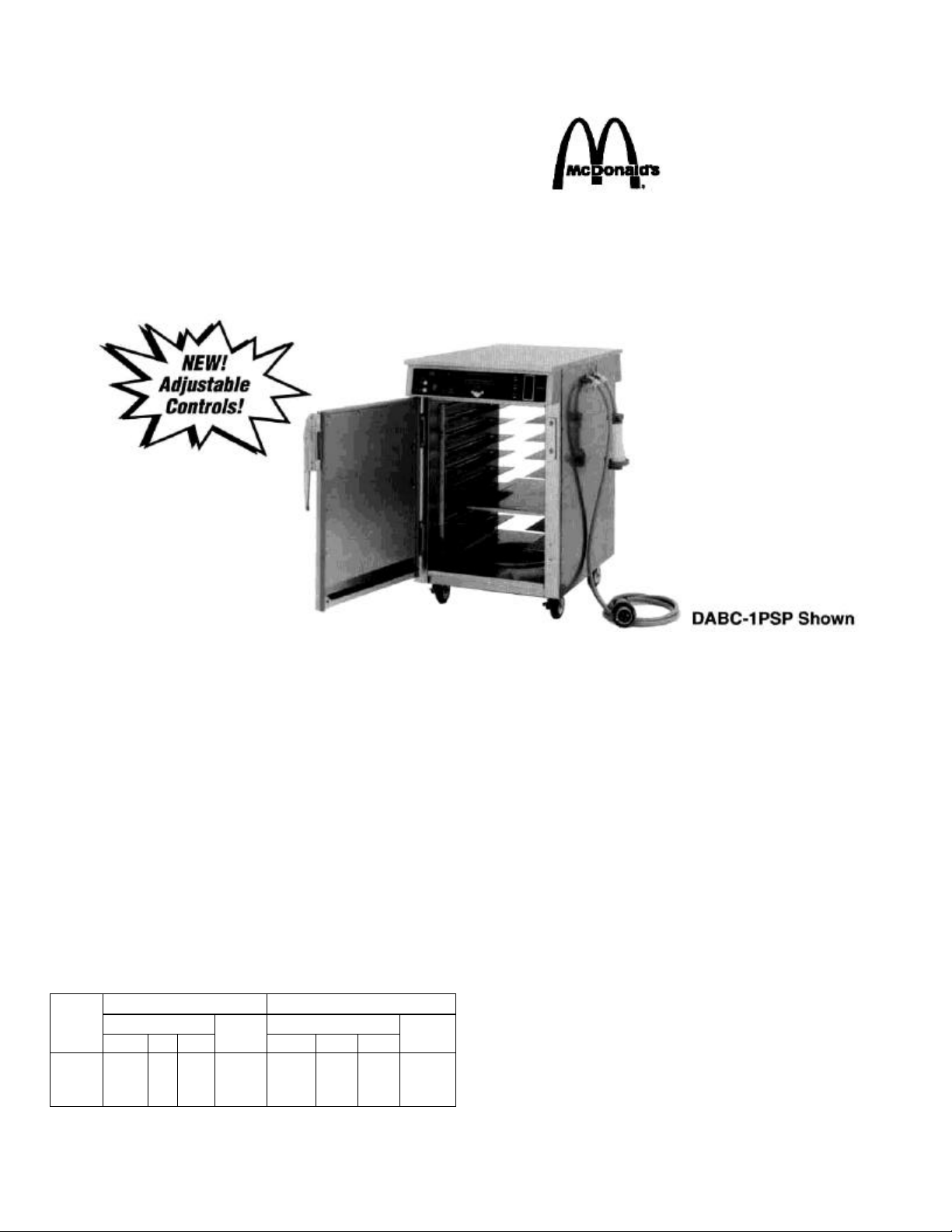
DUAL ACCESS BISCUIT CABINET
Models DABC-1PSP and DABC-1TL
PRODUCT FEATURES
• Fully adjustable water and air temperatures.
• Front and rear doors allow loading and unloading from either end for
efficient workflow.
• Adjustable solid-state electronic thermostat senses and displays
accurate temperature.
• Built-in three channel timer displays that can be operated from both
front and back of unit.
• Signal light located on both front and rear to indicate that opposite
door is open.
• Audible and visual low water indicator.
• Heat ON indicator lights for both air and water.
• LED digital temperature display (F or C) for air or water - select by
switch.
• Easy to clean water pan with one multi-function probe for low water
level and temperature.
• All stainless steel construction.
• Cabinet designed for floor installation. Shipped with casters.
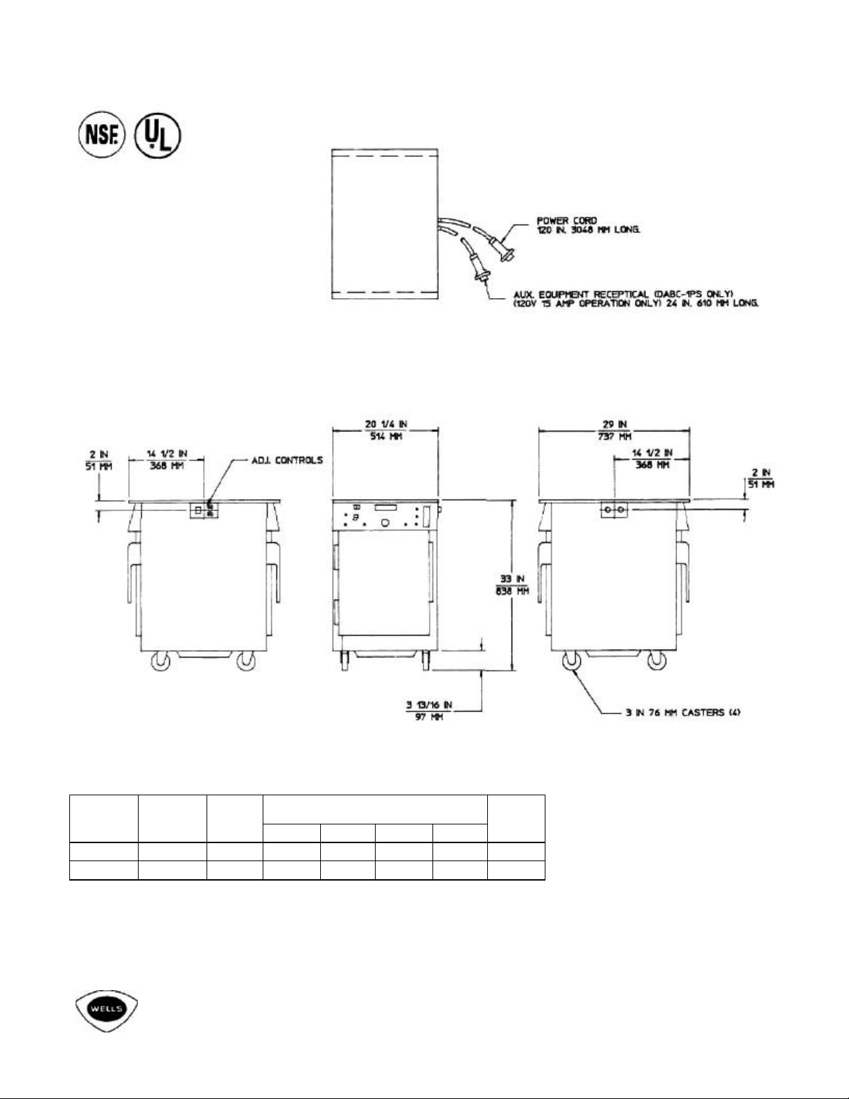
DIMENSIONS
INSTALLED SHIPPING
MODELS
DABC1PSP
DABC1TL
DIMENSIONS DIMENSIONS
W D H
20 1/4" 29" 33" 175 27 3/8" 33 3/4" 36 1/8” 204
WEIGHT
W D H
WEIGHT
ELECTRICAL INFORMATION
Model DABC-1PSP:
Voltage: 208V, three phase, four wire. Power: 1. 1 KW, for amperage
refer to table on reverse side. Cabinet is provided with a 10-foot cord
with pin-and-sleeve connector for power, and a 2-foot cord with pinand-sleeve auxiliary receptacle for 15 amp, 120V unit only.
Model DABC-1TL: (Replacement only)
Voltage: 120V, single phase.
Power: 1. 1 KW, for amperage refer to table on reverse side. Cabinet
is provided with a 10-foot cord with a NEMA L5-20P twist-lock for
power and NO auxiliary appliance connection.
PRODUCT FINISH
Stainless steel top. front, sides and back.
PRODUCT WARRANTY
The DABC-1PSP and DABC-1TL Dual Access Biscuit Cabinets
manufactured by Wells are warranted to be free from defects in
materials and workmanship for a period of one year from the date of
original installation and is for the benefit of the original purchaser only.
This warranty does not apply to damage resulting from fire, water,
burglary, accident, abuse, misuse, acts of God, faulty installation
including improper electrical supply.
THIS WARRANTY IS THE COMPLETE AND ONLY
WARRANTY, THERE BEING NO OTHER
WARRANTIES, EXPRESSED OR IMPLIED IN LAW OR
IN FACT, INCLUDING BUT NOT LIMITED TO,
WARRANTIES OF MERCHANT-ABILITY OR FITNESS
FOR ANY PARTICULAR PURPOSE, AND/OR FOR
DIRECT, INDIRECT. OR INCONSEQUENTIAL
DAMAGES IN CONNECTION WITH WELLS'
PRODUCTS.
Wells' obligation under this warranty is limited to the repair of defects
or replacement without charge by a WELLS factory authorized service
agency or one of its sub-service agencies. This service will be
provided on customer's premises.
Page 3
DUAL ACCESS BISCUIT CABINET
Models DABC-1PSP and DABC-1TL
ELECTRICAL SPECIFICATIONS
AMPS PER LINE THREE PHASE MODEL VOLTS KW
LI L2 L3 N
DABC-1PSP 208 1. 1 10 15 - 25 -
DABC-1TL 120 1. 1 - - - - 8. 8
NOTE: 4 WIRE 3 PHASE L3 NOT USED
AMPS
SINGLE
PHASE
Wells Manufacturing Company
2 Erik Circle, P. O. Box 280 • Verdi, NV 89439
(702) 345-0444 • FAX: 702-345-0569 TOLL-FREE
FAX: 800-356-5142, for orders only
1994 Wells Manufacturing Company Printed in U. S. A. Item No. 43958 B
Page 4

WARRANTY STATEMENT
The Dual Access Biscuit Cabinet manufactured by
Wells is warranted to be free from defects in materials
and workmanship for a period of one year from the date
of original installation and is for the benefit of the
original purchaser only, BUT NOT AGAINST DAMAGE
CAUSED BY ABUSE, FAULTY INSTALLATION,
INCLUDING IMPROPER ELECTRICAL CURRENT.
THIS WARRANTY IS THE COMPLETE AND ONLY
WARRANTY, THERE BEING NO OTHER WARRANTIES, EXPRESSED OR IMPLIED IN LAW OR IN
FACT, INCLUDING BUT NOT LIMITED TO,
WARRANTIES OF MERCHANT ABILITY OR FITNESS
FOR ANY PARTICULAR PURPOSE, AND/OR FOR
DIRECT, INDIRECT OR CONSEQUENTIAL
DAMAGES IN CONNECTION WITH WELLS
PRODUCTS.
Wells' obligation under this warranty is limited to the
repair of defects or replacement without charge by a
WELLS factory authorized service agency or one of its
sub-service agencies. This service will be provided on
customer's request.
Please contact the Service Department: Wells
Manufacturing Company, P. O. Box 280, Verdi, Nevada
89439; to arrange service or for additional information
and other details concerning the product and/or this
warranty.
INTRODUCTION
The commercial Dual Access Biscuit Cabinet is
designed to hold food at a desired serving temperature
and moistness plus allow access to the food product
from either the front or the rear of the cabinet. Both
models have built-in 3 channel product timers that can
be activated from either the front or the rear of the
cabinet.
The Model DABC-1 PS is configured with an IEC 309
Pin & Sleeve plug and connector for the main power
and auxiliary device connection.
WARNING: The DABC-1 PS operates on 120 VAC.
The power connection has been designed for 208 VAC,
3-Phase-Y, 5-wire, 120/208 split, such that two
independent 120 VAC inputs are supplied to the unit.
The auxiliary connection is 120 VAC at 15 amp
maximum for other appliances, i. e. Marinator Model
MDMW-3.
The Model DABC-1TL is configured with a NEMA L520P twist-lock for the power supply connection and NO
auxiliary appliance connection is provided.
SAFETY
Knowledge of proper installation, operation and
maintenance procedures is essential to ensure safe
operation of any equipment. The instructions contained
herein are meant as guidelines; major considerations to
be kept in mind are:
1. Always have dry hands prior to turning the power
switch ON or OFF.
2. Turn OFF the power switch anytime the cabinet is
not in use.
3. If an electric shock is felt when touching the
cabinet, disconnect the power immediately and
call Wells Service Department for assistance and
service.
4. Have the electrical power installed by a licensed
electrician. Make sure that the equipment is
properly grounded.
5. If you find that the electrical cord is frayed, DO
NOT PLUG IT INTO THE ELECTRICAL POWER
RECEPTACLE. IF IT IS ALREADY PLUGGED
IN, DISCONNECT THE PLUG AFTER
SHUTTING OFF THE CIRCUIT BREAKER.
6. DISCONNECT THE POWER CORD BEFORE
ATTEMPTING ANY REPAIRS AND/OR
CLEANING THE UNIT WITH WATER.
7. Allow the unit to cool before cleaning.
8. DON'T EVER SPLASH WATER WITH A HOSE
OR OTHERWISE ONTO THE UNIT. WET
ELECTRICAL COMPONENTS AND WIRING
PRESENT A HIGH SHOCK HAZARD.
9. Follow the cleaning procedures described on the
Biscuit Cabinet (Wells) Planned Maintenance
System Card #64.
CAUTION: DO NOT OPERATE THE UNIT UNLESS
ALL FOUR CASTERS ARE INSTALLED. THE UNIT IS
SHIPPED WITH THE CASTERS IN PLACE AND
THEY SHOULD NOT BE REMOVED. PERSONAL
INJURY AND DAMAGE TO THE UNIT MAY RESULT.
2
Page 5
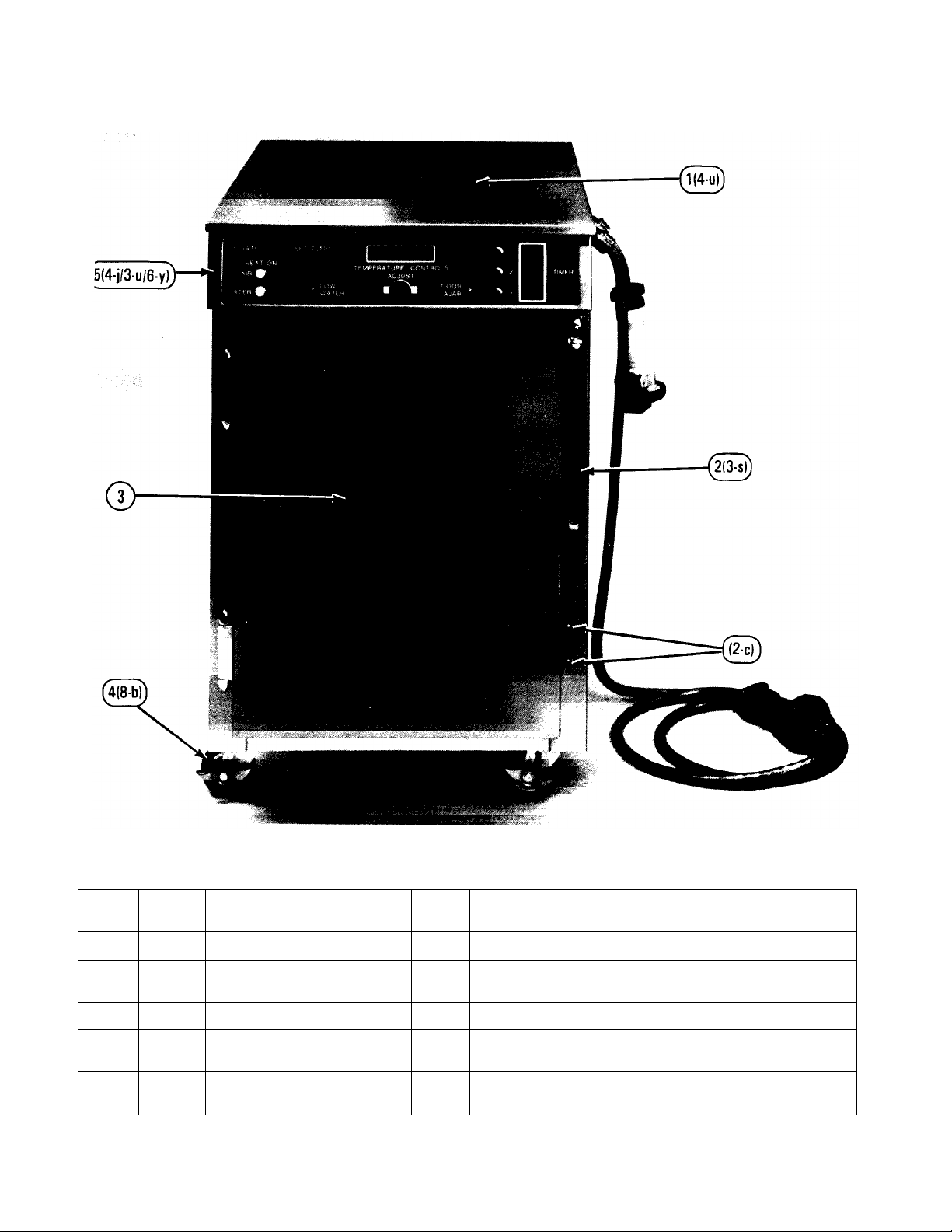
PARTS IDENTIFICATION/FUNCTION/PHOTOS
(DABC-1PS Shown, DABC-1TL Same except as noted)
ITEM
PART
NO.
1 62385 Outer Cabinet Top 1 Covers and protects the controls, wiring and components.
2 63045 Front Door Handle 1 Provides access to the unit and secures the door when
3 62391 Front Door Wrap 1 Provides an exterior cover for the cavity door assembly.
4 63042 Swivel Wheel with Brake 2 Allows the unit to be moved about and secures it in place
5 63425 Front Control Panel Sub-
DESCRIPTION QTY. FUNCTION
closed.
when stationary.
1 Used to mount electrical control components.
Assembly
3
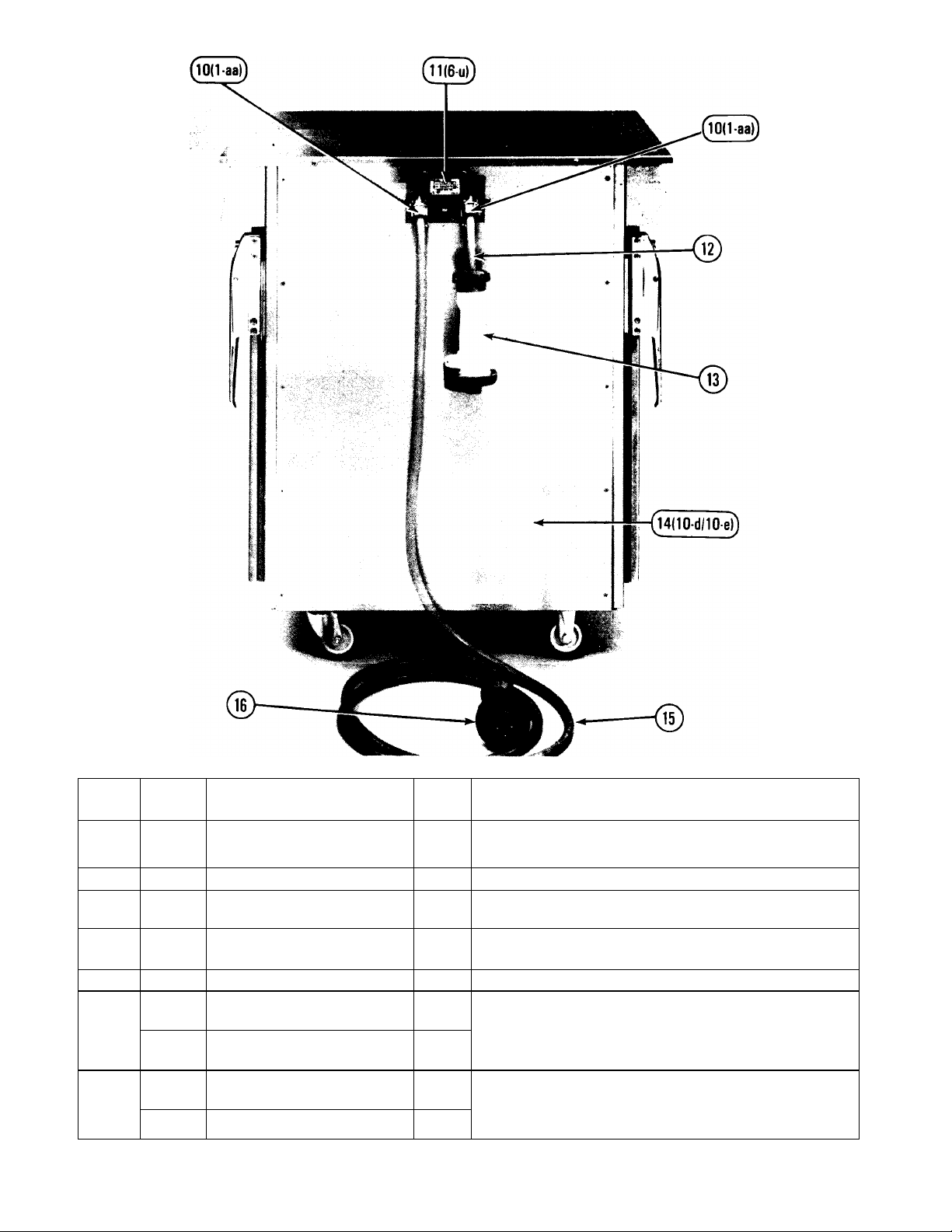
Page 6
ITEM
PART
NO.
10 62405 Cord Strain Relief
11 62378 Electric Conversion Panel 1 Attaches plug/connector assemblies to the unit.
12 56307 Cord 14/3 STO (DABC-1PS
13 62404 Female Connector (DABC-1PS
14 62384 Side Panel 2 Side cover of the unit. (1 per left and right side)
15 56313 Cord 14/4 STO (DABC-1PS
56307 Cord 14/3 STO (DABC-1TL
16 62412 Plug 4-Wire P&S (DABC-1PS
60649 Plug L5-20P (DABC-1TL ONLY) 1
DESCRIPTION QTY. FUNCTION
2 1 Attaches cord to the conversion panel.
DABC-1PS DABC-1TL
2 ft. Transfers electric power to secondary equipment,
ONLY)
1 Connects power to 120 VAC, 15 amp maximum secondary
ONLY)
11 ft. Transfers electric power to the unit.
ONLY)
11 ft.
ONLY)
ONLY)
equipment.
1 Connects the unit to the electrical power.
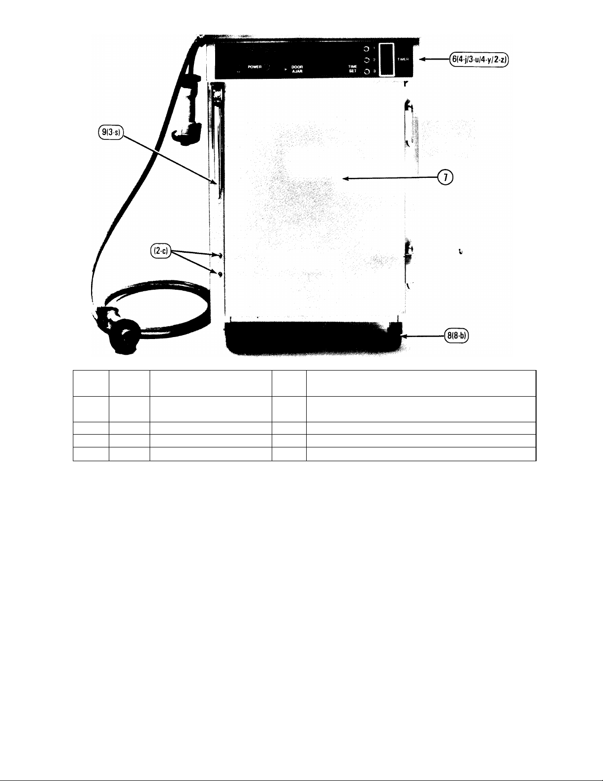
Page 7
ITEM
PART
NO.
6 63426 Rear Control Panel Sub-
7 62370 Rear Door Wrap 1 Provides an exterior cover for the cavity door assembly.
8 63041 Ridged Wheel 2 Allows the unit to be moved about.
9 62389 Rear Door Handle 1 Provides access to the unit and secures the door closed.
DESCRIPTION QTY. FUNCTION
1 Used to mount electrical control components.
Assembly
4
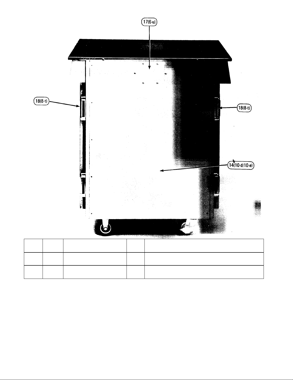
Page 8
ITEM
PART
NO.
17 62376 Blank Electrical Conversion
18 60787 Door Hinge 4 Mounts the doors to the cabinet and allows the doors to open
DESCRIPTION QTY. FUNCTION
1 Opposite side cover for power conversion.
Panel
and close. (2 per front and rear door)
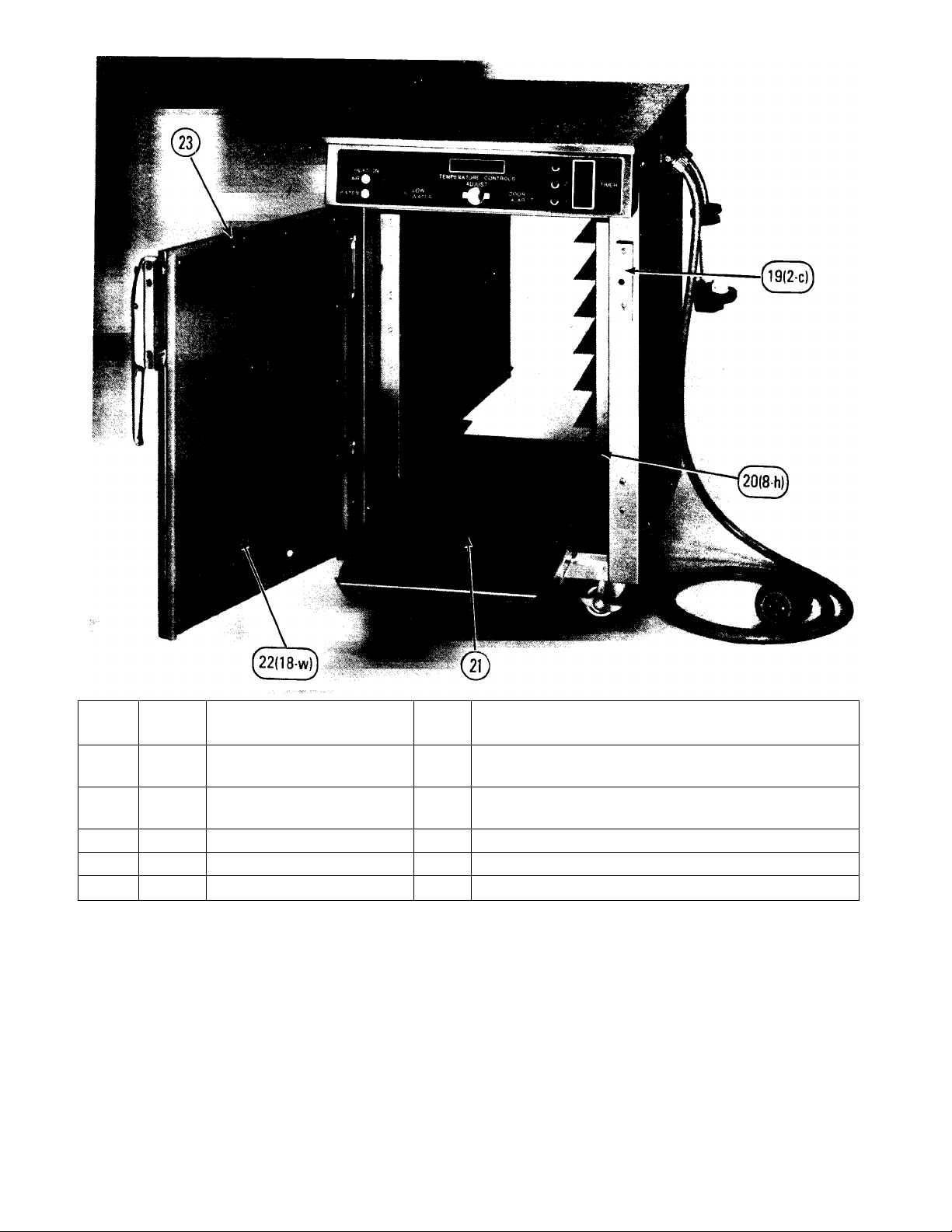
Page 9
ITEM
PART
NO.
19 63045 Front Door Striker Plate 1 Latches door to cabinet and houses the door ajar sensor.
20 63212 Tray Rack 2 Holds biscuit tray. (1 for the left and 1 for the right sides of the
21 60794 Crumb Shield 1 Prevents crumbs from falling into the water.
22 62373 Front Door Interior Panel 1 Secures the door gasket and protects the insulation.
23 60820 Front Door Gasket 1 Seal to retain the interior environment.
DESCRIPTION QTY. FUNCTION
cavity)
7
Page 10
ITEM
PART
NO.
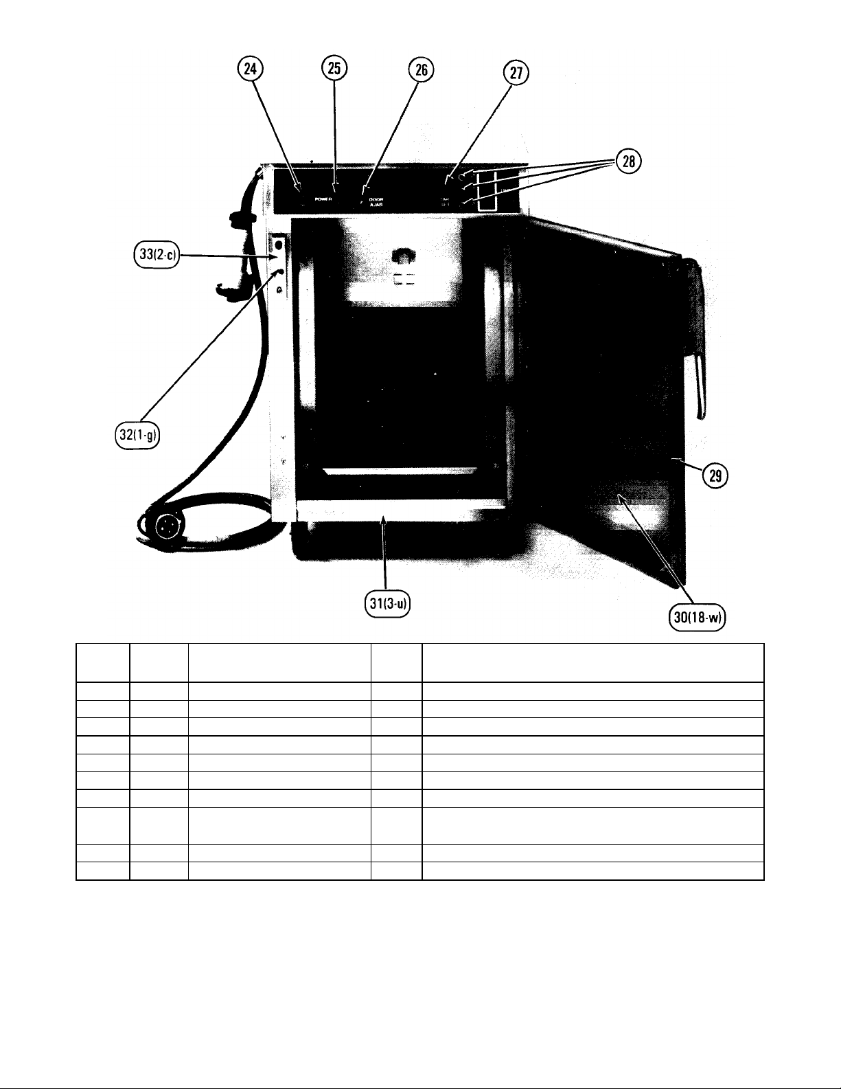
24 61776 Power On Switch 1 Turns the electrical power on or off to the unit.
25 60758 Power Telite (Red) 1 Indicates that the power is on to the unit.
26 60825 Rear Door Ajar Telite (L.E.D.) 1 Indicates when the front door is ajar.
27 62417 Timer Program Switch 1 Programs the desired time into the internal product timer.
28 62418 Timer Operate Switch 3 Starts and stops the internal product timer.
29 62411 Rear Door Gasket 1 Seal to retain the interior environment.
30 63206 Rear Door Interior Panel 1 Secures the door gasket and protects the insulation.
31 62364 Bottom Panel 2
32 62397 Rear Door Ajar Sensor 1 Detects when the rear door is closed or open.
33 62389 Rear Door Striker Plate 1 Latches door to cabinet and houses the door ajar sensor.
DESCRIPTION QTY. FUNCTION
Covers the front and rear lower frame members. (1 in the
front and 1 in the rear of the unit)
8
Page 11
ITEM
*Not shown
PART
NO.
34* 60819 Front Door Insulation
35* 60819 Rear Door Insulation
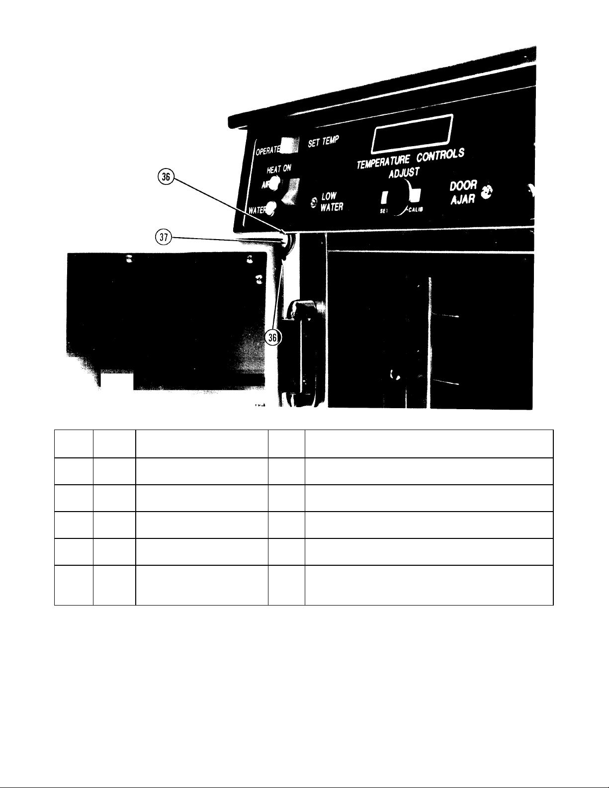
36 62392 Conduit Bushing 4 Guide for the front and rear thermocouple conduit. (2 each
37 62393 Thermocouple Conduit 2 Conduit for the front and rear air thermocouple wires. (1
38* 56315 Thermocouple Conduit
DESCRIPTION QTY. FUNCTION
1 Thermal seal for the front door.
(not shown)
1 Thermal seal for the rear door.
(not shown)
door)
each, front and rear door)
2 Abrasion barrier between the air sensor thermocouple wires
Insulation Tubing (not shown)
and the thermocouple conduit for the front and rear doors. (1
each front and rear door)
Page 12
ITEM
PART
NO.
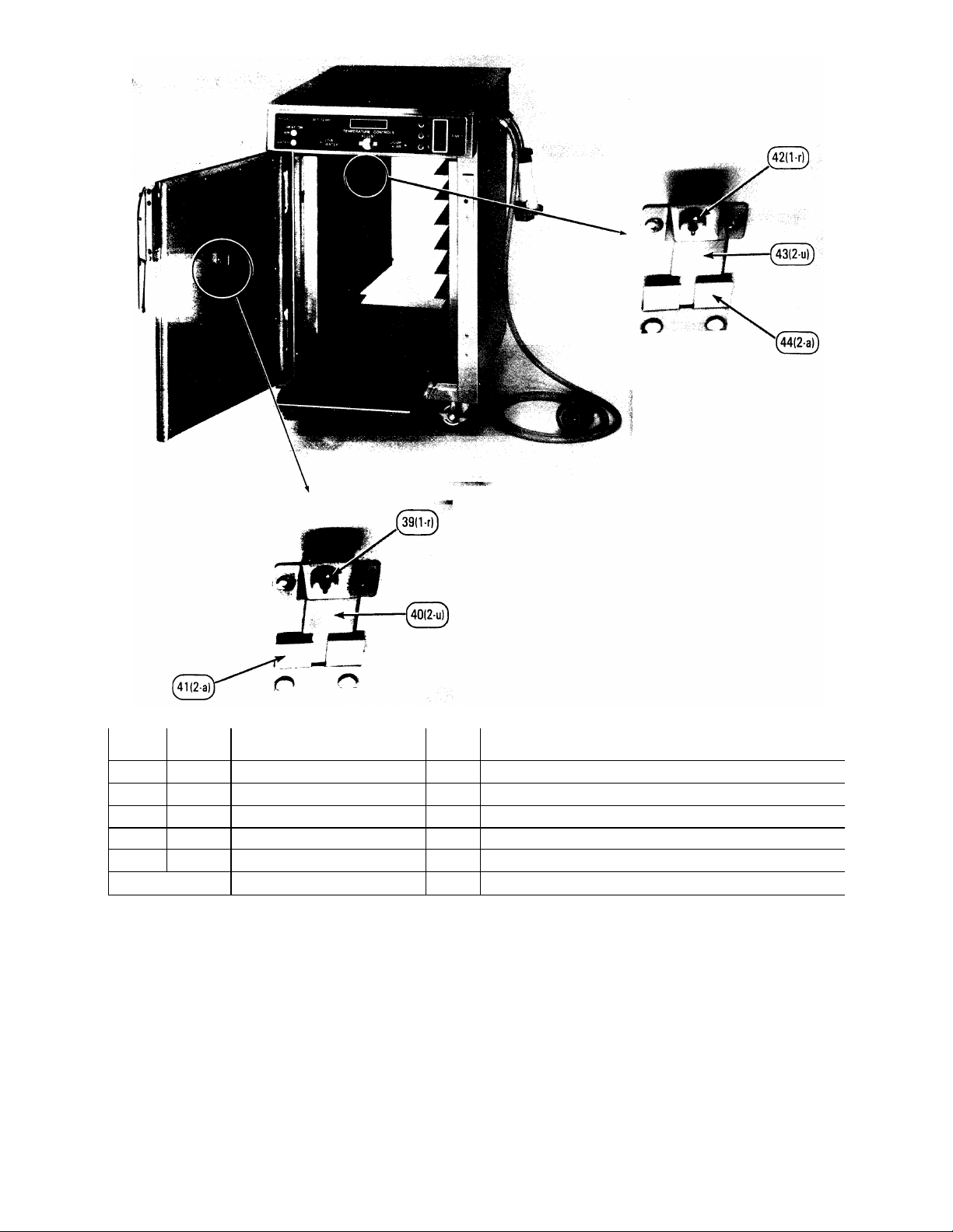
39 62367 Front Door Air Sensor 1 Senses the air temperature inside the unit.
40 60789 Front Thermo Bracket 1 Protective guard for the air sensor.
41 62379 Front Air Probe Bracket 1 To hold biscuit oven probe.
42 62413 Rear Door Air Sensor 1 Senses the air temperature inside the unit.
43 60789 Rear Thermo Bracket 1 Protective guard for the air sensor.
44 62379 Rear Air Probe Bracket 1 To hold biscuit oven probe.
DESCRIPTION QTY. FUNCTION
10
Page 13
ITEM
*Not shown
PART
NO.
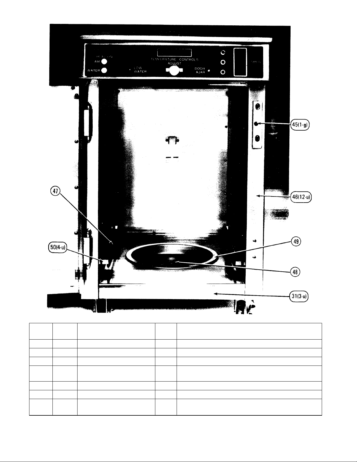
45 62388 Front Door Ajar Sensor 1 Detects when the front door is closed or open.
46 63204 Cavity Assembly 1 Provides the interior surface of the unit.
47 62375 Air Heating Element 2 Heats the air within the cabinet. (1 each side)
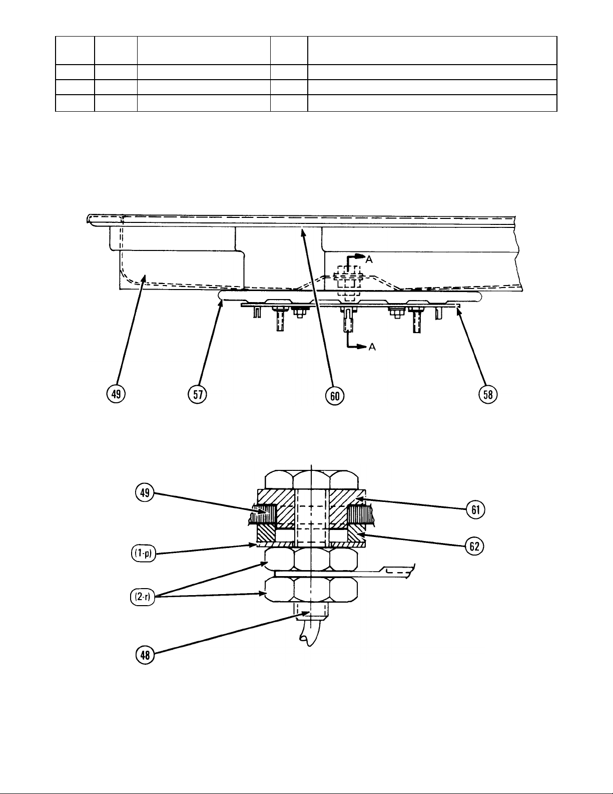
48 60815 Thermal/Low Water Sensor
49 60807 Water Pan 1 Holds water for humidity.
50 60752 Element Clip 4 Holds the element in place. (2 clips per element)
51* 60799 Side Insulation (not shown) 2 Thermal barrier for both sides of the cabinet, 1 piece per for
DESCRIPTION QTY. FUNCTION
1 Senses temperature and water level within the water pan.
Assembly
each side.
11
Page 14
ITEM
PART
NO.
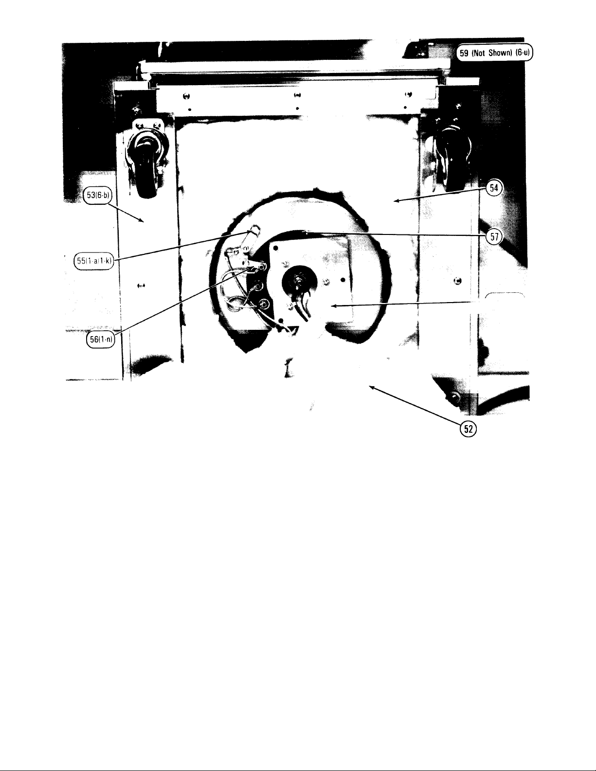
52 60782 Outer Bottom Insulation 1 Thermal seal around the water pan.
53 62368 Base Rail 2 Base for the wheels to attach to. (1 per each side of the unit)
54 60751 Inner Bottom Insulation 1 Thermal seal around the water pan.
55 60527 High-Limit Water Thermostat 1 Safety device which prevents excessive water pan
56 50002 Electrical Jumper 1 Connects the water heating element to the high limit
57 60768 Water Heating Element 1 Heats the water in the pan.
58 60810 Water Heater Element Retainer 1 Holds the water heating element in place.
59* 63044 Base Cover Assembly (not
*Not shown
DESCRIPTION QTY. FUNCTION
temperature.
thermostat.
1 Covers the water heating element and associated wiring.
shown)
12
Page 15
ITEM
PART
NO.
60 61056 Water Pan Gasket 1 Seals the water pan to the bottom of the cavity.
61 61030 Shoulder Washer 1 Water seal and upper sensor insulator.
62 61031 Washer 1 Water seal and lower sensor insulator.
DESCRIPTION QTY. FUNCTION
SIDE VIEW
(BOTTOM OF CABINET)
CROSS SECTION A-A
13
Page 16

ITEM
*Not shown
PART
NO.
63* 62392 Wiring Bushing (not shown) 2 Protects the wiring from the sharp edges of the cavity sides.
64 51040 Insulation Grommet 2 Protects the wiring from the sharp edges of both sides.
65 62360 Frame Assembly 1 Substructure of the entire cabinet.
66 62418 Timer Operate Switch 3 Starts and stops the internal product timer timing.
67 60825 Front Door Ajar Telite (L.E.D.) 1 Indicates when the rear door is open or closed.
68 63203 Hole Plug 1 Covers the temperature set and calibrate controls.
69 60825 Low Water Telite (L.E.D.) 1 Indicates when water is required.
70 60763 Air/Water Mode Rocker Switch 1 Used to select temperature readout on the display to air or
71 60890 Red Rocker Cover for the
72 60563 Thermostat Telite (White) 2 Indicates when a heater is on.
73 60890 Red Rocker Cover for
74 60763 Operate/Set Temp. Mode
DESCRIPTION QTY. FUNCTION
(1 each, left and right side)
water.
1 External cover for the rocker switch and provides means to
Air/Water Switch
Operate/Set Temp. Switch
Rocker Switch
operate switch.
1 External cover for the rocker switch and provides means to
operate switch.
1 Used to select temperature set and operate functions and
changes the display accordingly on the temperature
controller.
14
Page 17

Term. Power SW.
ITEM
PART
NO.
75 62415 PC Board Support 4 Provides the required spacing of the time display board to the
76 63039 Front Time Display PC Board 1 Displays the product hold time.
77 63040 Timer Control PC Board 1 Logic controller for the time display boards.
78 62409 L.E.D. Telite Lens 1 Protects the telite.
79 62410 L.E.D. Telite Base 1 Mounts the L.E.D. telite to the front control panel.
80 63049 Transformer 1 Provides low voltage power to the electronic controls.
81 60310 Power Terminal Block 1 Connection block for the main power supply to the unit.
82A 60305 Temperature Controller with
DESCRIPTION QTY. FUNCTION
front control panel and attaches it to the panel.
1 Solid state controller for the air and water temperature.
Std./Aux. WO/side pots & 12
82B 69064 Temperature Controller with
1 Solid state controller for the air and water temperature.
Wet/Dry SW. W/side pots and 4
83 63201 Spacer 4 Provides the required spacing of the temperature controller
from the front control panel.
15
Page 18

ITEM
PART
NO.
84 62409 L.E.D. Telite Lens 1 Protects the telite.
85 62410 L.E.D. Telite Base 1 Mounts the L.E.D. telite to the front control panel.
86 63201 Spacer 4 Provides proper spacing of the door sensor controller to the
87 62398 Door Sensor Control PC Board 1 Solid state device that determines and indicates whether a
88 60964 Water Relay 1 Turns the water heater on and off.
89 60870 Air Relay 1 Turns the air heaters on and off.
90 62399 Electronic Component Bracket 1 Used to mount electrical control components.
DESCRIPTION QTY. FUNCTION
component bracket.
door is open or closed.
16
Page 19

ITEM
PART
NO.
91 63039 Rear Time Display Board 1 Displays the product hold time.
92 62415 PC Board Support 4 Provides the required spacing of the time display board to the
93 63038 Timer Speaker 1 Produces audible 3-tone sound, indicating the end of a time
94 57260 Speaker Bracket 1 Holds the speaker in place.
95 62409 L.E.D. Telite Lens 2 Protects the telite.
96 62410 L.E.D. Telite Base 2 Mounts the L.E.D. telite to the front control panel.
DESCRIPTION QTY. FUNCTION
rear control panel and attaches it to the panel.
cycle from the internal timer.
17
Page 20

ITEM PART
NO.
97 61102 Thermostat Strap 1 Holds the air high-limit thermostat in place.
98 60824 Top Insulation 1 Thermal seal for the top of the unit.
99 61183 Air High-Limit Thermostat 1 Safety device which prevents excessive internal cabinet
DESCRIPTION QTY. FUNCTION
temperatures.
18
Page 21

HARDWARE IDENTIFICATION
ITEM PART NO. DESCRIPTION TOTAL QUANTITY
a 51053 Nut, Hex 8-32, Kep 25
b 53890 Screw, Pan Hd. Phil. 12-24 x 3/4 22
c 53983 Screw, Rd. Hd. Sltd. 10-32 x 1/2 8
d 54285 Screw, Flt. Hd. Phil. 8-32 x 3/8 20
e 55137 Speednut 8-32 Long 20
f 55736 Nut, Hex 8-32 Green Kep 2
9 58625 Retainer, Circ Push-On 5/16 ID. 2
h 60670 Screw, Trs. Hd. Sltd. 1/4-20 x 3/8 8
j 60680 Nut, Hex 10-32 Kep 8
k 51333 Screw, Rd. Hd. Sltd. 6-32 x 3/8 1
1 52176 Nut, Hex 8-32 w/Stems 3
m 52242 Washer, Brass Lrg. Pat. #10 3
n 57457 Screw, Binding Hd. 10-32 x 3/8 1
p 61035 Washer, Flt. 5/16 SS. 1
r 61036 Nut, Hex 5/16-18 Unc SS. 4
s 60821 Screw, Flt. Hd. 10-32 x 1-1/2 6
t 60822 Screw, Flt. Hd. 10-32 x 1/2 16
u 61620 Screw, Truss Hd. Phil. 8-32 x 1/2 46
v 62067 Screw, Truss Hd. Phil. 10-32 x 3/8 12
w 55487 Screw, Truss Hd. Phil. 8-32 x 5/16 36
y 53961 Nut, Hex 6-32 Kep 14
z 51708 Nut, Hex 8-32 2
aa 62432
Nut. Hex 1/2 NPT DABC-1PS
DABC-1TL
2
1
19
Page 22

EQUIPMENT SET-UP AND CLOSE
PROCEDURES
Set-up — Complete the following:
1. Ensure that the power cord is plugged into the
appropriate power source.
2. Ensure that the water pan has melted ice in it and
is approximately two-thirds full.
3. Turn the power switch to the ON position.
4. Ensure that the temperature setting for both the air
and water (flashing digital display) are set
correctly. (See PMS Card #64)
5. Ensure that both doors are closed (check the
DOOR AJAR lights).
6. Allow the unit to warm up for forty-five (45) minutes
before placing product inside.
7. Ensure that the timers are set for the correct time.
CAUTION: On model DABC-1PS the yellow plug is
for 120V, 15amp auxiliary power to other
appliances, ie. Marinator (Model MDMW-3).
Close — Complete the following:
1. Turn the power switch to the OFF position.
2. Unplug the power cord from the power source and
allow the unit to cool down.
CAUTION: THE EQUIPMENT AND THE WATER
CONTENTS ARE HOT! THE HEATING ELEMENTS WILL
BURN YOU!! ALLOW THE CABINET TO COOL DOWN FOR
APPROXIMATELY 30 MINUTES WITH BOTH DOORS
OPEN.
3. Remove the crumb tray and side racks.
4. Sponge out the remaining water in the water pan.
5. Using a clean, damp cloth, wipe out the water pan and
the interior of the cabinet.
6. Wipe down the exterior of the cabinet.
7. Replace the side racks.
8. Fill the water pan with ice or melted ice.
9. Replace the crumb tray.
PROCEDURE TO ATTACH OVEN
PROBE TO CABINET
1. Open the front door of the biscuit cabinet (the
door associated with the temperature digital
display).
2. Hold the Biscuit Oven Probe with the sloped
angle toward the inner rear door and with the
alligator clip at the bottom on the right side.
3. Move the Biscuit Oven Probe up above the air
probe bracket and move it back near the rear
inner door of the cavity.
4. Move the Biscuit Oven Probe down onto the air
probe bracket so that the narrow section of the
tapered angle (cobraneck) of the Biscuit Oven
Probe fits into the slot in the air probe bracket.
5. Push the Biscuit Oven Probe down onto the air
probe bracket until it stops.
20
Page 23

PROCEDURE FOR CABINET STORAGE
1. Turn the power switch to the OFF position.
2. Unplug the power cord from the power source
and allow the unit to cool down.
CAUTION: THE EQUIPMENT AND THE WATER
CONTENTS ARE HOT! THE HEATING ELEMENTS
WILL BURN YOU!! ALLOW APPROXIMATELY 30
MINUTES WITH BOTH DOORS OPEN FOR THE UNIT
TO COOL DOWN.
3. Remove the crumb tray and the side racks.
4. Sponge out the remaining water in the water
pan.
5. Using a clean, damp cloth, wipe out the water
pan and the interior of the cabinet.
6. Wipe down the exterior of the cabinet.
7. Replace the side racks and the crumb tray.
8. Wrap the power cord and plug around the
cabinet and secure as shown.
9. Move the cabinet to its storage location.
2. Remove the top cover from the cabinet by
removing the four (4) screws.
3. Remove only the four (4) screws from the top and
bottom of the blank conversion panel (Item 17) and
one (1) of the side screws. This will allow the panel
to pivot on the remaining screw to a position where
you can hold onto it with your fingers. Holding the
panel (so that it will not drop down between the
side panel and the side insulation), remove the
remaining side screw and remove the blank
conversion panel from the side of the unit.
4. Remove all six (6) screws from the electrical
conversion panel (the one with the cords attached
— Item 11) and allow the assembly to hang freely.
5. Pass the electrical conversion panel through the
passageway at the top of the cabinet, pulling the
two cords and plugs with it. Be careful not to snag
and pull any of the internal wiring with the electrical
conversion panel or plugs as you pass them
through the unit.
6. Pass the plugs and cords through the left-hand
passageway, pulling the electrical conversion
panel with them.
7. Secure both conversion panels to the cabinet sides
using the six (6) screws previously removed and
#222 loctite.
8. Replace the top cover to the cabinet and secure
with the four (4) screws.
TIMER OPERATION
Introduction
The Dual Access Biscuit Cabinet models have the
product timer as an integral part of the unit. The timer
within the cabinet consists of three independent
product timers that can be activated from the front or
rear control panels with the timer program switch
located on the rear control panel.
Set-Up
1. Make sure that the power cord is plugged into the
appropriate power source.
2. Turn the power switch to the ON position.
3. Verify that the time being displayed is correct; if
not, correct the time using the following
instructions:
To Program Times
1. Wait for the channel selected to time out or cancel
the time manually.
PROCEDURE TO CHANGE CORD FROM RIGHTHAND SIDE TO LEFT-HAND SIDE
1. Unplug the cord from the power source.
21
Page 24

2. Press and hold the PROGRAM switch (Item #27) to
the left to change tens of minutes and to the right to
change minutes.
3. Press the OPERATE switch (Item #28) of the channel
display to be changed. The display will turn to
maximum brightness.
NOTE: Holding the OPERATE switch in will cause the
display to rotate automatically from "0" through "9".
5. After the timer has counted down to zero time, a threetone audible signal will be heard and the timer display
will read "00" and flash. To stop the audible signal,
press the operate switch (Item 28 or 66) adjacent to
the blinking time display. This will stop the audible
signal and return the timer to its original setting and
the display will be dim and constant.
TROUBLESHOOTING
NOTE: Both displays (front and rear control panels) will
read the same.
Operation
1. Make sure that the power cord is plugged into the
appropriate power source.
2. Turn the power switch to the ON position.
3. Verify that the time being displayed is correct. If it is not
correct, set the time as explained in TO PROGRAM
TIMES section.
4. To activate the timer, press the timer operate switch
(Item 28 or 66) next to the corresponding time display
(on either side of the cabinet). The display will
become brighter and a timer indicator dot will appear
in the lower right hand corner.
TROUBLESHOOTING GUIDE
PROBLEM PROBABLE CAUSE CORRECTIVE ACTION
Unit fails to operate. (No
power or telite indications.)
Faulty power switch. Replace power switch. (See page 25.)
Unit fails to operate. (Power
telite is all that works.)
Faulty air high limit thermostat. Replace air high limit thermostat. (See page
Holding temp. too high. Air temp. set too high. Check air temp. setting. (See PMS Card #64.)
Power switch off. No power to unit. Turn power switch on. Verify plug connection,
Air temp. set too high. Check air temp. setting, allow unit to cool
In servicing the equipment which has malfunctioned, it is
very important to:
1. DEFINE the problem and accurately determine
what is the malfunction.
2. Determine the BASIC CAUSE.
3. ELIMINATE the cause and repair the malfunction. If
the cause is not properly identified and eliminated, the
malfunction may recur.
It is usually relatively easy to define the malfunction, but
sometimes very difficult to spot the cause.
If the problem remains after following the suggestions
listed, contact Wells Manufacturing Company Service
Department at (702) 345-0444.
check circuit breaker, check voltage supply to
unit.
down. (See PMS Card #64.)
25.)
Unit out of calibration. Recalibrate the unit. (See PMS Card #64.)
Holding temp. too low. Air temp. set too low. Check air temp. setting. (See PMS Card #64.)
Unit out of calibration. Recalibrate the unit. (See PMS Card #64.)
Door(s) ajar. Close the door(s).
22
Page 25

PROBLEM PROBABLE CAUSE CORRECTIVE ACTION
never
recovers.
Finished product too dry. Air temp. set too high. Check air temp. setting. (See PMS Card #64.)
Water temp. set too low.
Low water level.
Check water temp. setting. (See PMS Card
#64.)
1. Check low water telite; should be on and
sounding. 2. Refill water pan.
Door(s) ajar. Check door ajar telite(s); if on, close door(s).
Door gasket leak. Adjust door. (See page 25.)
Finished product too moist. Air temp. set too low. Check air temp. setting. (See PMS Card #64.)
Water temp. set too high.
Check water temp. setting. (See PMS Card
#64.)
Unit out of calibration. Recalibrate the unit. (See PMS Card #64.)
Air or water temp. is above
set temp. but telite indicates
Defective temp. control board or relay.
power to heaters.
Air or water temp. is below set
temp. but telite does not indicate
power to heaters.
Unit out of calibration. Recalibrate the unit. (See PMS Card #64.)
Defective temp. control board or relay.
Replace temp. control board. (See page 26.)
Replace air relay. (See page 27.)
Replace temp. control board. (See page 26.)
Replace temp. relay. (See page 27.)
Both doors ajar. Close the doors.
Air or water temp. is constantly
below the set temp. and the unit
Defective heating element.
Replace air heater. (See page 27.) Replace
water heater. (See page 28.)
Water over temp. thermostat defective (for
water only).
Replace water over temp. thermostat. (See
page 29.)
Air thermocouple shorted (for air only). Replace air thermocouple. (See page 26.)
Door(s) ajar (for air). Close door(s).
Low water indicator is on but
water tray is full.
Soft or distilled water used. Add a pinch of salt to the water.
Defective temp. control board.
Replace temp. control board. (See page 26.)
Defective low water sensor. Replace water sensor. (See page 29.)
Low water indicator does not
go on when water tray is
empty.
Short circuit from low water sensor to water
tray.
Defective temp. control board.
Repair water sensor. (See page 29.)
Replace temp. control board. (See page 26.)
23
Page 26

PROBLEM PROBABLE CAUSE CORRECTIVE ACTION
Air or water temperature
readout is 0 to 2 degrees
and will not change.
Both doors ajar. Check door ajar telite, should be on, close
Defective door control board. Replace door control board. (See page 30.)
Air or water temperature
readout is at room temp. and
will not change.
Door ajar telite will not turn
Defective door sensor. Replace door sensor. (See page 31.)
Door control board requires adjustment or is
Time display readout does
not work correctly.
Loose connection. Check wire connections.
Time program cannot be
changed.
Defective time control board. Replace time control board. (See page 33.)
Poor connection of thermocouple wires to
control boards or defective thermocouple.
Thermocouple shorted or defective. Check Thermocouples Air: (See page 26.)
Door not closed. Check doors and close.
defective.
Defective display or control board. Replace the display or control board. (Display
Defective program switch. Replace program switch. (See page 33.)
Check thermocouples Air: (See page 26.)
Water: (See page 29.)
door.
Water: (See page 29.)
Adjust controller or replace door control board.
(See page 30.)
see page 33.) (Control see page 33.)
Loose connection. Check wire connections.
Timer does not start when
activate switch is pushed.
Defective activate switch. Replace operate switch. (See page 34.)
Loose connection. Check wire connections.
Defective time control board. Replace time control board. (See page 33.)
PARTS ORDERING/SERVICE INFORMATION
If service parts or technical information is required, please
contact the Factory Service Department. To help speed up
your inquiry the following information is required.
1. Model Number:_______________________
2. Serial Number: __________________________ (fill in
for your records.)
3. Voltage: ________________________________
4. Item Part Number: ____________________
5. Quantity Required: _____________________
6. Nature of Service problem and symptoms.
7. Any other information that may be helpful in solving your
service problem.
NON-SCHEDULED MAINTENANCE
Under normal conditions, with proper use and cleaning,
very little non-scheduled maintenance (NSM) will be
required for this unit. However, this
section provides procedures for checking and
replacement of various parts and components used
within the Dual Access Biscuit Cabinet in the event that it
becomes necessary. Before replacement of any parts,
refer to the Troubleshooting Guide for assistance in
determining the cause of any malfunction and remember,
if in doubt, call the Service Department: Wells
Manufacturing Company, P.O. Box 280, Verdi, Nevada
89439, (702) 345-0444.
WARNING: SOME OF THE PROCEDURES
CONTAINED IN THIS SECTION INVOLVE ACCESSING
BARE ELECTRICAL TERMINALS AND EXPOSURE TO
VOLTAGES CAPABLE OF PRODUCING A FATAL
SHOCK; THEREFORE, THEY MUST BE USED BY
PROPERLY TRAINED PERSONNEL AND STANDARD
SAFETY RULES FOR ELECTRICAL EQUIPMENT
MUST BE ADHERED TO.
Note: Loctite #222 should be applied to all threaded
hardware parts before reassembly (except electrical wire
connection terminals).
24
Page 27

Note: The wiring diagram is located on the
underside of the top of the cabinet. In order to
use it, the top must be removed but only after
the unit has been unplugged from the
overhead electrical power.
Procedure: Replacement of the Power
Switch
Tools: Needle Nose Pliers, Phillips Head
Screwdriver
Parts: Power ON Switch (Item 24)
1. Unplug the cabinet from the power source.
2. Remove the top from the cabinet.
3. Remove the wires from the switch using needle
nose pliers.
4. Push the power switch through the control panel
by depressing the securing clips on the back
side of the switch body.
5. Follow the reverse procedure and the wiring
diagram to install the new power switch.
Procedure: Replacement of the Air High-Limit (OT)
Thermostat
Tools: 11/32 Nutdriver, Phillips Head Screwdriver, 5/16
Nutdriver
Parts: Air High-Limit Thermostat (Item 99)
1. Unplug the cabinet from the power source.
2. Remove the top from the cabinet and move the
insulation covering the thermostat located in the
center of the cavity top.
3. Disconnect the two wires from the thermostat.
4. Remove the two hex nuts from the thermostat
strap (Item 97) that holds the thermostat in
place and remove the strap.
5. Remove the thermostat and replace it with the new
Air High-Limit Thermostat.
25
6. Follow the reverse procedure to install the
new thermostat.
CAUTION: MAKE SURE THAT THE INSULATION
HAS BEEN REDRESSED ON THE TOP OF THE
UNIT. FAILURE TO DO SO MAY CAUSE OVERHEATING AND SUBSEQUENT FAILURE OF THE
ELECTRONICS WITHIN THE UNIT.
Procedure: Adjustment of the Door
Tools: Phillips Head Screwdriver, 1/8 Slotted
Head Screwdriver
Parts: None
1. ADJUSTMENT OF THE HANDLE SIDE
OF THE DOOR: Loosen the three (3)
screws that hold the door handle in
position.
2. If the door seal is not tight enough, move
the handle away from the striker plate
one notch at a time, tighten the three (3)
screws and check for a tight seal.
Continue until a tight seal is obtained
along the door gasket.
3. If the door seal is too tight, move the
handle towards the striker plate one
notch at a time, tighten the three (3)
screws and check for a tight seal.
Continue until a tight seal is obtained
along the door gasket.
4. Check the seal on the hinge side of the
door after adjustment is complete for
possible need of adjustment.
5. ADJUSTMENT OF THE HINGE SIDE OF THE
DOOR: Pry off the decorative covers on both
the top and bottom hinges.
6. If the door seal is not tight enough, loosen
the four (4) screws that hold the door to
the hinge and move the door towards the
cavity one notch at a time; tighten the
four (4) screws and check for a tight seal;
continue until a tight seal is obtained.
7. If the door seal is too tight, loosen the four (4)
screws that hold the door to the hinges and
move the door away from the cavity one notch
at a time; tighten the four (4) screws
Page 28

and check for a tight seal; continue until a tight seal
Procedure: Inspection/Replacement of the Air
26
is obtained.
8. Check the seal on the handle side of the door
after the adjustment is complete for possible
need of adjustment.
STEP 1
CAUTION: MAKE SURE THAT THE CORK INSULATOR
IS STILL IN PLACE AFTER NEW CONTROL BOARD IS
INSTALLED. FAILURE TO DO SO MAY RESULT IN
CONTROL BOARD FAILURE.
5. Follow the reverse procedure and the wiring
diagram to install the new Temperature Control
Board. Make sure that a spacer is on each of
the four (4) corners and that the retaining wire
for the hole plug (Item 68) is secure on the stud.
STEP 5
Procedure: Replacement of the Temperature
Control Board
Tools: Phillips Head Screwdriver, 1/16 Slotted Head
Screwdriver, 11/32 Open or Box-end Wrench,
Needle Nose Pliers
Parts: Temperature Control Printed Circuit
Board (Item 82)
1. Unplug the cabinet from the power source.
2. Remove the top from the cabinet.
3. Remove the wires from the control board using
needle nose pliers.
Note: Do not remove the wires connected to the
ORANGE TERMINAL BLOCK. To remove their
connection from the PC Board, just lightly pull the
ORANGE TERMINAL block from the PC Board.
4. Remove the four (4) mounting nuts located in the
corners of the control board and remove the control
board from the mounting studs.
CAUTION: DO NOT LOSE THE SPACERS THAT
POSITION THE CONTROL BOARD TO THE FRONT
PANEL BECAUSE THEY MUST BE REUSED.
Sensor Thermocouple
Tools: Phillips Head Screwdriver, 1/8 Slotted Head
Screwdriver, 1/2-inch Open or Box-end Wrench
(2 required)
Parts: Air Temperature Sensor, Thermocouple (Item
39 for front door; Item 42 for rear door)
1. Unplug the cabinet from the power source.
2. Remove the top from the cabinet.
3. FOR INSPECTION OF WIRES ONLY: Check
the connections of the thermocouple wires from
the Air Temperature Sensors to the Door
Sensor Control Board and the same
connections to the Temperature Control Board
(yellow and red wires from the Door Sensor
Control Board to the Temperature Control
Board).
Note: It may be necessary to remove the wires and
reinstall them in order to verify whether they are
secure.
Page 29

4. FOR REPLACEMENT OF WIRES ONLY:
Disconnect the corresponding thermocouple
wires from the Door Sensor Control Board.
5. Open the corresponding door and remove the
thermoguard from the interior of the door.
6. Remove the inner door panel and gasket from the
door.
7. Hold the air temperature sensor on the front of the
inner door panel with a 1/2-inch wrench and remove
the nut from the rear of the inner door panel with the
second 1 /2-inch wrench.
8. Pull the air temperature sensor and thermocouple
wire through the conduit and door panel to remove
it.
2. Remove the top from the cabinet.
3. Disconnect the wiring from the relay using needle
nose pliers.
4. Remove the nut from the mounting stud and
remove the relay.
Note: Pay attention to the position of the relay
terminals with respect to the front and rear of the
cabinet. The new relay must be installed in the same
orientation or the wire lengths will not be correct for
reconnection to the new relay.
5. Place a small amount of silicone heat transfer
agent (white paste) onto the bottom (metal plate)
of the new relay and install it over the stud in the
same orientation as the one removed (use this
procedure picture for the correct relay orientation).
6. Follow the reverse procedure and the wiring
diagram to install the new relay.
CAUTION: DO NOT LOSE THE INSULATION TUBING
PROTECTING THE UPPER END OF THE CONDUIT
BECAUSE IT MUST BE REUSED.
9. Follow the reverse procedure and the wiring diagram
to install the new Air Temperature Sensor.
Note: Loctite #222 must be reused on all threaded
hardware in the reassembly of the inner door panel.
Procedure: Replacement of the Air or Water Relays
Tools: Phillips Head Screwdriver, 11/32 Nut-driver,
Needle Nose Pliers
Parts: Water Relay and/or Air Relay (Item 88 for
Water; Item 89 for Air)
1. Unplug the cabinet from the power source.
Procedure: Replacement of the Air Heating Element
Tools: Phillips Head Screwdriver, 1/8 Slotted
Head Screwdriver, Pliers
Parts: Air Heating Element (Item 47)
1. Unplug the cabinet from the power source.
2. Open both doors and remove the rack assemblies
and crumb tray from the interior of the unit.
3. Remove the corresponding outer side panel.
4. Remove the side insulation and remove the wires
from the element terminals. Use pliers to hold the
terminal so that it will not turn.
27
Page 30

5. Remove the element clips from the interior of the
cabinet, remove the element from the cabinet
and remove the clips from the element by
sliding them around the element sheath and
over the terminal ends.
6. Follow the reverse order to install the new element.
CAUTION: MAKE SURE THAT THE INSULATION IS
REINSTALLED INTO THE SIDE OF THE UNIT FOR
PROPER UNIT OPERATION.
5. Remove the water temperature thermocouple and
the low water sensor wires from the Temperature
Control Board using needle nose pliers and the flat
head screwdriver. Pull the wires through the two
openings in the cavity side to free them from the
unit.
6. Remove the three nuts from the wire terminals of
the heating element and remove the wires.
7. Remove the three nuts from the element retaining plate
and remove the element.
8. Follow the reverse procedure and the wiring
diagram to install the new Water Heating Element.
Procedure: Replacement of the Water Heating
Element
Tools: Phillips Head Screwdriver, 11/32 and 5/16
Nutdrivers, Needle Nose Pliers, 1/8 Slotted
Head Screwdriver
Parts: Water Heating Element (Item 57)
1. Unplug the cabinet from the power source.
2. Remove the excess water, racks, and crumb tray
from the unit.
3. Remove the top of the unit and gently lay the unit
on its left side.
4. Remove the right side panel, bottom cover, side
insulation and the bottom outer insulation from the
unit.
CAUTION: MAKE SURE THAT THE WATER
TEMPERATURE THERMOCOUPLE AND THE LOW
WATER SENSOR WIRES ARE ROUTED THROUGH THE
INSULATION SUCH THAT THE INSULATION LIES
BETWEEN THE WIRES AND THE WATER HEATING
ELEMENT. ALSO MAKE SURE THAT THE SIDE
INSULATION IS REINSTALLED FOR PROPER UNIT
OPERATION.
28
Page 31

Procedure: Replacement of Water High-Limit
4. FOR REPAIR ONLY:
Thermostat
Tools: 11/32 Nutdriver, Phillips Head Screwdriver, 1/8
Slotted Head Screwdriver
Parts: High-Limit Water Thermostat (Item 55)
1. Unplug the cabinet from the power source.
2. Remove the excess water, the racks and the crumb
tray from the unit and gently lay it on its side.
3. Remove the bottom cover from the cabinet and the
outer bottom insulation.
4. Remove the wire from the thermostat and
disconnect the thermostat arm from the brass
jumper.
5. Remove the nut holding the thermostat in place
and remove the thermostat.
6. Follow the reverse procedure to install the new
Water High-Limit Thermostat.
CAUTION: MAKE SURE THAT THE WATER
TEMPERATURE THERMOCOUPLE AND THE LOW
WATER SENSOR WIRES ARE ROUTED THROUGH THE
Procedure: Inspection/Repair/Replacement of the
Thermal/Low Water Sensor
Tools: Phillips Head Screwdriver, 1/8 Slotted Head
Screwdriver, 1/2-inch Open or Box-end Wrench
(2 required). Needle Nose Pliers
Parts: Thermal/Low Water Assembly (Item 48), Teflon
Washer/Spacer Set (Items 61 and 62)
1. Unplug the cabinet from the power source.
2. Remove the top from the cabinet.
3. FOR INSPECTION OF WIRES ONLY: Check the
connections of the thermocouple wires from the
Water Temperature Sensor to the Temperature
Control Board.
Note: It may be necessary to remove the wires and
reinstall them in order to verify whether they are
secure.
INSULATION SUCH THAT THE INSULATION LIES
BETWEEN THE WIRES AND THE WATER HEATING
ELEMENT FOR PROPER UNIT OPERATION.
Gently lay the cabinet on its left side and remove the
side panel, bottom cover, side insulation and the
bottom outer insulation from the unit.
5. Remove the water temperature thermocouple wires
from the Temperature Control Board, using the flat
head screwdriver. Pull the wires through the two
openings in the cavity side to free them from the
unit.
29
Page 32

6. Hold the Sensor Assembly from the inside of the
water pan with a 1/2-inch wrench and remove the
nut from the bottom with the other 1/2-inch wrench.
Parts: Door Sensor Control Board (Item 87)
1. Unplug the cabinet from the power source.
2. Remove the top from the cabinet.
3. REPLACEMENT ONLY:
Disconnect the wires from the Door Sensor Control
Board using needle nose pliers and the slotted head
screwdriver.
4. Remove the four (4) nuts holding the control
board in place and remove it from the unit.
CAUTION: DO NOT LOSE THE SPACERS THAT
POSITION THE CONTROL BOARD TO THE
MOUNTING BRACKET BECAUSE THEY MUST BE
REUSED.
7. Pull the Sensor Assembly through the water-pan
and remove it from the unit.
8. Replace the two-piece teflon washer/spacer
assembly (Items 61 & 62) on the Sensor Assembly
and follow the reverse procedure and the wiring
diagram to install the Sensor Assembly.
9. FOR REPLACEMENT ONLY: Replace the two-piece
teflon washer/spacer assembly (Items 61 & 62) and the
Thermal/Low Water Assembly (Item 48) and follow the
reverse procedure and the wiring diagram to install the
new Sensor Assembly.
CAUTION: MAKE SURE THAT THE WATER
TEMPERATURE THERMOCOUPLE AND THE LOW
WATER SENSOR WIRES ARE ROUTED THROUGH THE
INSULATION SUCH THAT THE INSULATION LIES
BETWEEN THE WIRES AND THE WATER HEATING
ELEMENT. ALSO MAKE SURE THAT THE SIDE
INSULATION HAS BEEN INSTALLED FOR PROPER UNIT
OPERATION.
Procedure: Replacement/Adjustment of the Door Sensor
Control Board
Tools: Phillips Head Screwdriver, 11/32 Nut-driver, 1/8
Slotted Head Screwdriver, Needle Nose Pliers,
Multimeter or Voltmeter with 200 millivolt DC range
and alligator clip leads
5. Follow the reverse procedure and the wiring
diagram to install the new Door Sensor Control
Board.
Note: The following adjustment procedure must be
performed each time the Door Sensor Control
Board or the individual door sensor(s) are replaced.
Please reference the diagram below for the
following procedures.
6. ADJUSTMENT PROCEDURE: Connect the
voltmeter to the control board in areas noted as
Front Door Sensor adjustment (see diagram).
Note polarity.
CAUTION: THE FOLLOWING STEPS ARE
PERFORMED WITH THE POWER CONNECTED TO
THE CABINET. USE APPROPRIATE SAFETY.
30
Page 33

7. Set the voltmeter to the 200mv range, plug the cabinet
into the power source and turn it ON.
8. FULLY OPEN the FRONT door and note the
reading of the voltmeter. Adjust PI so that the
voltmeter reads between +70 and +80 millivolts.
9. Close and open the door. Verify that the door ajar
telite is working and that the reading of the
voltmeter is a NEGATIVE voltage when the door
is closed.
10. Repeat steps 6 through 9 for the REAR DOOR
except connect the voltmeter to the control
board in areas noted as Rear Door Sensor
adjustment and adjust P2 instead of PI (see
diagram).
11. After adjustments have been made, reinstall the
top of the cabinet.
Procedure: Adjustment/Replacement of the Door Ajar
Sensor
Tools: Phillips Head Screwdriver, 1/2-inch Box-end
Wrench
Parts: 5/16 Retainer (Item g). Door Sensor (Item 32, Rear
Door; Item 45, Front Door), Clear RTV
1. Unplug the cabinet from the power source.
2. Remove the top from the cabinet.
3. Remove the RIGHT side of the cabinet and remove the
side insulation.
4. Remove the corresponding door Striker Plate from the
unit.
31
Page 34

5. Disconnect the sensor wires from the Door Sensor
Control Board and remove the sensor by pulling it
through the cabinet and frame (see diagram below).
6. Using the 1/2-inch box-end wrench, press the 5/16
retainer (Item g) onto the small tube end of the
sensor (Item 32 or 45) so that it is approximately 1
/4-inch past the end of the sensor.
7. Insert the wires through the cabinet and frame
and place the sensor in position.
8. Reinstall the door Striker Plate and verify that the
sensor is recessed a maximum of 1 /32-inch to flush
with the door striker plate. If not, adjust the sensor
position by moving the 5/16 retainer.
9. Seal the sensor end with the clear RTV.
10. Follow the reverse procedure to finish installing the
door sensor.
CAUTION: MAKE SURE THAT THE SIDE INSULATION
HAS BEEN REINSTALLED FOR PROPER UNIT
OPERATION.
11. ADJUSTMENT ONLY:
The Door Sensor Control Board must be adjusted to
the new door sensor whenever they are replaced.
Refer to Replacement/Adjustment of the Door
Sensor Control Board (page 30), steps 6 through 10
for the adjustment procedure.
32
Page 35

Procedure: Replacement of the Timer Display
Board
' Tools: Phillips Head Screwdriver, Needle Nose
Pliers
Parts: Time Display Board (Item 76, Front Display;
Item 91, Rear Display)
3. Disconnect the wires from the Timer Control Board using
the needle nose pliers.
CAUTION: DO NOT USE PLIERS TO REMOVE THE
RIBBON WIRES FROM THE CONTROL BOARD. TO
REMOVE, GENTLY PULL UP ON THE HOUSING USING
YOUR FINGERS.
1. Unplug the cabinet from the power source.
2. Remove the top from the cabinet.
3. Disconnect the activate and program switches
(as applicable) from the Time Display Board
and the ribbon wire from the timer control
board.
4. Using the needle nose pliers, squeeze the tips
of the board retainers and pull the board from
the retainers.
5. Push the new Time Display Board onto the
board retainers until they "pop" into position.
Reconnect the switches per the wiring
diagram.
6. Follow the reverse procedure to finish installing
the new Timer Display Board.
Procedure: Replacement of the Timer Control
Board
Tools: Phillips Head Screwdriver, 5/16 Nutdriver,
Needle Nose Pliers
Parts: Timer Control Board (Item 77)
4. Remove the four (4) nuts holding the control board
in place. Remove the control board from the unit.
5. Install the new Timer Control Board and verify that
the mode jumper is set for a 2x3 timer. If not,
remove the jumper and reconnect it in the 2x3
timer position.
6. Follow the reverse procedure and the wiring
diagram to install the new Timer Control Board.
Procedure: Replacement of the Timer
Program Switch
1. Unplug the cabinet from the power source.
2. Remove the top from the cabinet.
Tools: Phillips Head Screwdriver, Needle Nose
Pliers
Parts: Timer Program Switch (Item 27)
1. Unplug the cabinet from the power source.
2. Remove the top from the cabinet.
3. Disconnect the switch wires from the Time Display
Board.
4. Push the switch from the rear control panel and remove
it from the unit using needle nose pliers, if required.
5. Follow the reverse procedure to install the new
Timer Program Switch.
33
Page 36

Note: Install the new switch with the red wire closest to
the time display board for proper switch operation.
Procedure: Replacement of a Telite (Red or White)
Tools: Phillips Head Screwdriver, Needle Nose
Pliers
Parts: Telite Red (Item 25) or White (Item 72)
1. Unplug the cabinet from the power source.
2. Remove the top from the cabinet.
3. Remove the wires from the rear of the telite
using the needle nose pliers.
4. Using the needle nose pliers, squeeze the two ears
on the plastic body of the telite and push it out of the
control panel.
5. Follow the reverse procedure to install the new
Telite.
Procedure: Replacement of the Timer Operate
Switch
Tools: Phillips Head Screwdriver, Needle Nose
Pliers
Parts: Timer Activate Switch (Item 66, Front Control; Item 28,
Rear Control)
1. Unplug the cabinet from the power source.
2. Remove the top from the cabinet.
3. Disconnect the wires from the time display board.
4. Using the needle nose pliers, remove the nut from
the back of the switch and remove the switch.
5. Follow the reverse procedure to install the new Timer
Activate Switch.
Procedure: Replacement of the Mode Rocker
Switches
Tools: Phillips Head Screwdriver, Needle Nose
Pliers
Parts: Rocker Switch (Item 70 or Item 74), Rocker
Cover (Item 71 or 73)
1. Unplug the cabinet from the power source.
2. Remove the top from the cabinet.
3. Remove the wires from the switch using needle
nose pliers.
4. Push the rocker switch through the control panel by
depressing the securing clips on the back side of the
switch body.
5. Follow the reverse procedure and the wiring
diagram to install the new rocker switch.
34
Page 37

When installed, gently press the rocker cover into
the front of the switch until it snaps into place.
Procedure: Replacement of Door Ajar/Low Water
Telite(s), all or any part
Tools: Phillips Head Screwdriver, Slotted Head
Screwdriver
Note: If the telite does not work after installation,
reverse the LED electrical connection to the LED
light.
Procedure: Replacement of Low Voltage Power
Transformer
Tools: Phillips Head Screwdriver, Needle Nose
Pliers, 11/32 Nutdriver
Parts: Transformer (Item 80)
1. Unplug the cabinet from the power source.
2. Remove the top from the cabinet.
3. Disconnect the wires from the transformer using
needle nose pliers.
4. Remove the two (2) hex nuts securing the
transformer to the component bracket and remove
the transformer.
5. Follow the reverse procedure to install the new low
voltage power transformer.
Parts: LED Light (Item 26 or 67 or 69) and/or Yellow
Lens (Item 78 or 84 or 95) and/or LED Base
(Item 79, 85, 96)
1. Unplug the cabinet from the power source.
2. Remove the top from the cabinet.
3. Remove the LED lens by gently prying it off from
the front of the control panel using the slotted head
screwdriver.
4. Disconnect the LED connector from the LED and
remove the LED base and light from the unit.
5. Replace the appropriate part and follow the reverse
procedure and the wiring diagram to install the
telite.
Note: If the telite does not work after installation,
reverse the LED electrical connection to the LED light.
35
Page 38

Page 39

Page 40

MODEL DABC-1PS 208V, 3
PHASE-Y, 5 WIRE REVISION C
Page 41

Page 42

ADDENDUM TO
EQUIPMENT MANUAL
#43215
The current version of the Dual Access Biscuit Cabinet has externally adjustable control knobs for air and water
temperature as well as a "dry' operation switch. Front and rear "Door Ajar" lights and sensors are no longer provided
on the cabinets
ITEM PART NO. DESCRIPTION QTY FUNCTION
2 60786 Door handle with Striker Plate 1 Provides access to unit and secures front and rear door
when closed
3 68453 Front door wrap 1 Provides an exterior cover for cabinet door assembly
5 69161 Front control panel sub-assembly 1 Used to mount electrical control components
6 69160 Rear control panel sub-assembly 1 Used to mount electrical control components
7 68134 Rear door wrap 1 Provides an exterior cover for cabinet door assembly
9 60786 Door handle with striker plate 1 Provides access to unit and secures front and rear door
when closed
17 69151 Temperature adjustment panel 1 Used to mount water and air temperature
potentiometers and wet/dry switch
17A 60763 Wet/Dry switch 1 Used lo set interior of cabinet for wet or dry operation
17B 69142 Temperature adjustment knob 2 Used to adjust air and water temperature potentiometers
19 60786 Striker plate with door handle 1 Latches Magnetic handle and secures door when closed
20 65073 Tray rack assembly 2 Supports up to 8 biscuit trays in cabinet cavity
22 68402 Front door interior panel 1 Secures door gasket and protects insulation
26 — Deleted — —
32 — Deleted — —
33 60786 Striker plate with door handle 1 Latches magnetic handle and secures door when closed
39.40.41 — Deleted — —
42 68394 Rear door air sensor 1 Senses air temperature inside cabinet
45 — Deleted — —
46 68412 Cavity assembly 1 Provides intenor surface of cabinet
48 66945 Thermal/low water sensor 1 Senses water temperature and level in water pan
53 65181 Base 1 Base for wheels to attach to
55 65478 High limit water thermostat 1 Safely device which prevents excessive water pan
temperature
59 65188 Base cover extension 1 Covers water heating element and associated wiring
61 65476 Shoulder washer 1 Water seal and upper insulator for sensor
62 65475 Washer 1 Water seal and lower insulator for sensor
65 68400 Frame assembly 1 Substructure of the entire cabinet
67 — Deleted — —
80 63049 Transformer 1 Provides low voltage power to electronic controls
82 69064 Temperature controller 1 Solid state controller for the air and water temperature
87 — Deleted — —
90 68411 Electronic component bracket 1 Used to mount electrical control components
95.96 — Deleted — —
1996
WELLS MANUFACTURING COMPANY
Page 43

OPERATING INSTRUCTIONS
for DABC-1 with AUXILIARY OPERATION CONVERSION-140
Standard Operation:
1. Ensure that the power cord is plugged in.
2. Ensure that the water pan is filled approximately
2/3rds full with ice or melted ice.
3. Push the power switch to the "STD" position (top).
4. Verify the air and water temperature settings.
5. Allow the unit to warm up for 45 minutes before
placing product inside.
USE THE STANDARD PMS CARD »#64 FOR CALIBRATION AND TEMPERATURE SET INSTRUCTIONS.
Auxiliary Operation;
1. Ensure that the power cord is plugged in.
2. Ensure that the water pan in EMPTY.
3. Push the power switch to the "AUX" position (bottom).
4. Verify that the air temperature setting is at 140° +/- 5°F. (this cannot be adjusted from
the front panel controls. If it is not correct, refer to the DABC-I Auxiliary Operation
Temperature Setting Instructions).
5. Allow the unit to warm up for I hour before placing product inside (or 15 minutes if you
are changing from the "STD" to the "AUX" mode).
NOTE: The auxiliary power switch position turns off the water heater and low water
indicator, plus it also automatically sets the air temperature to 140° +/- 5°F.
Auxiliary Temperature Setting:
CAUTION; THE FOLLOWING PROCEDURE IS PERFORMED WITH POWER
TO THE UNIT AND EXPOSED ELECTRICAL WIRING.
1. Remove the top from the cabinet and push the power
switch to the "AUX" position (bottom).
2. Place the operation switch on the front control panel to the "SET" position (display is
blinking when the switch is in the set position) and the mode switch to the "AIR"
position.
EPC06/29/892001-0I45263 P/N 45263 Rev. C
Page 44

DABC-I Instructions-14O page 42
3. Locate and adjust the pot that is mounted on a separate printed circuit board and secured
to the temperature control board behind the front control panel. This pot adjusts the
"AUX" air temperature only.
4. Calibration of the cabinet is accomplished in the "STD" power switch setting only. Refer
to PMS card #64 for instructions. (The "AUX" temperature is calibrated at the same time
as the "STD" temperature.)
5. Turn the power off and replace the top of the unit.
P/N 45263 Rev. C
Page 45

DUAL ACCESS BISCUIT CABINET
MODELS DABC-1PSP and DABC-1TL with adiustable controls
TO ADJUST TEMPERATURE:
1. Select SET TEMP on Operate / Set Temp Switch on the front panel.
2. Select AIR or WATER on the Air / Water Switch on the front panel to display AIR or WATER set temperature. Display
will blink.
3. Rotate AIR TEMP. ADJUST, or WATER TEMP. ADJUST knob on side of cabinet CLOCKWISE to INCREASE or
COUNTERCLOCKWISE to DECREASE air or water temperature setting.
4. Select WET on the Wet / Dry Switch on the side of the cabinet if a WATER SET TEMPERATURE is required ( Make sure
that the water pan has been filled with water. ).
5. Select DRY on the Wet / Dry Switch on the side of the cabinet if a WATER SET TEMPERATURE is NOT required ( Moke
sure that the water pan has been emptied. >. The LOW WATER ALARM and WATER HEAT will be disabled and will not
turn on.
1991 WELLS MANUFACTURING CO. INC.
PRINTED IN U.S.A
Item No 4922
REV (-)
Page 46

DABC-I PASTA CONVERSION INSTRUCTIONS
NOTE: If the power switch has an "Aux" position, omit Steps 2 - 6
1. Disconnect power supply cord (plug) from power receptacle, remove
top cover by removing the 4 screws that secure the top to the cabinet and
lift off top cover.
2. Remove original red On/Off rocker type double pole power switch from the rear
control panel by squeezing the 4 plastic retaining fingers at the top and bottom of
the switch housing and applying pressure to the rear of the switch. Disconnect all
the wires from the 4 push-on terminals.
3. Install a new "Aux/Std" combination trim plate and mounting bracket by inserting
through window in rear control panel* (The new <» pole rocker power switch mounts
on the rear of this bracket.)
4. Unplug the piggy-back terminals on pin <4 of the water relay. (Leave wires 26
and 34 connected together.) Tape the junction of these two wires with electrical
tape to prevent the terminals from short ing to other terminals or metal objects.
(See the wiring diagram supplied with the kit.)
5. Reconnect original cabinet wiring per the new wiring diagram (supplied with kit)
and connect new wiring leads to new power switch per wiring diagram. Connect new
wires 69 through 72 and connect the 5 in-line splice connectors supplied with the
kit to the other end of these <4 wires, and one end of wire 73. Connect the other
end of wire 73 to pin <» of the water relay. Install jumpers 7<» and 75 and wires
65 and 66 to the switch.
NOTES Make sure all push-on terminals are tight. If you can remove any of these
terminals by pulling on the wires, they are not tight enough and you will have to
pre-load the female terminal (with the connector unplugged) by lightly squeezing the
rolled edges of the connector terminal with long nose pliers to ensure a tight
connection between the male and female terminals.
6. Assemble the new <» pole power switch to the mounting plate installed in Step 3
by snapping the 4 metal tabs into the 4 front rectangular holes in the bracket.
EPC05/13/91@0002-CI46538 P/N 46338
Page 47

DABC-I Pasta Conversion Instructions
page 45
7. NOTE: Applies to cabinets with "Aux" power switch position only.
Remove wire 73 from the power switch and install I in-line splice connector supplied
with the kit to wire 73.
PRINTED CIRCUIT BOARD REMOVAL AND REPLACEMENT WITH AUXILIARY OPERATION PRINTED CIRCUIT BOARD
NOTE; Spacers between the rear of the printed circuit board and the from control
panel must be reused when installing the new auxiliary operation printed circuit
board.
Remove the original temperature control printed circuit board P/N 60816 (or 63305)
9.
from the front control panel by removing the 5 wires ((4, 18, 19, SO and 23) from the
original printed circuit board and the 4 mounting nuts from the mounting studs. Be
sure the spacers listed in the warning above are left in place on the studs.
NOTE: On printed circuit board P/N 63305, remove the red, violet,
black and orange wires from the in-line splices.
9. Remove the thermocouple leads from the 4 pin terminal block on the
upper left of the controller board.
10. Remove the water and air relay control wires (21 and 22) from the
controller board pins marked water and air .
Remove the orange 8 pin terminal block from the right side of the controller board by
inserting a small flat blade screwdriver under the terminal block and lifting it
straight up and off the pins on the board. (It is not necessary to remove the wires
from the terminal block to remove the block from the board.)
NOTE: There are 2 anti-static single color band resistors attached to the 4 screw
terminals on the terminal block on the left side of the printed circuit board. These
2 resistors MUST be removed from the new controller board and reinstalled on the old
controller board to protect it from static damage during shipment.
Install the new controller board P/N 66521 on the front control panel, reconnect
wires (4, 18, 19, 20, 21, 22 and 23 to the proper push-on terminals on the board,
reconnect the thermocouple leads removed in Step 8 above, make sure the red leads are
on top and the yellow lead are on the bottom (see wiring diagram for wiring
connections). Reinstall the orange terminal block removed in Step 10 above.
Page 48

DABC-1 Pasta Conversion Instructions page 46
13. Connect the orange wire from the printed circuit board to the new wire 69, the black
wire to the new wire 73, the red wire to the new wire 71, the violet wire to the new
wire 72.
NOTE: Make sure all push-on terminals are tight. If you can remove any of these terminals by
pulling on the wires, they are not tight enough and you will have to pre-load the female
terminal (with the connector unplugged) by' lightly squeezing the rolled edges of the
connector terminal with long nose pliers to ensure a tight connection between the male and
female terminals.
14. Inspect general layout of components altered during this conversion for lead dress and
mounting to avoid shorting of components or wiring
15. Fill the water pan, connect the power cord plug to the proper 120VAC supply. Place the
"Operate/Set" rocker switch to the "Set" position. Place the "Air/Mater" rocker switch
in the "Air" position. Turn the new "Power Switch" to the "Aux" position.
16. The digital display will be flashing. With a small flat blade screwdriver, adjust
the "Air Set" potentiometer on the REAR of the controller printed circuit board
(adjust only the one on the small auxiliary printed circuit board attached to the
rear of the printed circuit board) to show a flashing 165°F ((74degC)).
NOTE; If the display shows a "C" in the upper window just to the right of the temperature
display, the small toggle switch located in the upper left of the printed circuit board is
switched to the Celsius position.
17. Place the "Air/Mater" rocker switch in the "Water" position.
18. The digital display will be flashing. With a small flat blade screwdriver, adjust the
"Water Set" potentiometer on the REAR of the controller printed circuit board (adjust
only the one on the small auxiliary printed circuit board attached to the rear of the
controlle printed circuit board) to show a flashing 165°F ((74degC)) reading.
19. Roll up the new wiring diagram and place it at the right side of the unit on top of the
timer board cover between the ribbon cable and the sidewall. Install the top assembly
on the cabinet with the 4 screws removed at the start of the conversion.
Page 49

DABC-1 Pasta Conversion Instructions page 47
20. Set the new power switch to the "Std" position. Pry off the snap-in cover plate on
the front control panel. When looking into the hole where the snap-in cover was
just removed, you will see the adjustment potentiometers for setting the air and
water temperatures for standard operation. The upper left potentiometer is the
"Air" set. Set it for 145°F (63°C). The display will be flashing.
21. Position the "Air/Water" rocker switch to the "Water" position. The display will be
flashing. Adjust the lower left potentiometer to give a flashing 135°F (57°C)
reading. (The 2 potentiometers on the right are for calibrating the air and water.
(See Card No. 64 to adjust.)
This completes the "Pasta" conversion of the unit. A calibration check is now required'.
Use the Standard Maintenance Card No. 64 published for this unit to perform the normal
calibration of the air and water sensors.
WARNING: The water pan must have water in it for calibration.
NOTE: Instruct store management personnel on the operation of the unit in the "Aux"
operation mode. Be sure to advise them that a 15 minute period of stabilization of the
temperature inside is required before changing products after changing from "Aux/Std"
modes. Also advise them of the location of the auxiliary temperature "Set" potentiometer
and that the adjustment cannot be accessed through the front control panel. This
adjustment can only be accessed from inside the component area with the too removed.
Page 50

 Loading...