

Page 1

WX 2
Betriebsanleitung
DE
EN FR IT ES PT NL SV DK FI GR TR CZ PL HU SK SL EE LV LT
Page 2

WX 2
A
A
WX 2
Geräteübersicht
1 Bedien-Taste links
2 Bedien-Taste links
3 Bedien-Taste rechts
4 Bedien-Taste rechts
5 Display
6 Auswahl-Taste
(Solltemperatur, verlassen
Parametermenü, Parameter
Zusatzgerät)
7 Dreh-Klick-Rad
8 Eingabe-Taste (Enter-Taste)
9 Anschlussbuchse für das
Lötwerkzeug rechts
10 USB-Schnittstelle
11 RS232-Schnittstelle
12 Anschlussbuchse für das
Lötwerkzeug links
13 Auswahl-Taste
(Solltemperatur, Parameter
Zusatzgerät)
14 Potentialausgleichbuchse
15 RS232-Schnittstelle
16 Netzanschluss
17 Netzsicherung
18 Netzschalter
Übersicht Display
19 AUTO-OFF
20 Standby
Temperaturabschaltung
21 Leistungsanzeige
22 Anzeige Parametrierung links
(oder rechts
23 Festtemperatur 1, rechts
24 Festtemperatur 2, rechts
25 Zusatzgerät
(Schnittstelle hinten)
26 Aktiver Sollwert/
Festtemperatur rechts
27 Verriegelung
28 Einheit Temperatur °F/°C
29 Aktuelle Werkzeug-
Temperatur (rechts, links)
30 Aktiver Sollwert/
Festtemperatur links
31 Zusatzgerät
(Schnittstelle vorne)
32 Festtemperatur 1, links
33 Festtemperatur 2, links
)
2
1
3
4
5
13
6
7
8
12
9
11 10
14
15
18
17
16
bb. 1: Geräteübersicht
21
33
32
31
O
Standby
29
30 26
27
28
19
20
21
22
23
24
25
bb. 2: Übersicht Display
Page 3

WX 2 3-20
Inhalt
1
Zu dieser Anleitung .................................................................... 3
2 Zu Ihrer Sicherheit ..................................................................... 4
3 Lieferumfang .............................................................................. 4
4 Gerätebeschreibung .................................................................. 5
5 Gerät in Betrieb nehmen ............................................................ 7
6 Gerät bedienen .......................................................................... 8
7 Parameter über Parametermenü einstellen ............................... 13
8 WX 2 pflegen und warten .......................................................... 19
9 Fehlermeldungen und Fehlerbehebung..................................... 19
10Zubehör ..................................................................................... 19
11Entsorgung ................................................................................ 20
12Garantie ..................................................................................... 20
1 Zu dieser Anleitung
Wir danken Ihnen für das mit dem Kauf der Weller WX 2 Lötstation
erwiesene Vertrauen. Bei der Fertigung wurden strengste
Qualitätsanforderungen zugrunde gelegt, die eine einwandfreie
Funktion des Gerätes sicherstellen.
Diese Anleitung enthält wichtige Informationen, um die Lötstation
WX 2 sicher und sachgerecht in Betrieb zu nehmen, zu bedienen, zu
warten und einfache Störungen selbst zu beseitigen.
Z Lesen Sie diese Anleitung und die beiliegenden
Sicherheitshinweise vor Inbetriebnahme und bevor Sie mit der
Lötstation WX 2 arbeiten vollständig durch.
Z Bewahren Sie diese Anleitung so auf, dass sie für alle Benutzer
zugänglich ist.
DE EN FR IT ES PT NL SV DK FI GR TR CZ PL HU SK SL EE LV LT
1.1 Berücksichtigte Richtlinien
Die Weller mikroprozessorgeregelte Lötstation WX 2 entspricht den
Angaben der EG Konformitätserklärung mit den Richtlinien
2004/108/EG und 2006/95/EG.
Page 4

4-20 WX 2
1.2 Mitgeltende Dokumente
− Betriebsanleitung der Lötstation WX 2
− Begleitheft Sicherheitshinweise zu dieser Anleitung
− Betriebsanleitung des angeschlossenen Werkzeugs
(z. B. WXP 120, WXP 200 WXMP oder WXMT)
2 Zu Ihrer Sicherheit
Die Lötstation WX 2 wurde entsprechend dem heutigen Stand der
Technik und den anerkannten sicherheitstechnischen Regeln
hergestellt. Trotzdem besteht die Gefahr von Personen- und
Sachschäden, wenn Sie die Sicherheitshinweise im beiliegenden
Sicherheitsheft sowie die Warnhinweise in dieser Anleitung nicht
beachten. Geben Sie die Lötstation WX 2 an Dritte stets zusammen
mit der Betriebsanleitung weiter.
2.1 Bestimmungsgemäßer Gebrauch
Verwenden Sie die Lötstation WX 2 ausschließlich gemäß dem in
der Betriebsanleitung angegebenen Zweck zum Löten und Entlöten
unter den hier angegebenen Bedingungen. Der bestimmungsgemäße Gebrauch der Lötstation WX 2 schließt auch ein, dass
− Sie diese Anleitung beachten,
− Sie alle weiteren Begleitunterlagen beachten,
− Sie die nationalen Unfallverhütungsvorschriften am Einsatzort
beachten.
Für eigenmächtig vorgenommene Veränderungen am Gerät wird
vom Hersteller keine Haftung übernommen.
3 Lieferumfang
− Lötstation WX 2
− Netzkabel
− Betriebsanleitung der Lötstation WX 2
− Begleitheft Sicherheitshinweise zu dieser Anleitung
Page 5

WX 2 5-20
4 Gerätebeschreibung
Die Weller WX 2 ist eine vielseitig verwendbare Lötstation für
professionelle Reparaturarbeiten an elektronischen Baugruppen
neuester Technologie in der industriellen Fertigungstechnik sowie im
Reparatur- und Laborbereich.
Die digitale Regelelektronik gewährleistet zusammen mit einer
hochwertigen Sensor- und Wärmeübertragungstechnik im
Lötwerkzeug ein präzises Temperaturregelverhalten an der
Lötspitze. Die schnelle Messwerterfassung sorgt für höchste
Temperaturgenauigkeit und ein optimales Temperaturverhalten im
Belastungsfall.
Die gewünschte Temperatur kann im Bereich von 50 °C – 550 °C
(150 °F – 999 °F) für Lötwerkzeuge und für Microtools eingestellt
werden. Soll- und Istwert werden digital angezeigt. Auf vier Tasten
(2 Tasten pro Werkzeug) können Festtemperaturen zur direkten
Anwahl gespeichert werden.
Die Weller Lötstation WX 2 bietet folgende Funktionen und
Eigenschaften:
− Modernes Bedienkonzept und Navigation
− Bedienung über Sensortasten
− Mehrsprachige Menüführung
− Grafik LC-Display mit blauer LED-Hintergrundbeleuchtung
− Unterstützt Werkzeuge bis 200 W oder gleichzeitig
2 x 120 W-Kolben
− WX 2 Lötstation muss nicht kalibriert werden
− 2 Anschlüsse für Lötwerkzeuge mit integrierter
Parameterspeicherung (z. B. Festtemperatur)
− Automatische Werkzeugerkennung und Aktivierung der
kolbenspezifischen Regelparameter
− Digitale Temperaturregelung
− Antistatische Ausführung des Gerätes nach ESD-Sicherheit
− Verschiedene Potentialausgleichsmöglichkeiten am Gerät
(Standardkonfiguration hart geerdet)
− Einstellung kolbenspezifischer Parameter wie: Standby
Temperatur; Standby Zeit ; AUTO-OFF Zeit; Offset;
Regelverhalten; Prozessfenster; Roboterausgang
− Einstellung stationsspezifischer Parameter wie: Sprache;
Temperaturversion °C/°F; Passwort; Tastentöne ein/aus; LCDKontrast; LCD-Grundhelligkeit; Bildschirmschoner
− 2 Anschlüsse für Peripheriegeräte (z. B. WFE, WHP)
− Digitaler und optisch entkoppelter Roboteranschluss
− USB-Schnittstelle für Speicherstick (für Firmware update,
Parametrierung, Monitoring)
DE EN FR IT ES PT NL SV DK FI GR TR CZ PL HU SK SL EE LV LT
Page 6

6-20 WX 2
A
A
Technische Daten WX 2
Abmessungen L x B x H (mm): 170 x 151 x 130
L x B x H (inch): 6,69 x 5,94 x 5,12
Gewicht ca. 3,2 kg
Netzspannung 230 V, 50 Hz
Leistungsaufnahme 200 W (240 W)
Schutzklasse I, Gehäuse antistatisch
Sicherung Überstromauslöser T2 A
Temperaturbereich Einstellbar
50 °C – 550 °C (150 °F – 999 °F)
Regelbarer Temperaturbereich ist
werkzeugabhängig.
Temperaturgenauigkeit ± 9°C(± 17 °F)
Temperaturstabilität ± 2°C(± 4°F)
Potentialausgleich Über 3,5 mm Schaltklinkenbuchse an
der Geräterückseite.
Gehäuse-Material Aluminiumboden
mit antistatischer schwarzer
(AMS 70002) Beschichtung; PA
Kunststoffgehäuse antistatisch
Material Bedienpanel Echtglas antistatisch beschichtet
Bedienpanel, Abmessung 74 x 38 mm
uflösung 255 x 127 (128) dots
Hintergrundbeleuchtung 4 LEDs
a
Potentialausgleich
Durch unterschiedliche Schaltung der 3,5 mm Schaltklinkenbuchse
b
(14) sind 4 Varianten möglich:
− (a) Hart geerdet: Ohne Stecker (Auslieferungszustand).
− (b) Potentialausgleich: Mit Stecker, Ausgleichsleitung am
c
d
Mittelkontakt.
− (c) Potentialfrei: Mit Stecker
− (d) Weich geerdet: Mit Stecker und eingelötetem Widerstand.
Erdung über den gewählten Widerstand.
bb. 3
USB-Schnittstelle
Das Steuergerät WX 2 ist mit einer frontseitigen USB-Schnittstelle
(10) für Firmware update, Parametrierung und Monitoring
ausgerüstet. In die USB-Schnittstelle (10) passt jeder handelsübliche
USB-Speicherstick.
Page 7

WX 2 7-20
A
A
bb. 4
bb. 5
5 Gerät in Betrieb nehmen
WARNUNG!
Hinweis An die Lötstation WX 2 können nur Lötwerkzeuge mit geeigneten
Stromschlag und Verbrennungsgefahr
Durch unsachgemäßes Anschließen des Steuergeräts besteht
Verletzungsgefahr durch Stromschlag und das Gerät kann
beschädigt werden. Beim Betrieb des Steuergeräts besteht
Verbrennungsgefahr am Lötwerkzeug.
Z Lesen Sie die beiliegenden Sicherheitshinweise, die
Sicherheitshinweise dieser Betriebsanleitung sowie die
Anleitung Ihres Steuergeräts vor Inbetriebnahme des
Steuergeräts vollständig durch und beachten Sie die darin
gegebenen Vorsichtsmaßnahmen.
Z Legen Sie das Lötwerkzeug bei Nichtgebrauch immer in der
Sicherheitsablage ab.
Beachten Sie die Übersichtabbildungen (Abb. 1 und Abb. 2).
Anschlusssteckern angeschlossen werden.
Die an das WX 2 anschließbaren Werkzeuge entnehmen Sie bitte
der Zubehörliste auf Seite 19.
1. Das Gerät sorgfältig auspacken.
2. Die Lötwerkzeuge wie folgt anschließen:
Lötwerkzeug mit Anschlussstecker in die Anschlussbuchse (9/12)
des Steuergeräts einstecken und durch kurze Rechtsdrehung
verriegeln.
3. Das Lötwerkzeug im Halter ablegen.
4. Überprüfen, ob die Netzspannung mit der Angabe auf dem
Typenschild übereinstimmt und der Netzschalter (18) sich in
ausgeschaltetem Zustand befindet.
5. Das Steuergerät mit dem Netz verbinden (16).
6. Das Gerät am Netzschalter (18) einschalten.
Startup-Anzeige erscheint auf dem Display (siehe Abb. 4).
Nach dem Einschalten des Gerätes führt der Mikroprozessor einen
Selbsttest durch und liest die im Werkzeug gespeicherten
Parameterwerte aus.
Wenn ein Lötkolben angeschlossen ist, erscheint im Display die
eingestellte Temperatur (Sollwert, 30/26), die Temperatureinheit
°C/°F (28), die Istwertanzeige (aktuelle Werkzeugtemperatur) (29)
und die gespeicherten Festtemperaturen (33/32/23/24).
DE EN FR IT ES PT NL SV DK FI GR TR CZ PL HU SK SL EE LV LT
Page 8

8-20 WX 2
6 Gerät bedienen
6.1 Bedienungsprinzip
2
1
13
Abb. 6: Bedienelemente WX 2
Tasten Bedienung Funktion
Bedien-Taste 1, 2,
3, 4
Taste 1, 2, 3 oder 4 einmal
kurz drücken
Festtemperatur (23/24/32/33)* wird als aktive
Solltemperatur (26/30)* übernommen.
(Werkzeugkanal: Taste 1, 2 = links;
Taste 3, 4 = rechts)
− Blättern im Parametermenü
Taste 1, 2, 3 oder 4
3 sec. gedrückt halten
− Aktive Solltemperatur wird als Festtemperatur
unter der gedrückten Taste (1, 2, 3 oder 4)
gespeichert.
Tasten 1 und 2 oder 3 und 4
gleichzeitig gedrückt halten
− 1 und 2 = Kanal links (12)* wird gesperrt bzw.
geöffnet
− 3 und 4 = Kanal rechts (9)* wird gesperrt bzw.
geöffnet
Taste 13 und 1
oder 2
Taste 6 und 3
oder 4
Auswahl-Taste 6,
13
Tasten 13 und 1 oder 13 und
2 gleichzeitig gedrückt halten
Tasten 6 und 3 oder 6 und 4
gleichzeitig gedrückt halten
Taste 6 oder 13 einmal kurz
drücken
− Aufruf Parametermenü
− Aufruf Parametermenü
− Auswahl Zusatzgerät, Voraussetzung zum
Öffnen der Parametereinstellungen des
Zusatzgeräts (z. B. WFE)
Taste 6 oder 13
− Solltemperatur-Fenster öffnet sich
3 sec. gedrückt halten
Taste 6 Taste 6 einmal kurz drücken
Dreh-Klick-Rad 7 Finger über den Dreh-Klick-
Rad bewegen
Rechts oder links anklicken
− Parametermenü wird verlassen
− Auswahl/Einstellung Wert
− Navigation innerhalb eines Menüs
− Solltemperatur-Fenster öffnet sich für das
rechts/links angeschlossene Lötwerkzeug
Eingabe-Taste 8 Taste 8 einmal kurz drücken
− Wert/Auswahl wird bestätigen
*) siehe auch Übersichtsabbildungen (Abb. 1 und Abb. 2).
3
4
5
6
7
8
Page 9

WX 2 9-20
A
A
A
A
bb. 7
bb. 8
bb. 9
bb. 10
6.2 Bedienbeispiel 1:
Temperatur-Einstellung vornehmen
1. Die gewünschte Auswahl-Taste 6 oder 13
3 sec. gedrückt halten.
Anzeige wechselt zur Solltemperatur (siehe Abb. 7).
2. Die gewünschte Solltemperatur mit dem Dreh-Klick-Rad (7)
einstellen.
3. Wert mit der Eingabe-Taste (8) bestätigen.
4. Parametermenü mit Taste 6 verlassen.
Hinweis Wird 10 Sekunden lang keine Eingabe getätigt, wird automatisch
das Parametermenü verlassen.
6.3 Bedienbeispiel 2:
Parametermenü aufrufen und Menüpunkt
auswählen
1. Tasten 13 und 1 oder 13 und 2 oder 6 und 3 oder 6 und 4
gleichzeitig gedrückt halten.
Während das Gerät zum Parametermenü wechselt, erscheint auf
dem Display folgender Hinweis-Text (siehe auch Abb. 8):
„Wechsel zum Parametermenü“ „Tasten gedrückt halten“.
2. Menüpunkt mit dem Dreh-Klick-Rad (7) anwählen.
Auswahl ist schwarz hinterlegt (z. B. „Standby Temp.“, siehe
Abb. 9).
3. Auswahl mit der Eingabe-Taste (8) bestätigen.
Anzeige wechselt in den Auswahl-/Eingabemodus (siehe
Abb. 10).
4. Einstellung mit dem Dreh-Klick-Rad (7) vornehmen.
5. Einstellung mit der Eingabe-Taste (8) bestätigen.
Einstellung wird übernommen und das Parametermenü wird
angezeigt.
6. Neuen Menüpunkt mit dem Dreh-Klick-Rad (7) auswählen und
den gewünschten Wert einstellen (siehe Schritt 3.-5.)
– oder –
Parametermenü mit Taste 6 verlassen.
DE EN FR IT ES PT NL SV DK FI GR TR CZ PL HU SK SL EE LV LT
Page 10

10-20 WX 2
A
6.4 Lötwerkzeug anschließen
Beachten Sie die Übersichtabbildungen (Abb. 1 und Abb. 2).
1. Kontrollieren Sie, ob das gewünschte Lötwerkzeug korrekt
angeschlossen ist (siehe „Gerät in Betrieb nehmen“ auf Seite 7).
2. Gerät am Netzschalter (18) einschalten.
Das Display zeigt den Temperatur-Istwert (29), die
Solltemperatur (26/30) sowie die Festtemperaturen (23/24 oder
32/33) des angeschlossenen Werkzeuges an. Solltemperatur und
Festtemperaturen sind auf dem Werkzeug gespeichert.
Temperatur-Istwert steigt bis zur Solltemperatur (= Lötwerkzeug
wird aufgeheizt).
Abb. 11: WX 2 mit
angeschlossenem
Lötwerkzeug
bb. 12
Hinweis Wenn Sie zwei Werkzeuge gleichzeitig am WX 2 anschließen
wollen, beachten Sie bitte die Überlastabschaltung.
Hinweis
Weitere Anschluss-Varianten finden Sie auf der Seite 21.
Beachten Sie die jeweiligen Betriebsanleitungen der
angeschlossenen Geräte.
Überlastabschaltung (240 W)
Wenn zwei Werkzeuge gleichzeitig am WX 2 angeschlossen
werden, die zusammen mehr als 240 W benötigen, kommt es zu
einer Überlastabschaltung (siehe Abb. 12).
Es kann immer nur ein Werkzeug/Kanal verwendet werden.
Lötwerkzeug/Kanal aktivieren:
Z Die gewünschten Bedien-Tasten 1 und 2 (Kanal links (12)) oder 3
und 4 (Kanal rechts (9)) gleichzeitig drücken.
– oder–
Den gewünschten Kolben aus seiner Ablage entnehmen.
Page 11

WX 2 11-20
A
bb. 13
6.5 Temperatur individuell einstellen
Beachten Sie die Übersichtabbildungen (Abb. 1 und Abb. 2).
Festtemperatur einstellen
1. Die gewünschte Auswahl-Taste 6 oder 13 gedrückt halten.
Auf dem Display erscheint die aktuelle Solltemperatur (siehe
Abb. 13).
2. Die gewünschte Solltemperatur mit dem Dreh-Klick-Rad (7)
einstellen.
3. Wert mit der Eingabe-Taste (8) bestätigen.
4. Die gewünschte Bedien-Taste 1, 2, 3 oder 4 3 sec. gedrückt
halten, um den aktuellen Sollwert als Festtemperatur (unter der
gedrückten Taste) zu speichern.
Hinweis Nähere Informationen (z. B. Festtemperatur, Werkseinstellung)
zum intelligenten Werkzeug finden Sie in den jeweiligen
Betriebsanleitungen.
Temperatur mit Bedien-Tasten 1, 2, 3 und 4 anwählen
Der Temperatur-Sollwert kann durch die Anwahl von zwei (pro
Werkzeug) voreingestellten Temperaturwerten (Festtemperaturen)
eingestellt werden.
Z Die gewünschte Temperaturtaste 1, 2, 3 und 4 drücken.
Werkzeug regelt auf die gewünschte Temperatur.
6.6 Kanal aus-/einschalten
Beachten Sie die Übersichtabbildungen (Abb. 1 und Abb. 2).
DE EN FR IT ES PT NL SV DK FI GR TR CZ PL HU SK SL EE LV LT
Kanal links (12)
Z Die Bedien-Tasten 1 und 2 gleichzeitig drücken, um das
Werkzeug aus-/einzuschalten.
Abb. 14
Hinweis Das Werkzeug wird eingeschalten sobald es aus der Ablage
Kanal rechts (9)
Z Die Bedien-Tasten 3 und 4 gleichzeitig drücken, um das
Werkzeug aus-/einzuschalten.
entnommen wird. In den Werkzeugen ist ein Bewegungssensor
integriert.
Kanal gesperrt
Ist ein Kanal gesperrt, erscheint im Display „OFF“ (19).
Page 12

12-20 WX 2
6.7 Löten und Entlöten
Z Führen Sie die Lötarbeiten gemäß der Betriebsanleitung Ihres
angeschlossenen Lötwerkzeuges durch.
Behandlung der Lötspitzen
− Benetzen Sie beim ersten Aufheizen die selektive und verzinnbare
Lötspitze mit Lot. Dies entfernt lagerbedingte Oxydschichten und
Unreinheiten der Lötspitze.
− Achten Sie bei Lötpausen und vor dem Ablegen des Lötkolbens
darauf, dass die Lötspitze gut verzinnt ist.
− Verwenden Sie keine zu aggressiven Flussmittel.
− Achten Sie immer auf den ordnungsgemäßen Sitz der Lötspitzen.
− Wählen Sie die Arbeitstemperatur so niedrig wie möglich.
− Wählen Sie die für die Anwendung größtmögliche Lötspitzenform
Daumenregel: ca. so groß wie das Lötpad.
− Sorgen Sie für einen großflächigen Wärmeübergang zwischen
Lötspitze und Lötstelle, indem Sie die Lötspitze gut verzinnen.
− Schalten Sie bei längeren Arbeitspausen das Lötsystem aus oder
verwenden Sie die Weller Funktion zur Temperaturabsenkung bei
Nichtgebrauch.
− Benetzen Sie die Spitze mit Lot, bevor Sie den Lötkolben für
längere Zeit ablegen.
− Geben Sie das Lot direkt auf die Lötstelle, nicht auf die Lötspitze.
− Wechseln Sie die Lötspitzen mit dem dazugehörigen Werkzeug.
− Üben Sie keine mechanische Kraft auf die Lötspitze aus.
Hinweis Die Steuergeräte wurden für eine mittlere Lötspitzengröße justiert.
Abweichungen durch Spitzenwechsel oder der Verwendung von
anderen Spitzenformen können entstehen.
Page 13

WX 2 13-20
A
j
7 Parameter über Parametermenü
einstellen
Das Parametermenü ist in zwei Bereiche unterteilt:
Parameter
Einstellmöglichkeiten:
- Standby Temperatur
- Standby Zeit (Temperaturabschaltung)
- AUTO-OFF Zeit (Automatische Abschaltzeit)
- Offset (Temperatur-Offset)
- Regelverhalten
- Prozessfenster
Stationsparameter
Einstellmöglichkeiten:
- Sprache
- Temperaturversion °C/°F (Temperatureinheiten)
- Passwort (Verriegelungsfunktion)
- Tastentöne ein/aus
- LCD-Kontrast
- LCD-Grundhelligkeit
- Bildschirmschoner
7.1 Parameter einstellen
Beachten Sie die Übersichtabbildungen (Abb. 1 und Abb. 2).
DE EN FR IT ES PT NL SV DK FI GR TR CZ PL HU SK SL EE LV LT
Standby Temperatur einstellen
Hinweis Die Lötwerkzeuge haben eine Nutzungserkennung (Sensor) im
bb. 15
Abb. 16
Griff, welche bei Nichtbenutzung des Lötwerkzeugs den
Abkühlvorgang automatisch einleitet.
Nähere Informationen zum intelligenten Werkzeug finden Sie in den
eweiligen Betriebsanleitungen.
Nach einer Temperaturabschaltung wird automatisch die Standby
Temperatur eingestellt.
1. Parametermenü aufrufen.
2. Menüpunkt Standby Temperatur auswählen.
3. Sollwert für die Standby Temperatur mit dem Dreh-Klick-Rad (7)
einstellen.
4. Wert mit der Eingabe-Taste (8) bestätigen.
5. Parametermenü mit Taste 6 verlassen.
Page 14

14-20 WX 2
A
A
A
Temperaturabschaltung (Standby Zeit) einstellen
Bei Nichtgebrauch des Lötwerkzeugs wird die Temperatur nach
Ablauf der eingestellten Standby Zeit auf Standby Temperatur
abgesenkt. Der Standby-Zustand wird durch eine blinkende
Istwertanzeige angezeigt und im Display wird „Standby“ (20)
angezeigt.
bb. 17
bb. 18
Hinweis Bei Lötarbeiten mit geringem Wärmebedarf kann die Zuverlässigkeit
Drücken der Bedien-Taste 1, 2, 3 oder 4 beendet diesen Standby
Zustand. Der im Werkzeug integrierte Sensor erkennt die
Zustandsänderung und deaktiviert den Standby Zustand, sobald das
Werkzeug bewegt wird.
Standby Zeit einstellen:
1. Parametermenü aufrufen.
2. Menüpunkt Standby Zeit auswählen und bestätigen.
3. Die gewünschte Standby Zeit mit dem Dreh-Klick-Rad (7)
einstellen.
Folgende Standby-Einstellungen sind möglich:
− „OFF“ = „0 min“: Standby Zeit ist ausgeschaltet
(Werkseinstellung)
− „ON“ = „1-99 min“: Standby Zeit , individuell einstellbar
4. Wert mit der Eingabe-Taste (8) bestätigen.
Weiteren Einstellparameter im Menü auswählen
oder
Parametermenü mit Taste 6 verlassen.
der Standbyfunktion beeinträchtigt sein.
Automatische Abschaltzeit (AUTO-OFF) einstellen
Bei Nichtgebrauch des Lötwerkzeugs wird nach Ablauf der
AUTO-OFF Zeit die Heizung des Lötwerkzeuges abgeschaltet.
Die Temperaturabschaltung wird unabhängig von der eingestellten
Standby-Funktion ausgeführt. Die Isttemperatur wird blinkend
angezeigt und dient als Restwärmeanzeige. Im Display erscheint
bb. 19
Abb. 20
Hinweis Reset von Standby- und AUTO-OFF Modus:
„OFF“ (19).
1. Parametermenü aufrufen.
2. Menüpunkt AUTO-OFF Zeit auswählen und bestätigen.
3. Die gewünschte AUTO-OFF Zeit mit dem Dreh-Klick-Rad (7)
einstellen.
Folgende AUTO-OFF Zeit-Einstellungen sind möglich:
− „OFF“ = „0 min“: AUTO-OFF Funktion ist ausgeschaltet
(Werkseinstellung)
− „ON“ = „1-999 min“: AUTO-OFF Zeit, individuell einstellbar.
4. Zeitraum mit der Eingabe-Taste (8) bestätigen.
Weiteren Einstellparameter im Menü auswählen oder
Parametermenü mit Taste 6 verlassen.
Erfolgt ohne Schaltablage durch Drücken der Bedien-Taste 1, 2, 3
oder 4 oder auf
nehmen des Lötwerkzeugs aus der Ablage.
Page 15

WX 2 15-20
A
A
A
bb. 21
bb. 22
bb. 23
Temperatur-Offset einstellen
Die tatsächliche Lötspitzentemperatur kann durch Eingabe eines
Temperatur-Offsets um ± 40 °C (± 72 °F) angepasst werden.
1. Parametermenü aufrufen.
2. Menüpunkt OFFSET auswählen und bestätigen.
3. Die gewünschte OFFSET-Temperatur mit dem Dreh-KlickRad (7) einstellen.
4. Wert mit der Eingabe-Taste (8) bestätigen.
Weiteren Einstellparameter im Menü auswählen oder
Parametermenü mit Taste 6 verlassen.
Regelverhalten einstellen
Die Funktion bestimmt das Aufheizverhalten des Lötwerkzeuges
zum Erreichen der eingestellten Werkzeugtemperatur.
1. Parametermenü aufrufen.
2. Menüpunkt Regelverhalten auswählen und bestätigen.
3. Die gewünschte Regelfunktion mit dem Dreh-Klick-Rad (7)
einstellen.
Folgende Einstellungen sind möglich:
− „standard“: angepasstes (mittleres) Aufheizen
(Werkseinstellung)
− „sanft“: langsames Aufheizen
− „aggressiv“: schnelles Aufheizen
4. Einstellung mit der Eingabe-Taste (8) bestätigen.
Weiteren Einstellparameter im Menü auswählen oder
Parametermenü mit Taste 6 verlassen.
Prozessfenster einstellen
Der im Prozessfenster eingestellte Temperaturbereich bestimmt das
Signalverhalten des potentialfreien Schaltausgangs.
1. Parametermenü aufrufen.
2. Menüpunkt Prozessfenster auswählen und bestätigen.
3. Den gewünschten Temperaturbereich des Prozessfensters mit
dem Dreh-Klick-Rad (7) einstellen.
4. Wert mit der Eingabe-Taste (8) bestätigen.
Weiteren Einstellparameter im Menü auswählen oder
Parametermenü mit Taste 6 verlassen.
DE EN FR IT ES PT NL SV DK FI GR TR CZ PL HU SK SL EE LV LT
Hinweis Bei Werkzeugen mit LED Ringlicht ( z. B. WXP 120) bestimmt das
Prozessfenster das Leuchtverhalten des LED Ringlichts.
− Konstantes Leuchten bedeutet das Erreichen der vorgewählten
Temperatur bzw. die Temperatur ist innerhalb des vorgegebenen
Prozessfensters.
− Blinken signalisiert, dass das System aufheizt bzw. die
Temperatur außerhalb des Prozessfensters ist.
Page 16

16-20 WX 2
A
7.2 Stationsparameter einstellen
Beachten Sie die Übersichtabbildungen (Abb. 1 und Abb. 2).
Sprache für Menüführung auswählen
1. Parametermenü aufrufen.
2. Menüpunkt Sprache auswählen und bestätigen.
3. Die gewünschte Sprache mit dem Dreh-Klick-Rad (7) einstellen.
Abb. 24
bb. 25
4. Wert mit der Eingabe-Taste (8) bestätigen.
Anzeige Temperatureinheit umstellen
1. Parametermenü aufrufen.
2. Menüpunkt Temperatureinheit °C/°F auswählen und bestätigen.
3. Die gewünschte Temperatureinheit mit dem Dreh-Klick-Rad (7)
einstellen.
4. Einstellung mit der Eingabe-Taste (8) bestätigen.
Verriegelungsfunktion ein-/ausschalten
Nach Einschalten der Verriegelung sind an der Lötstation nur noch
die Festtemperatur-Tasten (= Bedien-Tasten 1, 2, 3 und 4)
bedienbar. Alle anderen Einstellungen können bis zur Entriegelung
nicht mehr verstellt werden.
Abb. 26
Abb. 27
Abb. 28
Hinweis Soll es wirklich nur einen Temperaturwert zur Auswahl geben,
müssen die Bedien-Tasten 1, 2 und/oder 3, 4 (FesttemperaturTasten) auf den gleichen Temperaturwert eingestellt werden.
Lötstation verriegeln:
1. Parametermenü aufrufen.
2. Menüpunkt Passwort auswählen und bestätigen.
3. Den gewünschten dreistelligen Verriegelungscode
(zwischen 001-999) mit dem Dreh-Klick-Rad (7) einstellen (siehe
Abb. 26).
4. Wert mit der Eingabe-Taste (8) bestätigen.
Die Verriegelung ist aktiv (im Display ist ein Schloss zu sehen (27),
siehe auch Abb. 27).
Lötstation entriegeln
1. Parametermenü aufrufen.
Ist die Verriegelung aktiv, öffnet sich automatisch der PasswortMenü-Punkt. Im Display erscheinen drei Sterne (***).
2. Den dreistelligen Verriegelungscode mittels Dreh-Klick-Rad (7)
einstellen.
3. Code mit der Eingabe-Taste (8) bestätigen.
Page 17

WX 2 17-20
A
A
A
A
bb. 29
Abb. 30
Abb. 31
bb. 32
Tastentöne ein/ausschalten
1. Parametermenü aufrufen.
2. Menüpunkt Tastentöne auswählen und bestätigen.
3. Tastentöne aus- oder einstellen mit dem Dreh-Klick-Rad (7).
4. Einstellung mit der Eingabe-Taste (8) bestätigen.
LCD-Kontrast einstellen
1. Parametermenü aufrufen.
2. Menüpunkt LCD-Kontrast auswählen und bestätigen.
3. Den gewünschten LCD-Kontrast-Wert mit dem Dreh-KlickRad (7) einstellen.
4. Wert mit der Eingabe-Taste (8) bestätigen.
LCD-Grundhelligkeit einstellen
1. Parametermenü aufrufen.
2. Menüpunkt LCD-Grundhelligkeit auswählen und bestätigen.
3. Die gewünschte LCD-Grundhelligkeit mit dem Dreh-Klick-Rad (7)
einstellen.
4. Wert mit der Eingabe-Taste (8) bestätigen.
Bildschirmschoner einstellen
1. Parametermenü aufrufen.
2. Menüpunkt Bildschirmschoner auswählen und bestätigen.
3. Bildschirmschoner mit dem Dreh-Klick-Rad (7) aus- oder
einstellen.
4. Wert mit der Eingabe-Taste (8) bestätigen.
DE EN FR IT ES PT NL SV DK FI GR TR CZ PL HU SK SL EE LV LT
Abb. 33
bb. 34
bb. 35
Hinweis Ist die Arbeitstemperatur für den Roboter erreicht, dann wird im
Roboterausgang definieren
Der Roboterausgang befindet sich auf der Rückseite des Geräts
(15). Die Pin-Belegung vom Roboterausgang können Sie auf der
Seite 21 sehen. In den Grundeinstellungen ist der linke
Werkzeugkanal dem Roboterausgang zugeordnet, die Zuordnung
kann aber umgestellt werden.
1. Parametermenü aufrufen.
2. Menüpunkt Roboterausgang auswählen und bestätigen.
3. Werkzeugkanal(/-kanäle) mit dem Dreh-Klick-Rad (7) auswählen.
Folgende Roboterausgang-Einstellungen sind möglich:
− „links“: linker Werkzeugkanal (Werkseinstellung)
− „rechts“: rechter Werkzeugkanal
− „links & rechts“: beide Werkzeugkanäle
4. Einstellung mit der Eingabe-Taste (8) bestätigen.
Display ein – ok - angezeigt (siehe Abb. 34).
Page 18

18-20 WX 2
A
7.3 Firmware update durchführen
1. WX 2 Lötstation ausschalten.
2. Speicherstick in die USB-Schnittstelle einstecken.
3. WX 2 Lötstation einschalten.
Abb. 36
Hinweis Während das Firmware update läuft, darf die Station nicht
Firmware update wird automatisch durchgeführt (siehe Abb. 36).
Falls Sie eine aktuellere Firmware bereits auf Ihrer Station installiert
haben, wird diese nicht verändert.
ausgeschalten werden.
7.4 Zusatzgeräte anschließen
Beachten Sie die Übersichtabbildungen (Abb. 1 und Abb. 2).
Zusatzgeräte können entweder an der Schnittstelle an der Frontseite
(11) und/oder an der Schnittstelle auf der Rückseite (15) der WX 2
Lötstation angeschlossen werden.
bb. 37
Die WX 2 Lötstation erkennt automatisch, welches Zusatzgerät
angeschlossen ist. Die WX 2 Lötstation zeigt links (Schnittstelle
vorne (11), siehe Abb. 38) oder rechts (Schnittstelle hinten) das
Symbol oder den Namen des angeschlossenen Zusatzgeräts
(31/25) an.
7.5 Parameter der Zusatzgeräte einstellen
Beachten Sie die Übersichtabbildungen (Abb. 1 und Abb. 2).
1. Zusatzgerät über Zusatzgerät-Taste (vorne/hinten) (6, 13)
auswählen.
Einstellbarer Parameter erscheint im Display (z. B. Drehzahl).
2. Den gewünschten Wert mit dem Dreh-Klick-Rad (7) einstellen.
Abb. 38: WFE Anschluss
vorne
3. Wert mit der Eingabe-Taste (8) bestätigen
oder
Taste 6 zum Verlassen drücken.
Page 19

WX 2 19-20
8 WX 2 pflegen und warten
Z Bedienpanel mit geeignetem Reinigungstuch bei Verunreinigung
reinigen.
Z Nicht verwendete Schnittstellen mit Verschlusskappen
verschließen.
9 Fehlermeldungen und Fehlerbehebung
Meldung/Symptom Mögliche Ursache Maßnahmen zur Abhilfe
Anzeige „- - -“
Keine Displayfunktion
(Display aus)
OFF
Kanal kann nicht eingeschaltet
werden
− Werkzeug wurde nicht
erkannt
− Werkzeug defekt
− Keine Netzspannung
vorhanden
− Überlastabschaltung − Es kann nur ein Kolben
− Anschluss des Werkzeugs am
Gerät überprüfen
− Angeschlossenes Werkzeug
überprüfen
− Netzschalter einschalten
− Netzspannung überprüfen
− Gerätesicherung überprüfen
betrieben werden.
10 Zubehör
T005 29 202 99 WXP 120 Lötset mit Ablage WDH 10
T005 29 206 99 WXP 200 Lötset mit Ablage WDH 31
T005 13 178 99 WXMT Mikro-Entlötpinzette mit Ablage WDH 60
T005 29 204 99 WXMP Mikro-Lötkolben mit Ablage WDH 50
T005 15 121 99 WDH 10 Sicherheitsablage für WXP 120
T005 15 158 98 WDH 31 Sicherheitsablage für WXP 200
T005 15 156 99 WDH 50 Sicherheitsablage für WXMP
T005 15 169 99 WDH 60 Sicherheitsablage für WXMT
T005 36 476 99 WFE 20D Lötrauchabsauggerät 230 V
T005 36 266 99 WFE 2S Tragbares Absauggerät 230 V
T005 36 256 99 WFE 4S Mobiles Absauggerät 230 V
T005 36 586 99 WFE 8S Mobiles Absauggerät 230 V
T005 33 648 99 WHP 1000 Vorheizplatte 1000 W
T005 33 386 99 WHP 3000 Infrarotvorheizplatte 600 W
T005 33 646 99 WHP 3000 Infrarotvorheizplatte 1200 W
T005 87 647 10 WX Verbindungskabel
T005 87 647 11 WX Adapter für PC
T005 87 647 12 WX Adapter für WFE/WHP
Weiteres Zubehör entnehmen Sie bitte den Betriebsanleitungen der
einzelnen Lötkolbensets.
DE EN FR IT ES PT NL SV DK FI GR TR CZ PL HU SK SL EE LV LT
Page 20

20-20 WX 2
11 Entsorgung
Entsorgen Sie ausgetauschte Geräteteile, Filter oder alte Geräte
gemäß den Vorschriften Ihres Landes.
12 Garantie
Die Mängelansprüche des Käufers verjähren in einem Jahr ab
Ablieferung an ihn. Dies gilt nicht für Rückgriffsansprüche des
Käufers nach §§ 478, 479 BGB.
Aus einer von uns abgegebenen Garantie haften wir nur, wenn die
Beschaffenheits- oder Haltbarkeitsgarantie von uns schriftlich und
unter Verwendung des Begriffs „Garantie“ abgegeben worden ist.
Technische Änderungen vorbehalten!
Beachten Sie die aktualisierten Betriebsanleitungen unter
www.weller.eu.
Page 21

WX 2
Operating Instructions
DE
EN
FR IT ES PT NL SV DK FI GR TR CZ PL HU SK SL EE LV LT
Page 22
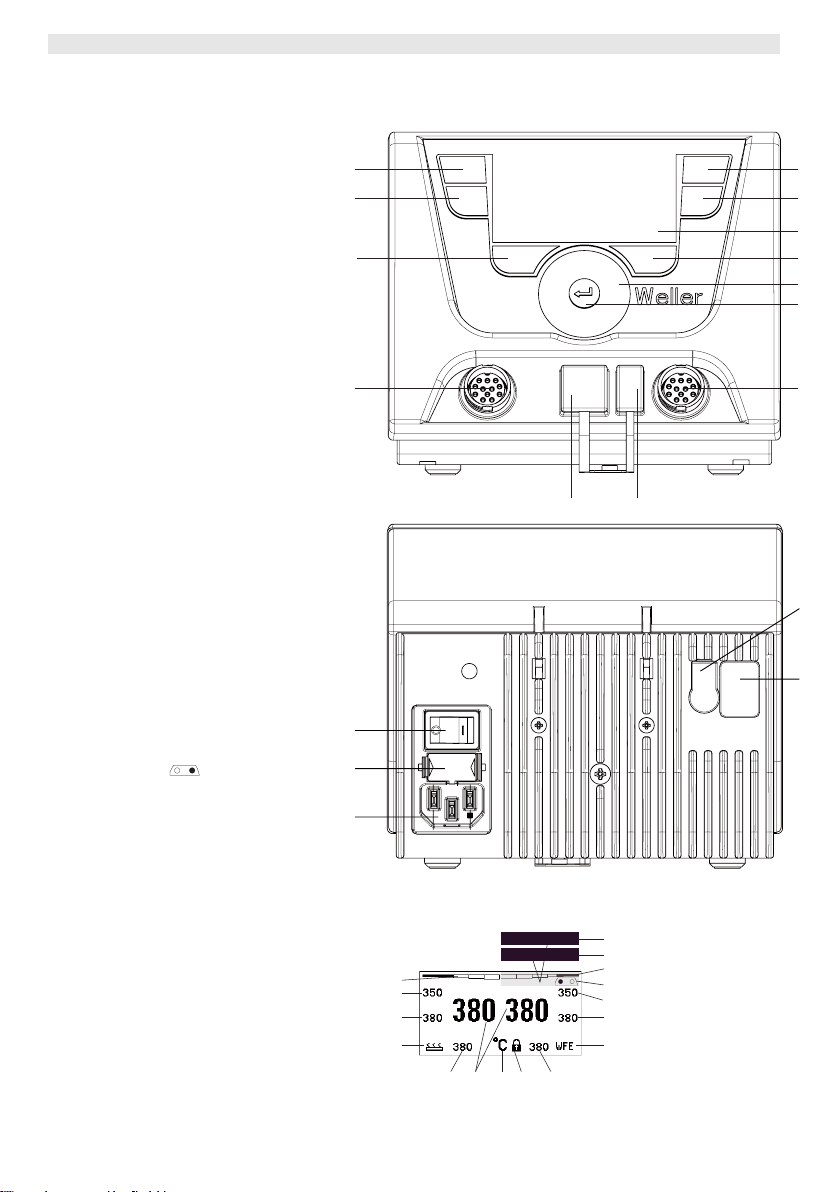
WX 2
WX 2
Hardware Overview
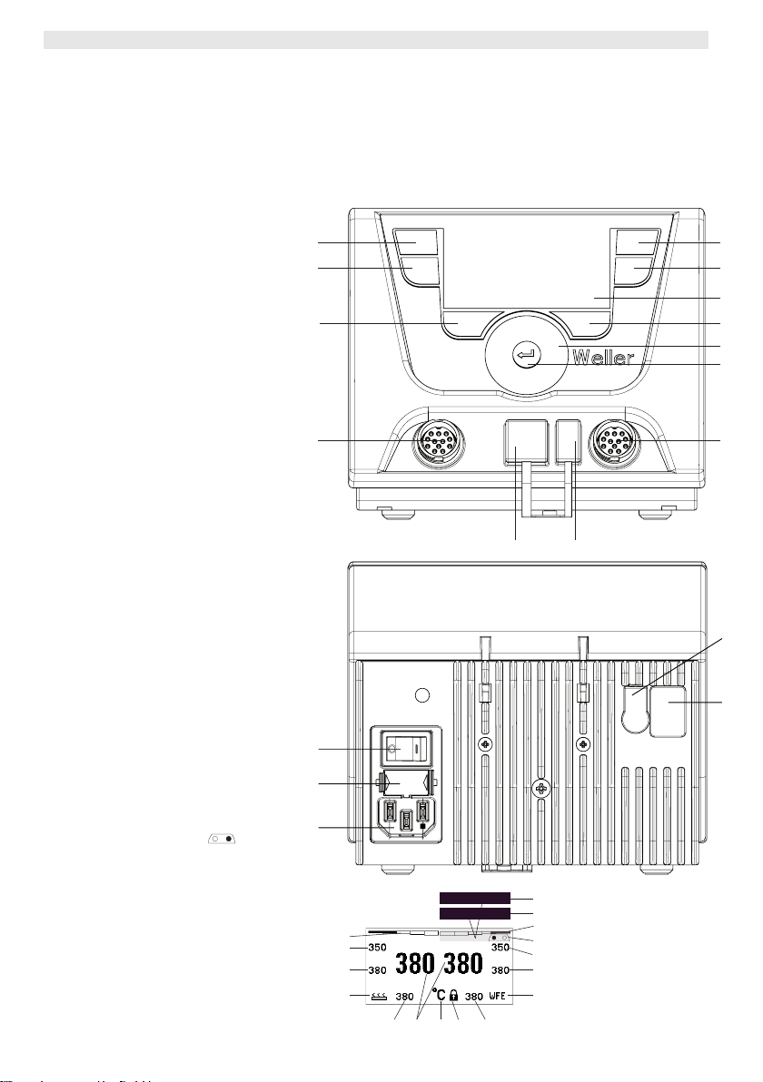
1 Control button, left
2 Control button, left
3 Control button, right
4 Control button, right
5 Display
6 Selection button (set-point
temperature, exit parameter
menu, auxiliary device
parameters)
7 Turn-and-click wheel
8 Enter button
9 Right receptacle for soldering
tool
10 USB port
11 RS232 port
12 Left receptacle for soldering
tool
13 Selection button (nominal
temperature, auxiliary device
parameters)
14 Equipotential bonding bush
15 RS232 port
16 Mains connection
17 Mains fuse
18 Power switch
Display Overview
19 AUTO-OFF
20 Standby temperature
deactivation
21 Power indicator
22 Left (or right
configuration display
23 Fixed temperature 1, right
24 Fixed temperature 2, right
25 Auxiliary device
(rear port)
26 Active set-point/ fixed
temperature, right
27 Lock
28 Temperature units °F/°C
29 Actual tool temperature (left,
right)
30 Active set-point/ fixed
temperature, left
31 Auxiliary device
(front port)
32 Fixed temperature 1, left
33 Fixed temperature 2, left
)
2
1
3
4
5
13
6
7
8
12
9
11 10
14
15
18
17
16
Fig. 1: Hardware Overview
21
33
32
31
O
Standby
29
30 26
27
28
19
20
21
22
23
24
25
Fig. 2: Display Overview
Page 23

WX 2 3-20
Contents
1 About these instructions ............................................................ 3
2 For your safety ........................................................................... 4
3 Included in delivery .................................................................... 4
4 Device description ..................................................................... 5
5 Starting up the device ................................................................ 7
6 Operating the device .................................................................. 8
7 Setting parameters via the parameter menu ............................. 13
8 Care and maintenance of the WX 2 ........................................... 19
9 Error messages and error clearance ......................................... 19
10Accessories ............................................................................... 19
11Disposal ..................................................................................... 20
12Warranty .................................................................................... 20
1 About these instructions
Thank you for placing your trust in our company by purchasing
the Weller WX 2 Soldering Station. The device has been
manufactured in accordance with the most rigorous quality
standards, which ensure that it operates perfectly.
These instructions contain important information which will enable
you to commission, operate and service the WX 2 Soldering Station
safely and correctly as well as to rectify simple problems
yourself.
Z Read these instructions and the accompanying safety information
carefully prior to initial operation and before starting work with the
WX 2 Soldering Station.
Z Keep these instructions in a safe place and so that they are
easily accessible by all users.
DE EN FR IT ES PT NL SV DK FI GR TR CZ PL HU SK SL EE LV LT
1.1 Applied directives
The Weller microprocessor-controlled WX 2 Soldering Station
conforms to the specifications of the EC Declaration of
Conformity with Directives 2004/108/EC and 2006/95/EC.
1.2 Other applicable documents
− Operating instructions of the WX 2 Soldering Station
− Safety information booklet accompanying these instructions
− Operating instructions of the connected tool
(e.g. WXP 120, WXP 200 WXMP or WXMT)
Page 24

4-20 WX 2
2 For your safety
The WX 2 Soldering Station repair system has been manufactured in
accordance with state-of-the-art technology and acknowledged
regulations concerning safety. There is nevertheless the risk of
personal injury and damage to property if you fail to observe the
safety information set out in the accompanying booklet and the
warnings given in these instructions. Always pass on the WX 2
Soldering Station to third parties together with these operating
instructions.
2.1 Intended use
Use the WX 2 Soldering Station only for the purpose indicated in the
operating instructions, i.e. for soldering and desoldering under the
conditions specified herein. Intended use of the WX 2 Soldering
Station also includes the requirement that you
− adhere to these instructions,
− observe all other accompanying documents,
− comply with national accident prevention guidelines applicable at
the place of use.
The manufacturer will not be liable for unauthorised modifications to
the device.
3 Included in delivery
− Soldering Station WX 2
− Power cable
− Operating instructions of the WX 2 Soldering Station
− Safety information booklet accompanying these instructions
Page 25

WX 2 5-20
4 Device description
The Weller WX 2 is a versatile repair station for professional repair
work on state-of-the-art electronic modules in industrial
manufacturing, repair workshops and laboratories.
The digital control electronics in combination with superior sensor
and heat-transfer technology guarantee precise temperature control
at the soldering tip. High-speed measured-value acquisition gives
maximum temperature precision and optimal temperature response
under load.
The temperature can be adjusted within a range of 0 °C – 550 °C
(150 °F – 999 °F) for soldering tools and microtools. Specified and
actual values are displayed digitally. There are four buttons (2 per
tool) for saving fixed temperature presets.
The Weller WX 2 Soldering Station has the following functions and
features:
− Modern operating concept and navigation
− Controlled using sensor buttons
− Multilingual menu navigation
− LC graphic display with blue LED backlighting
− Suitable for all tools up to 200 W or simultaneous
use of 2 x 120 W soldering irons
− No calibration needed
− Two connections for soldering tools with integrated parameter
memory (e.g. for fixed temperature)
− Automatic tool detection and activation of soldering-iron-specific
control parameters
− Digital temperature control
− Antistatic device design in accordance with ESD safety
− Different equipotential-bonding possibilities on the device
(standard configuration: hard grounded)
− Settings for soldering-iron-specific parameters such as: standby
temperature; standby time ; AUTO OFF time; offset; control
response; process window; robot output
− Settings for station-specific parameters such as: language;
temperature version °C/°F; password; touchtones on/off; LCD
contrast; LCD background brightness; screen saver
− Two connections for peripheral devices (e.g. WFE, WHP)
− Digital and optically decoupled robot connection
− USB port for memory stick (for firmware updates, configuration
and monitoring)
DE EN FR IT ES PT NL SV DK FI GR TR CZ PL HU SK SL EE LV LT
Page 26
6-20 WX 2
A
Technical data of WX 2
Dimensions L x W x H (mm): 170 x 151 x 130
L x W x H (inches): 6.69 x 5.94 x 5.12
Weight approx. 3.2 kg
Mains supply voltage 230 V, 50 Hz
Power consumption 200 W (240 W)
Safety class I, antistatic housing
Fuse Overcurrent trip T2 A
Temperature range Adjustable from
50 °C – 550 °C (150 °F – 999 °F)
Controllable temperature range is
tool-dependent
Temperature accuracy ± 9 °C (± 17 °F)
Temperature stability ± 2 °C (± 4 °F)
Equipotential bonding Via 3.5 mm pawl socket on back of
device
Housing material Aluminium base
with antistatic black
(AMS 70002) coating; antistatic PA
plastic housing
Operator panel material
ntistatic-coated real glass
Operator panel dimensions 74 x 38 mm
Resolution 255 x 127 (128) dots
Backlighting 4 LEDs
a
b
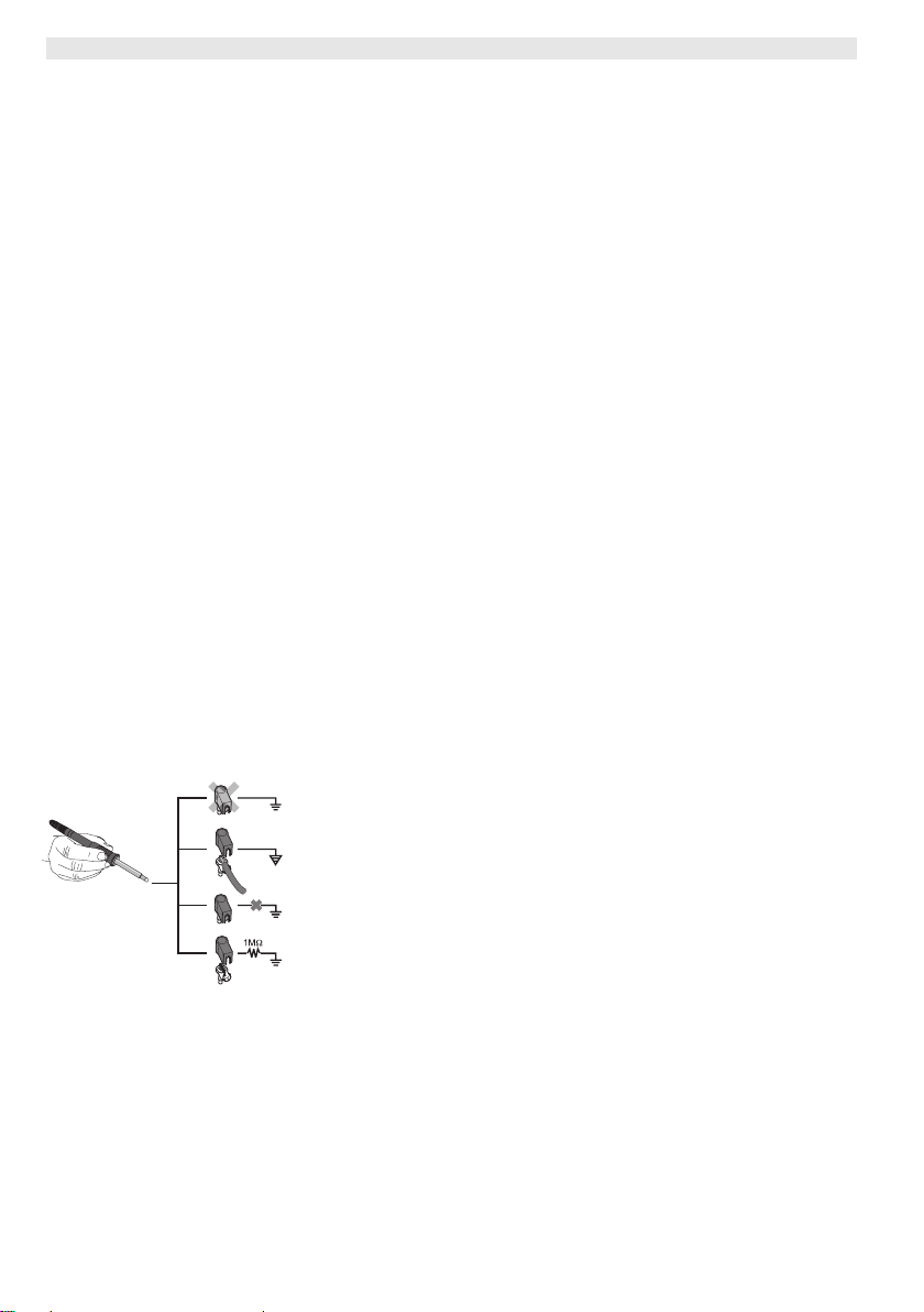
Equipotential bonding
Four variants are possible by connecting the 3.5 mm jack socket
(14) differently:
− (a) Hard-grounded: supplied without plug.
− (b) Equipotential bonding: with plug, equaliser at centre contact.
c
− (c) Floating: with plug
− (d) Soft-grounded: with plug and soldered resistor. Grounded
d
through selected resistor.
Fig. 3
USB port
The WX 2 control unit comes with a front-side USB port (10) for
installing firmware updates, configuration and monitoring. The USB
port (10) accepts any commercial USB memory stick.
Page 27
WX 2 7-20
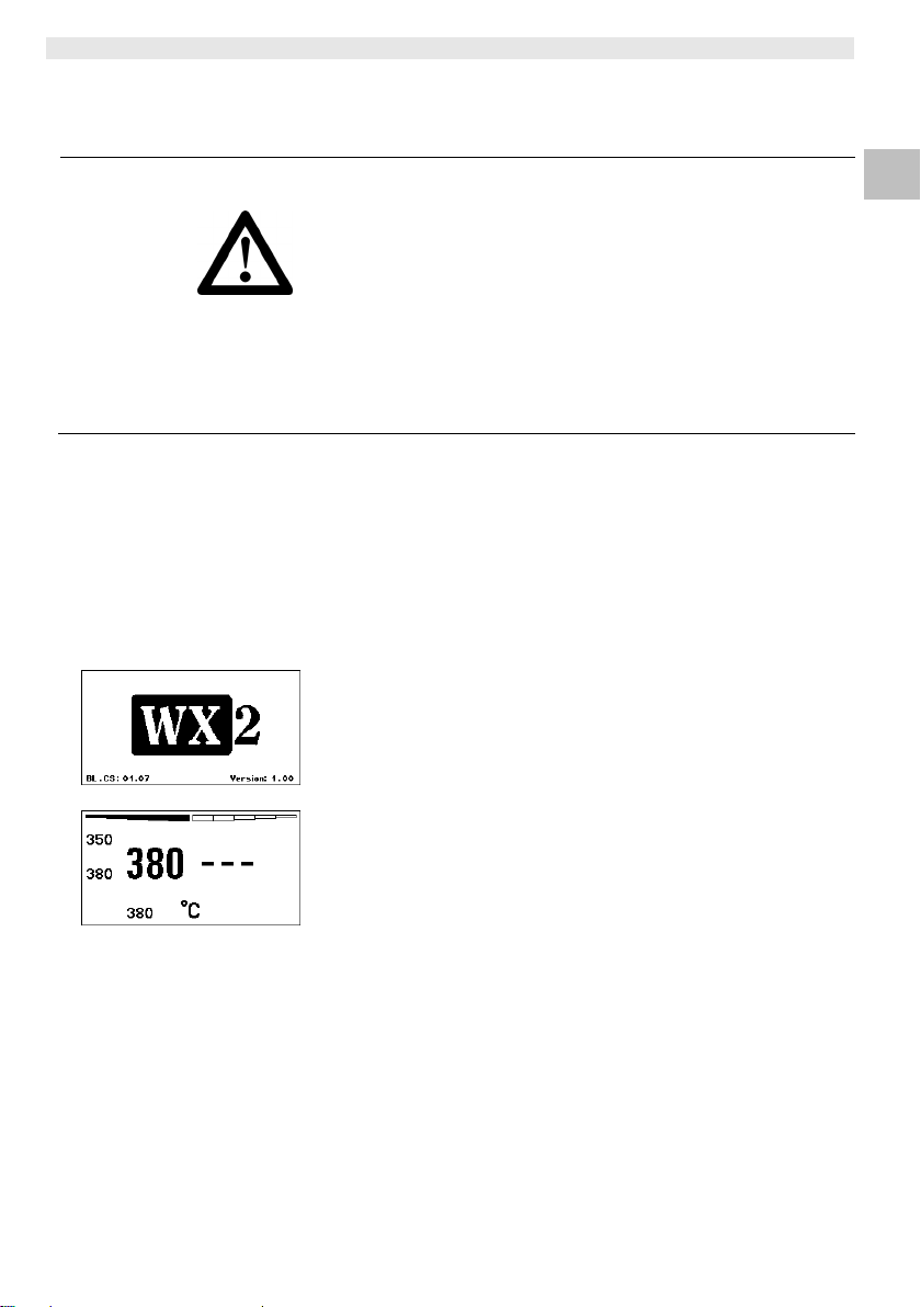
Fig. 4
Fig. 5
WARNING!
Note Only soldering tools with suitable connecting plugs can be
5 Starting up the device
Electric shock and risk of burns
Connecting the control unit incorrectly poses a risk of injury due to
electric shock and can damage the device. Risk of burns from the
soldering tool while the control unit is operating.
Z Read the enclosed instructions, the safety instructions included
in these operating instructions as well as the instructions for
your control unit all the way through and observe the specified
precautionary measures before putting the control unit into
operation.
Z Always place the soldering tool in the safety holder when not in
use.
Please observe the overview diagrams (Fig. 1 and Fig. 2).
connected to the WX 2 Soldering Station.
For details of tools which can be connected to WX 2, please refer to
the list of accessories on page 19.
1. Carefully unpack the device.
2. Connect the soldering tools as follows:
Insert the soldering tool with connector into the connecting socket
(9/12) on the control unit and turn clockwise to lock.
3. Place the soldering tool in the holder.
4. Check to make sure that the mains supply voltage matches that
indicated on the rating plate and that the mains power switch (18)
is off.
5. Connect the control unit to the mains supply (16).
6. Switch on the device at the mains power switch (18).
The start-up screen is shown on the display (see Fig. 4).
After switching on the device, the microprocessor carries out a selftest and reads out the values of the parameters stored in the tool.
When a soldering iron is connected, the display shows the set
temperature (set-point, 30/26), the temperature units °C/°F (28), the
actual value (actual tool temperature) (29) and the saved fixed
temperatures (33/32/23/24).
DE EN FR IT ES PT NL SV DK FI GR TR CZ PL HU SK SL EE LV LT
Page 28
8-20 WX 2
f
6 Operating the device
6.1 Operating principle
2
1
13
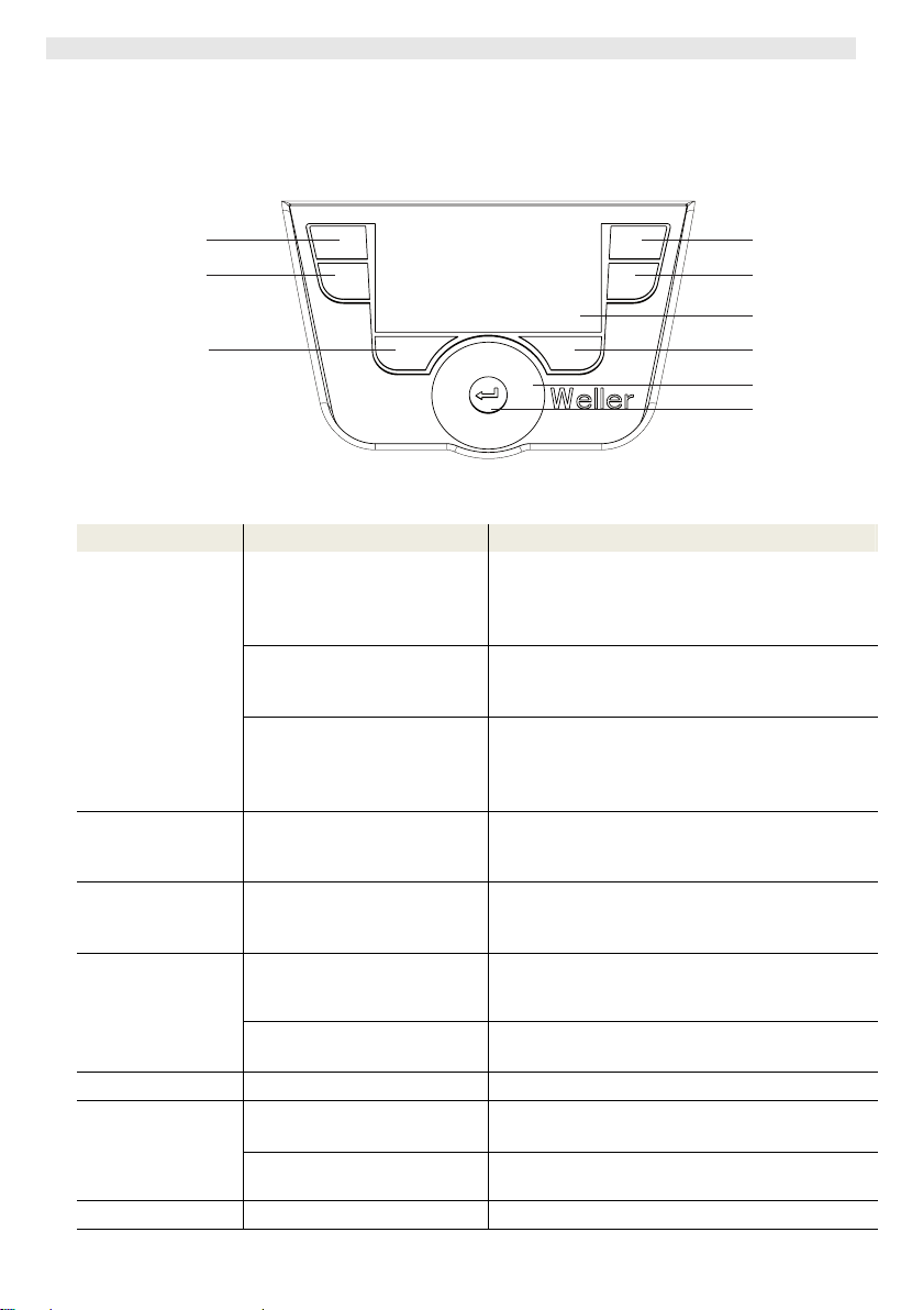
Fig. 6: Control elements on the WX 2
Keys Operation Function
Control key 1, 2, 3, 4 Briefly press key 1, 2, 3 or 4
once
The fixed temperature (23/24/32/33)* becomes
the active set-point temperature (26/30)*.
(tool channel: key 1, 2 = left; key 3, 4 = right)
− Scroll within the Parameter menu
Press and hold down key 1, 2,
3 or 4
for 3 sec.
Press and hold down keys 1
and 2 or 3 and 4
simultaneously
− The active set-point temperature is saved as
the fixed temperature under the key being
pressed (1, 2, 3 or 4).
− 1 and 2 = left channel (12)* is disabled or
opened
− 3 and 4 = right channel (9)* is disabled or
opened
Press and hold
down keys 13 and 1
keys 13 and 1 or 13 and 2
simultaneously
− Open Parameter menu
or 2
Press and hold
down keys 6 and 3
keys 6 and 3 or 6 and 4
simultaneously
− Open Parameter menu
or 4
Selection key 6, 13 Briefly press key 6 or 13 once
− Select auxiliary device, this being a
requirement for opening the parameter
settings of the auxiliary device (e.g. WFE)
Press and hold down keys 6
− The set-point temperature window opens
and 13 for 3 sec.
Key 6 Brie
Turn-and-click
wheel 7
ly press key 6 once
Move your finger over the
turn-and-click wheel
Click left or right
− Exit parameter menu
− Select/set value
− Navigate within a menu
− The set-point temperature window opens for
the soldering tool connected on the left/right
Enter key 8 Briefly press key 8 once
− Confirm value/selection
*) see also overview diagrams (Fig. 1 and Fig. 2).
3
4
5
6
7
8
Page 29
WX 2 9-20
Fig. 7
Fig. 8
Fig. 9
Fig. 10
6.2 Example 1:
adjusting the temperature
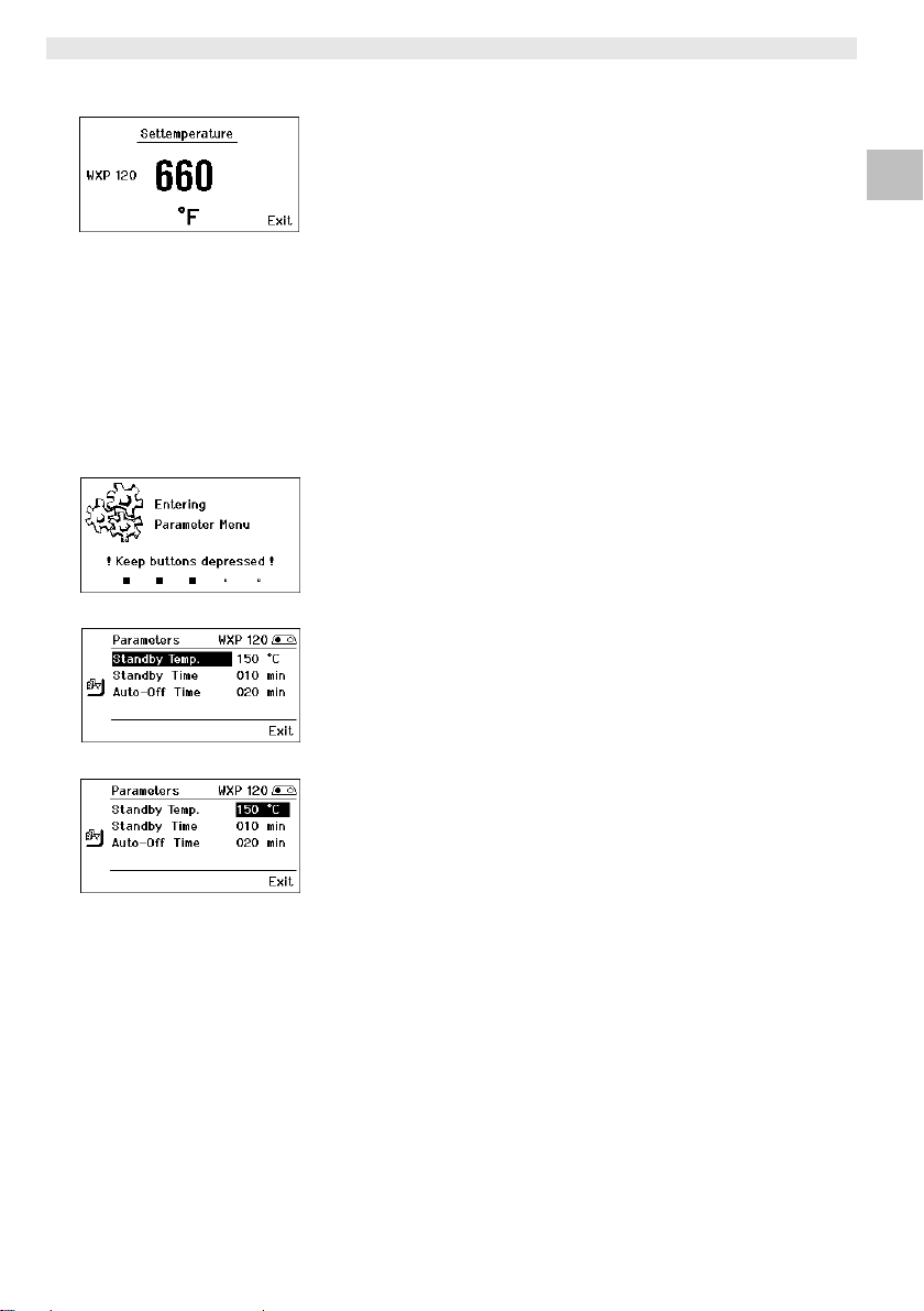
1. Press and hold down the required selection key 6 or 13 for 3 sec.
The display changes over to the set-point temperature
(see Fig. 7).
2. Set the required set-point temperature with the turn-and-click
wheel (7).
3. Confirm the value with the Enter key (8).
4. Exit the parameter menu with key 6.
Note If no entry is made for 10 seconds, the parameter menu is exited
automatically.
6.3 Example 2:
Call up parameter menu and select menu option
1. Press and hold down keys 13 and 1 or 13 and 2 or 6 and 3 or 6
and 4 simultaneously.
While the device is changing over to the parameter menu, the
display shows the following message text (see also Fig. 8):
"Changing over to parameter menu" "Hold down keys".
2. Select menu option with the turn-and-click wheel (7).
The selection is shown with a black background (e.g. "Standby
Temp.", see Fig. 9).
3. Confirm the selection with the Enter key (8).
The display changes over to Selection/Entry mode (see Fig. 10).
4. Make your setting with the turn-and-click wheel (7).
5. Confirm the setting with the Enter key (8).
The setting is made and the parameter menu is displayed.
6. Select a new menu option with the turn-and-click wheel (7) and
set the required value (see steps 3.-5.)
– or –
exit the parameter menu with key 6.
DE EN FR IT ES PT NL SV DK FI GR TR CZ PL HU SK SL EE LV LT
Page 30
10-20 WX 2
6.4 Connecting the soldering tool
Please observe the overview diagrams (Fig. 1 and Fig. 2).
1. Check to see if the required soldering tool is correctly connected
(see "Starting up the device" on page 7).
2. Switch on the device at the mains power switch (18).
The display shows the actual temperature value (29), the setpoint temperature (26/30) and the fixed temperatures (23/24 or
32/33) of the connected tool. The set-point temperature and fixed
temperatures are stored in the tool. The actual temperature value
increases to the set-point temperature (= soldering tool is heated
up).
Note If you want to connect two tools simultaneously to WX 2, please
note the overload cut-out.
Note
You will find further connection versions on page 21.
Please adhere to the operating instructions of the connected
devices.
Fig. 11: WX 2 with
connected soldering
tool
Fig. 12
Overload cut-out (240 W)
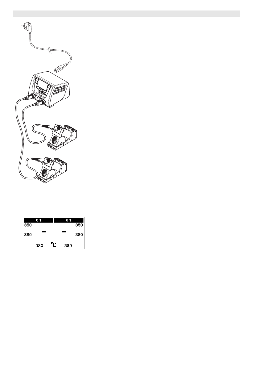
If two tools are simultaneously connected to WX 2 and together have
a power demand of greater than 240 W, an overload cut-out will
occur (see Fig. 12).
Only one tool/channel can be used at a time.
Activating the soldering tool/channel:
Z Press the required control keys 1 and 2 (left channel (12)) or 3
and 4 (right channel (9)) simultaneously.
– or–
Remove the required soldering iron from its holder.
Page 31
WX 2 11-20
Fig. 13
6.5 Setting the temperature individually
Please observe the overview diagrams (Fig. 1 and Fig. 2).
Setting the fixed temperature
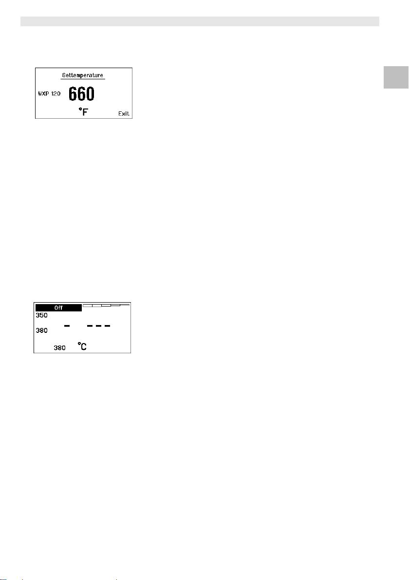
1. Press the required selection key 6 or 13.
The current set-point temperature is shown on the display (see
Fig. 13).
2. Set the required set-point temperature with the turn-and-click
wheel (7).
3. Confirm the value with the Enter key (8).
4. Press and hold down the required control key 1, 2, 3 or 4 for
3 sec. in order to save the current set-point as a fixed
temperature (under the key being pressed).
Note You can find further information about the intelligent tool (e.g. fixed
temperature, factory settings) in the relevant operating instructions.
Select the temperature with control keys 1, 2, 3 and 4
The temperature set-point can be set by selecting two preset
temperature values (fixed temperatures) per tool.
Z Press the required temperature key 1, 2, 3 and 4.
The tool adjusts to the required temperature.
6.6 Switching the channel on/off
Please observe the overview diagrams (Fig. 1 and Fig. 2).
Left channel (12)
Z Press control keys 1 and 2 simultaneously to switch the tool
on/off.
DE EN FR IT ES PT NL SV DK FI GR TR CZ PL HU SK SL EE LV LT
Fig. 14
Right channel (9)
Z Press control keys 3 and 4 simultaneously in order to switch the
tool on/off.
Note The tool is switched on as soon it is removed from the holder. A
motion sensor is integrated in the tool.
Channel disabled
If a channel is disabled, the display will read "OFF" (19).
Page 32

12-20 WX 2
6.7 Soldering and desoldering
Z Carry out soldering work as directed in the operating instructions
of your connected soldering tool.
Handling soldering tips
− Coat the tin-plated soldering tip with solder when heating the iron
for the first time as this will remove any oxide films or impurities
from the soldering tip that have accumulated during storage.
− During pauses between soldering and before storing the soldering
iron, ensure that the soldering tip is well-coated.
− Do not use aggressive fluxing agents.
− Always make sure that the soldering tip is seated correctly.
− Select the lowest possible working temperature.
− Select the largest possible soldering tip shape for the application:
approx. as large as the soldering pad.
− Coat the soldering tip well to ensure efficient heat transfer
between the soldering tip and soldering point.
− Switch off the system if you do not intend to use the soldering iron
for lengthy periods or activate the Weller temperature reduction
function.
− Wet the tip with solder if you do not intend to use the soldering
iron for a lengthy period of time.
− Apply the solder directly at the soldering point, not on the
soldering tip.
− Change the soldering tip using an appropriate tool.
− Do not subject the soldering tip to physical force.
Note The control units have been adapted to hold a medium-sized
soldering tip. Discrepancies may occur if the tip is changed or a
different shaped tip is used.
Page 33
WX 2 13-20
7 Setting parameters via the parameter
menu
The parameter menu is subdivided into two areas:
Parameter
Setting options:
- Standby temperature
- Standby time (temperature deactivation)
- AUTO OFF time (automatic switch-off time)
- Offset (temperature offset)
- Control response
- Process window
Station parameters
Setting options:
- Language
- Temperature version °C/°F (temperature units)
- Password (lock function)
- Touchtones on/off
- LCD contrast
- LCD background brightness
- Screen saver
7.1 Set parameters
Please observe the overview diagrams (Fig. 1 and Fig. 2).
DE EN FR IT ES PT NL SV DK FI GR TR CZ PL HU SK SL EE LV LT
Fig. 15
Fig. 16
Setting the standby temperature
Note The soldering tools have a usage detector (sensor) in the handle
which automatically starts the cooling cycle when the soldering tool
is not in use.
You will find further information about the intelligent tool in the
relevant operating instructions.
The standby temperature is automatically set after a temperature
deactivation.
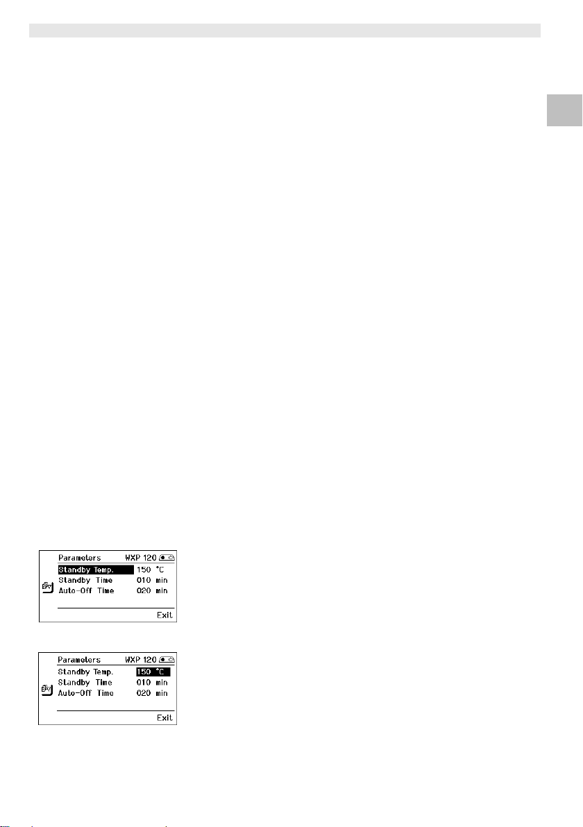
1. Call up the parameter menu.
2. Select the menu option Standby temperature.
3. Set the standby temperature set-point with the turn-and-click
wheel (7).
4. Confirm the value with the Enter key (8).
5. Exit the parameter menu with key 6.
Page 34
14-20 WX 2
Set the temperature deactivation value (standby time)
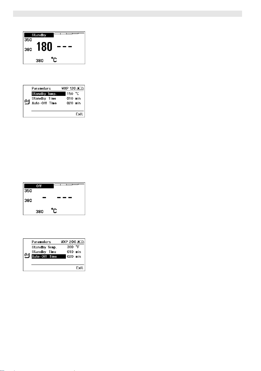
When the soldering tool is not in use, the temperature is reduced to
the standby temperature after the set standby time has elapsed.
Standby mode is indicated as a flashing actual value and the display
reads "Standby" (20).
Fig. 17
Fig. 18
Fig. 19
Fig. 20
Press control key 1, 2, 3 or 4 to exit Standby mode. The sensor
integrated tool detects the change in state and deactivates Standby
mode as soon as the tool is moved.
Setting the standby time:
1. Call up the parameter menu.
2. Select and confirm the menu option Standby time.
3. Set the required standby time with the turn-and-click wheel (7).
The following standby settings are possible:
− "OFF" = "0 min": standby time is deactivated (factory setting)
− "ON" = "1-99 min": standby time, individually adjustable
4. Confirm the value with the Enter key (8).
Select further setting parameters in the menu
or
exit the parameter menu with key 6.
Note In the case of soldering work with low heat requirements, the
reliability of the standby function may be impaired.
Setting the automatic switch-off time (AUTO-OFF)
When the soldering tool is not in use, the soldering tool
heater is switched off when the AUTO OFF time expires.
Temperature deactivation is performed independently of the set
standby function. The actual temperature is indicated by flashing
LED and serves as a residual heat display. The display reads
"OFF" (19).
1. Call up the parameter menu.
2. Select and confirm the menu option AUTO-OFF time .
3. Set the required AUTO-OFF time with the turn-and-click wheel
(7).
The following AUTO-OFF time settings are possible:
− "OFF" = "0 min": AUTO OFF function is deactivated (factory
setting)
− "ON" = "1-999 min": AUTO-OFF time, can be set individually.
4. Confirm the period with the Enter key (8).
Select further setting parameters in the menu or
exit the parameter menu with key 6 .
Note To reset the STANDBY and AUTO-OFF modes:
Press control key 1,
the soldering tool from the holder.
2, 3 or 4 (if no
tool holder is in use) or remove
Page 35
WX 2 15-20
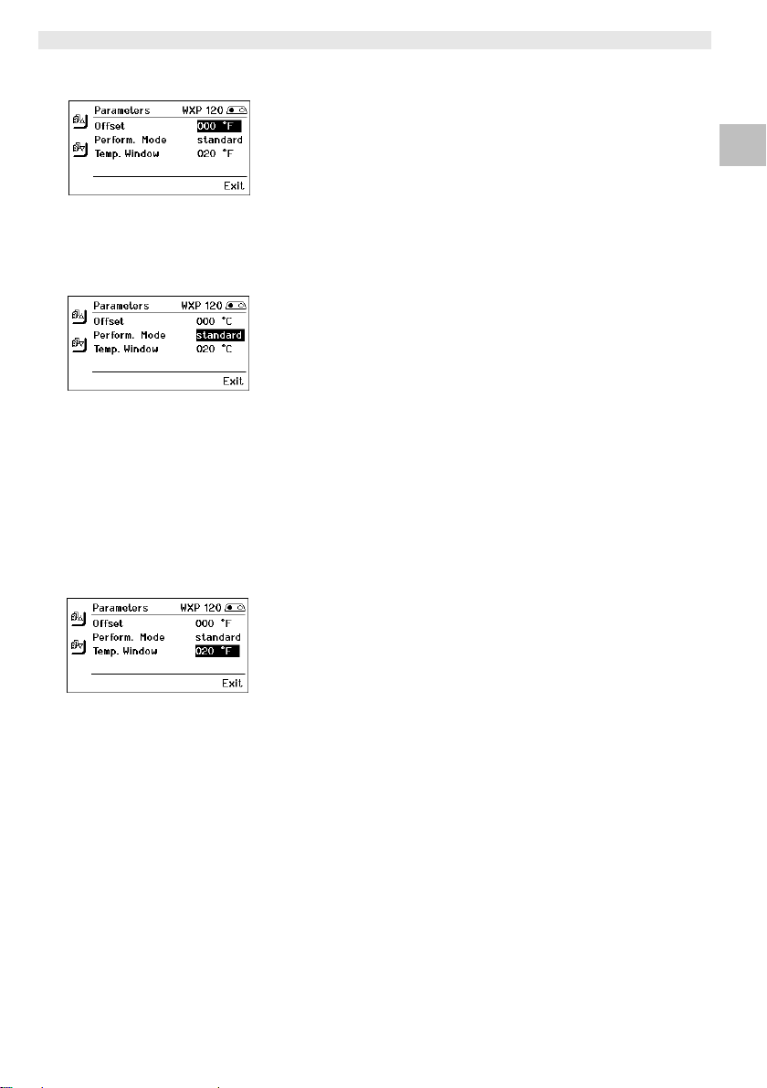
Fig. 21
Fig. 22
Fig. 23
Setting the temperature offset
The actual soldering-tip temperature can be adapted by entering a
temperature offset around ± 40 °C (± 72 °F).
1. Call up the parameter menu.
2. Select and confirm the menu option OFFSET.
3. Set the required OFFSET temperature with the turn-and-click
wheel (7).
4. Confirm the value with the Enter key (8).
Select further setting parameters in the menu or
exit the parameter menu with key 6.
Setting the control response
The function determines the heating characteristics of the soldering
tool to achieve the set tool temperature.
1. Call up the parameter menu.
2. Select and confirm the menu option Control response.
3. Set the required control function with the turn-and-click wheel (7).
The following settings are possible:
− "standard": adapted (medium) heating (factory setting)
− "soft": slow heating
− "aggressive": rapid heating
4. Confirm the setting with the Enter key (8).
Select further setting parameters in the menu or
exit the parameter menu with key 6.
Setting the process window
The temperature range set in the process window determines the
signal response of the floating switching output.
1. Call up the parameter menu.
2. Select and confirm the menu option Process window.
3. Set the required temperature range of the process window with
the turn-and-click wheel (7).
4. Confirm the value with the Enter key (8).
Select further setting parameters in the menu or
exit the parameter menu with key 6 .
DE EN FR IT ES PT NL SV DK FI GR TR CZ PL HU SK SL EE LV LT
Note On tools with an LED ring light ( e.g. WXP 120), the process
window defines the illumination characteristics of the LED ring light.
− If the LED is continuously illuminated, this means that the
preselected temperature has been reached or that the
temperature is within the predetermined process window.
− A flashing LED indicates that the system is heated or that the
temperature is outside the process window.
Page 36
16-20 WX 2
7.2 Setting the station parameters
Please observe the overview diagrams (Fig. 1 and Fig. 2).
Selecting the menu navigation language
1. Call up the parameter menu.
2. Select and confirm the menu option Language.
3. Set the required language with the turn-and-click wheel (7).
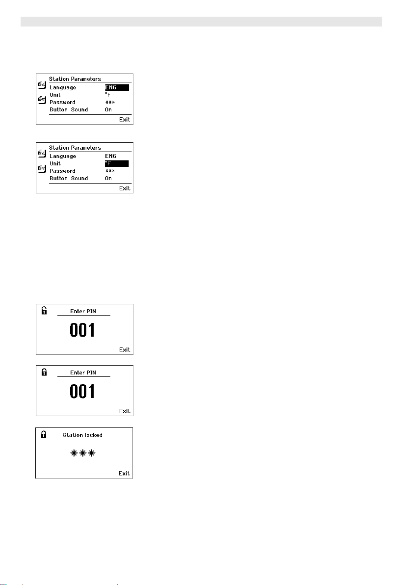
Fig. 24
Fig. 25
4. Confirm the value with the Enter key (8).
Changing the temperature units display
1. Call up the parameter menu.
2. Select and confirm the menu option Temperature units °C/°F.
3. Set the required temperature units with the turn-and-click
wheel (7).
4. Confirm the setting with the Enter key (8).
Switching the lock function on/off
After switching the lock function on, only the fixed temperature keys
(= control keys 1, 2, 3 and 4) can be operated on the soldering
station. All other settings are disabled until the repair station is
unlocked again.
Note If you want only one temperature value to be selectable, the control
keys 1, 2 and/or 3, 4 (fixed temperature keys) must be set to the
same temperature value.
Fig. 26
Fig. 27
Fig. 28
Lock the soldering station:
1. Call up the parameter menu.
2. Select and confirm the menu option Password.
3. Set the required three-character locking code
(between 001-999) with the turn-and-click wheel (7) (see Fig. 26).
4. Confirm the value with the Enter key (8).
The lock is active (the display shows a lock symbol (27), see also
Fig. 27).
Unlocking the soldering station
1. Call up the parameter menu.
If the lock function is active, the password menu item opens
automatically. Three stars (***) are shown on the display.
2. Set the three-character locking code using the turn-and-click
wheel (7).
3. Confirm the code with the Enter key (8).
Page 37
WX 2 17-20
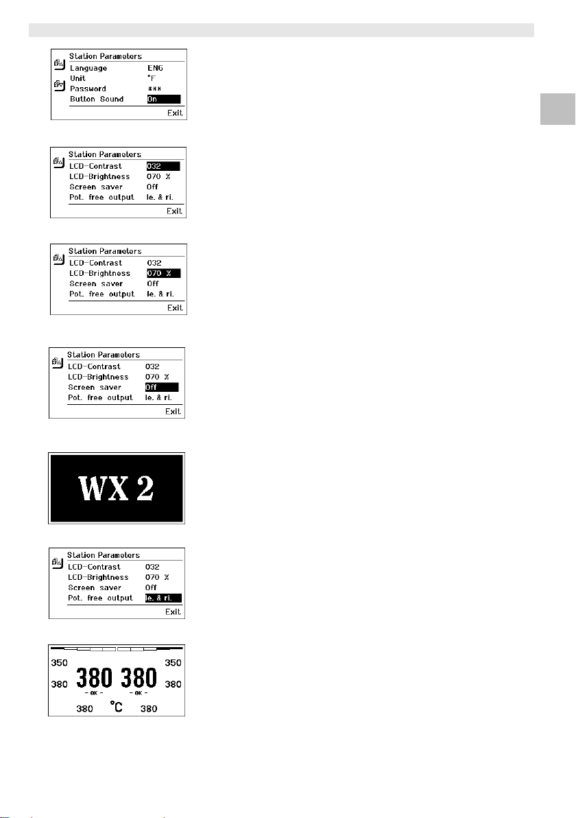
Fig. 29
Fig. 30
Fig. 31
Fig. 32
Switching touchtones on/off
1. Call up the parameter menu.
2. Select and confirm the menu option Touchtones.
3. Switch touchtones on or off with the turn-and-click wheel (7).
4. Confirm the setting with the Enter key (8).
Setting the LCD contrast
1. Call up the parameter menu.
2. Select and confirm the menu option LCD contrast.
3. Set the required LCD contrast value with the turn-and-click
wheel (7).
4. Confirm the value with the Enter key (8).
Setting the LCD background brightness
1. Call up the parameter menu.
2. Select and confirm the menu option LCD background brightness.
3. Set the required LCD background brightness with the turn-andclick wheel (7).
4. Confirm the value with the Enter key (8).
Setting the screen saver
1. Call up the parameter menu.
2. Select and confirm the menu option Screen saver.
3. Switch the screen saver on or off with the turn-and-click
wheel (7).
4. Confirm the value with the Enter key (8).
DE EN FR IT ES PT NL SV DK FI GR TR CZ PL HU SK SL EE LV LT
Fig. 33
Fig. 34
Fig. 35
Defining the robot output
The robot output is on the back of the device (15). The pin
assignments of the robot output are shown on page 21. The left tool
channel is assigned to the robot output in the basic settings, but the
assignments can be changed manually.
1. Call up the parameter menu.
2. Select and confirm the menu option Robot output.
3. Select the tool channel(s) with the turn-and-click wheel (7).
The following robot output settings are possible:
− "left": left tool channel (factory setting)
− "right": right tool channel
− "left & right": both tool channels
4. Confirm the setting with the Enter key (8).
Note If the robot is at working temperature, the display will show – ok -
(see Fig. 34).
Page 38
18-20 WX 2
7.3 Carrying out a firmware update
1. Switch off the WX 2 Soldering Station.
2. Insert the memory stick into the USB port.
3. Switch on the WX 2 Soldering Station.
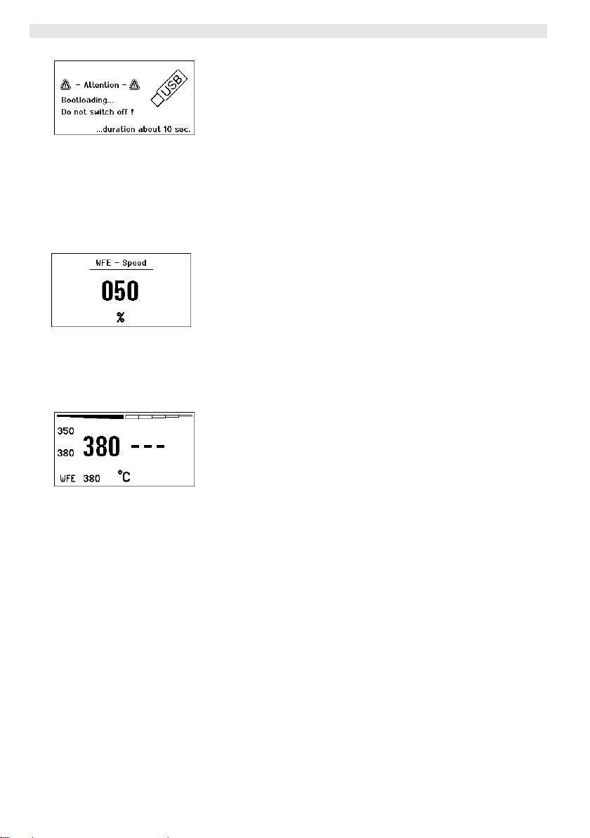
Fig. 36
Note The station must not be switched off while the firmware update is
The firmware update is performed automatically (see Fig. 36).
If you have a more already installed more recent firmware on your
station, this will not be changed.
running.
7.4 Connecting auxiliary devices
Please observe the overview diagrams (Fig. 1 and Fig. 2).
Auxiliary devices can be connected either to the port on the front
panel (11) and/or to the port on the back (15) of the WX 2 Soldering
Station.
Fig. 37
The WX 2 Soldering Station detects automatically which auxiliary
device is connected. The WX 2 Soldering Station shows the symbol
or name of the connected auxiliary device (31/25) on the left (front
port (11), see Fig. 38) or right (rear port).
7.5 Setting the parameters of auxiliary devices
Please observe the overview diagrams (Fig. 1 and Fig. 2).
1. Select the auxiliary device using the auxiliary device key
(front/back) (6, 13).
The variable parameters (e.g. speed) are displayed.
2. Set the required value using the turn-and-click wheel (7).
Fig. 38: front WFE
connection
3. Confirm the value with the Enter key (8)
or
press key 6 to exit.
Page 39

WX 2 19-20
8 Care and maintenance of the WX 2
Z Clean the operator panel, if dirty, using a suitable cleaning cloth.
Z Seal ports which are not in use with covering caps.
9 Error messages and error clearance
Message/symptom Possible cause Remedial measures
Display: "- - -
No display function
(display OFF)
OFF
Channel cannot be switched
on
− Tool has not been detected
− Tool defective
− No mains supply voltage − Turn on mains power switch
− Overload cut-out − Only one soldering iron can be
− Check connection of tool to
device
− Check connected tool
− Check mains supply voltage
− Check device fuse
operated.
10 Accessories
T005 29 202 99 WXP 120 Soldering set with holder WDH 10
T005 29 206 99 WXP 200 Soldering set with holder WDH 31
T005 13 178 99 WXMT Micro desoldering tweezers with holder
WDH 60
T005 29 204 99 WXMP Micro soldering iron with holder WDH 50
T005 15 121 99 WDH 10 Safety holder for WXP 120
T005 15 158 98 WDH 31 Safety holder for WXP 200
T005 15 156 99 WDH 50 Safety holder for WXMP
T005 15 169 99 WDH 60 Safety holder for WXMT
T005 36 476 99 WFE 20D 230 V solder fume extractor
T005 36 266 99 WFE 2S 230 V portable extractor unit
T005 36 256 99 WFE 4S 230 V mobile extractor unit
T005 36 586 99 WFE 8S 230 V mobile extractor unit
T005 33 648 99 WHP 1000 1000 W preheating plate
T005 33 386 99 WHP 3000 600 W infrared preheating plate
T005 33 646 99 WHP 3000 1200 W infrared preheating plate
T005 87 647 10 WX Connecting cable
T005 87 647 11 WX PC adaptor
T005 87 647 12 WX Adaptor for WFE/WHP
For details of other accessories, please refer to the operating
instructions for the individual soldering iron sets.
DE EN FR IT ES PT NL SV DK FI GR TR CZ PL HU SK SL EE LV LT
Page 40

20-20 WX 2
11 Disposal
Dispose of replaced equipment parts, filters or old devices in
accordance with the rules and regulations applicable in your country.
12 Warranty
Claims by the buyer for physical defects are time-barred after a
period of one year from delivery to the buyer. This does not apply to
claims by the buyer for indemnification in accordance with §§ 478,
479 BGB (German Federal Law Gazette).
We shall only be liable for claims arising from a warranty furnished
by us if the quality or durability warranty has been furnished by use
in writing and using the term "Warranty“.
In addition, for the USA and Canada:
Cooper Tools warrants to the original purchaser and any subsequent
owner (“Buyer”) that Weller soldering and desoldering products will
be free from defects in material and workmanship for a period of one
year from date of purchase, provided that no warranty is made with
respect to products which have been altered, subjected to abuse or
improperly used, installed or repaired. Use of non-Cooper Tools
components will void this warranty if a non-Cooper Tools component
is defective (or is the source of the defect). Cooper Tools will repair
or replace products found to be defective not caused by a part,
component or accessory manufactured by another company, during
the warranty period. Contact Cooper Tools with dated proof of
purchase and return to Apex Tool Group, LLC., 14600 York Rd. Suit
A, Sparks, MD 21152. All costs of transportation and reinstallation
shall be borne by the Buyer.
IN NO EVENT SHALL COOPER TOOLS BE LIABLE FOR
INCIDENTAL OR CONSEQUENTIAL DAMAGES. COOPER TOOLS
LIABILITY FOR ANY CLAIMS ARISING OUT OF THIS WARRANTY
SHALL NOT EXCEED THE PURCHASE PRICE OF THE
PRODUCT.
THE PERIOD OF ALL IMPLIED WARRANTIES APPLICABLE TO
THIS PRODUCT INCLUDING ANY IMPLIED WARRANTY OF
MERCHANTABILITY OR FITNESS, OR FITNESS FOR A
PARTICULAR PURPOSE IS LIMITED TO 12 MONTHS FROM THE
DATE OF PURCHASE BY THE USER.
Some states do not allow the exclusion or limitation of incidental or
consequential damages, so the above limitation or exclusion may
not apply to you. Some states do not allow limitation on how long an
implied warranty lasts, so the above limitation may not apply to you.
This warranty gives you specific legal rights, and you may also have
other rights, which vary from state to state.
Subject to technical alterations and amendments!
Updated operating instructions are available for download at
www.weller.eu.
Page 41

WX 2
Manual de uso
DE
EN
ES IT ES
PT NL SV DK FI GR TR CZ PL HU SK SL EE LV LT
Page 42
WX 2
WX 2
Componentes
principales del
aparato
1 Tecla de mando izquierda
2 Tecla de mando izquierda
3 Tecla de mando derecha
4 Tecla de mando derecha
5 Pantalla
6 Selector (temperatura de
referencia, salir del menú de
parámetros, parámetros
equipo adicional)
7 Selector giratorio
8 Tecla Enter
9 Conector hembra derecho
para el soldador
10 Interfaz USB
11 Interface RS232
12 Conector hembra izquierdo
para el soldador
13 Selector (temperatura de
referencia, parámetros
equipo adicional)
14 Conector hembra
equipotencial
15 Interface RS232
16 Conector principal
17 Fusible
18 Interruptor principal
29 Temperatura actual del soldador (derecha, izquierda)
30 Valor de referencia activo/ Temperatura fija izquierda
31 Equipo adicional
(interfaz en parte delantera)
32 Temperatura fija 1, izquierda
33 Temperatura fija 2, izquierda
2
1
13
12
11 10
3
4
5
6
7
8
9
14
Indicadores
principales de la
pantalla
19 AUTO-OFF
20 Standby Desconexión de la
temperatura
21 Indicador de potencia
22 Indicador Parametrización
izquierda (o derecha
23 Temperatura fija 1, derecha
24 Temperatura fija 2, derecha
25 Equipo adicional
(interfaz en parte trasera)
26 Valor de referencia activo/
Temperatura fija derecha
27 Bloqueo
28 Unidad de medición de la
temperatura °F/°C
)
18
17
16
21
33
32
31
O
Standby
29
30 26
27
28
19
Fig. 1: Componentes
20
principales del aparato
21
22
23
24
25
Fig. 2: Indicadores principales de la
pantalla
15
Page 43

WX 2 3-20
Índice
1 Sobre estas instrucciones .......................................................... 3
2 Por su propia seguridad ............................................................. 4
3 Piezas suministradas ................................................................. 4
4 Descripción del aparato ............................................................. 5
5 Puesta en servicio del aparato .................................................. 7
6 Manejo del aparato .................................................................... 8
7 Ajuste de los parámetros a través del menú de parámetros ..... 13
8 Cuidado y mantenimiento de la estación WX 2 ......................... 19
9 Mensajes de error y su reparación ............................................ 19
10Accesorios ................................................................................. 19
11Eliminación de residuos ............................................................. 20
12Garantía ..................................................................................... 20
1 Sobre estas instrucciones
Le agradecemos la confianza depositada en nosotros con la
adquisición de la estación de soldar WX 2. La fabricación de este
aparato está sometida a los más rigurosos controles de calidad para
garantizar un perfecto funcionamiento del mismo.
Este manual contiene información importante para facilitarle la
puesta en servicio, el manejo y el mantenimiento de su estación de
soldar WX 2, así como para permitir que usted mismo sea capaz de
eliminar por su cuenta anomalías sencillas.
Z Lea por completo este manual y las siguientes instrucciones de
seguridad antes de la puesta en servicio del aparato y antes de
comenzar a trabajar con la estación de soldar WX 2.
Z Mantenga este manual de uso en un lugar al que puedan
acceder todos los usuarios del aparato.
DE EN ES IT PT NL SV DK FI GR TR CZ PL HU SK SL EE LV LT
1.1 Directivas aplicables
La estación de soldar WX 2 con control por microprocesador es
conforme a la Declaración de conformidad CE con las Directivas
2004/108/CE y 2006/95/CE.
1.2 Otros documentos aplicables
− Manual de uso de la estación de soldar WX 2
− Folleto adjunto a estas instrucciones con las normas de seguridad
− Manual de uso de la herramienta de trabajo conectada
(p. ej. WXP 120, WXP 200 WXMP o WXMT)
Page 44

4-20 WX 2
2 Por su propia seguridad
La estación de soldar WX 2 ha sido fabricada según los últimos
avances tecnológicos y la normativa de seguridad homologada. No
obstante, existe riesgo de que se produzcan daños personales o
materiales si no se respetan las instrucciones de seguridad que
figuran en el folleto de seguridad adjunto, así como las advertencias
de este manual de uso. Entregue siempre la estación de soldar
WX 2 a terceras personas sólo junto con el manual de instrucciones.
2.1 Uso reglamentario
Utilice la estación de soldar WX 2 exclusivamente para la finalidad
de soldar y desoldar en las condiciones indicadas en el manual de
instrucciones. El uso reglamentario de la estación de soldar WX 2
también implica que usted
− siga las instrucciones de este manual,
− siga las instrucciones de todos los documentos que acompañan al
aparato,
− cumpla las normas de prevención de accidentes laborales
vigentes en el país de uso.
El fabricante no asume ninguna responsabilidad en caso de
realización de modificaciones por cuenta propia en el aparato.
3 Piezas suministradas
− Estación de soldar WX 2
− Cable de alimentación
− Manual de uso de la estación de soldar WX 2
− Folleto adjunto a estas instrucciones con las normas de seguridad
Page 45

WX 2 5-20
4 Descripción del aparato
La Weller WX 2 es una estación de soldar muy versátil para trabajos
de reparación profesionales de componentes electrónicos de última
generación, tanto para la fabricación industrial como para el sector
de reparación y laboratorio.
El sistema electrónico de regulación digital y el sistema de sensores
y transmisión térmica de alta calidad incorporado en el soldador
garantizan una regulación de la temperatura muy precisa en la
punta de soldar. La rápida captación de los valores de medición
proporciona la máxima precisión en la temperatura y un
comportamiento térmico dinámico optimizado bajo carga.
La temperatura deseada se puede ajustar entre 50 °C – 550 °C
(150 °F – 999 °F) para soldadores y micro-herramientas
(microtools). La temperatura de referencia y la real aparecen
indicadas en la pantalla digital. Es posible asignar una temperatura
predeterminada a cada una de las cuatro teclas (2 teclas por
herramienta de trabajo) para poder seleccionarlas directamente.
La estación de soldar Weller WX 2 dispone de las siguientes
funciones y propiedades:
− Concepto de manejo moderno y navegación
− Manejo mediante teclas sensitivas
− Menú en varios idiomas
− Pantalla gráfica LC con fondo iluminado azul mediante tecnología
LED
− Soporta herramientas de hasta 200 W ó
2 x soldadores de 120 W al mismo tiempo
− La estación de soldar WX 2 se debe calibrar
− 2 conectores para soldadores con memoria de parámetros
integrada (p. ej. temperatura fija)
− Detección automática de la herramienta de trabajo y activación de
los parámetros de regulación específicos del soldador
− Regulación digital de la temperatura
− Versión antiestática del aparato según normativa ESD (para
componentes expuestos a cargas electroestáticas)
− Diferentes posibilidades de compensación de potencial en el
aparato (configuración estándar con toma de tierra directa)
− Ajuste de los parámetros específicos del soldador como p. ej.:
temperatura standby; tiempo standby; tiempo de desconexión
automática AUTO-OFF; Offset; comportamiento térmico; margen
de proceso; salida para robot
− Ajuste de los parámetros específicos de la estación: idioma;
unidad de medición de la temperatura °C/°F; contraseña;
activación/desactivación de tonos del teclado; contraste y brillo de
la pantalla LCD; salvapantalla
− 2 conectores para los equipos periféricos (p. ej. WFE, WHP)
− Conexión digital para robot con desacoplamiento óptico
−
Puerto USB para memoria portátil (para la actualización de
firmware, pa
rametrización y monitorización)
DE EN ES IT ES PT NL SV DK FI GR TR CZ PL HU SK SL EE LV LT
Page 46
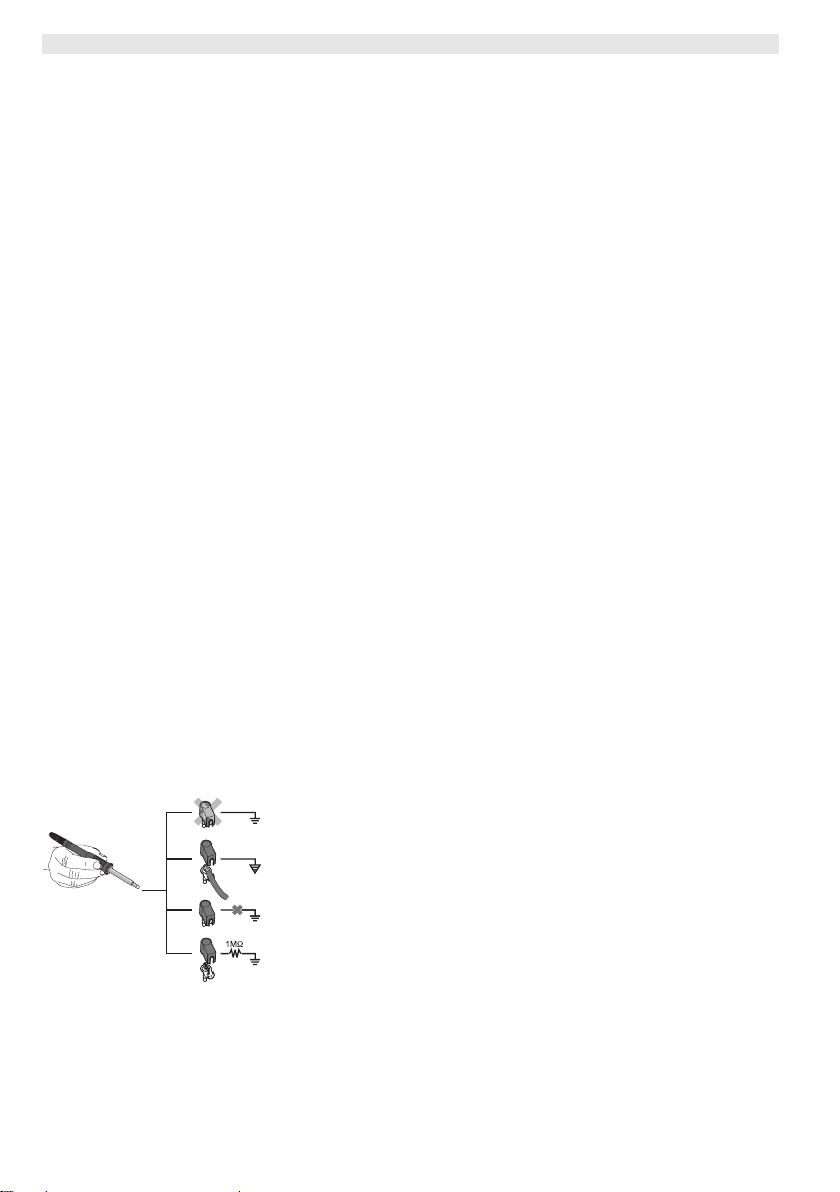
6-20 WX 2
Datos técnicos WX 2
Dimensiones L x An x Al (mm): 170 x 151 x 130
L x An x Al (pulgadas): 6,69 x 5,94 x
5,12
Peso aproximadamente 3,2 kg
Tensión de red 230 V, 50 Hz
Consumo de potencia 200 W (240 W)
Clase de protección I, caja antiestática
Protección Disparador de sobrecorriente T2 A
Rango de temperatura Regulable
50 °C – 550 °C (150 °F – 999 °F)
La gama de temperatura regulable
varía en función de la herramienta.
Precisión de la temperatura ± 9 °C (± 17 °F)
Estabilidad térmica ± 2 °C (± 4 °F)
Conexión equipotencial A través del conector hembra jack de
3,5 mm en la parte trasera del
aparato.
Material de la caja Base de aluminio
con recubrimiento antiestático negro
(AMS 70002); caja de poliamida
(PA), antiestática
Material del panel de
Cristal antiestático con recubrimiento
control
Panel de control,
74 x 38 mm
dimensiones
Resolución 255 x 127 (128) dots
Iluminación del fondo 4 LEDs
Fig. 3
Equipotencial
a
Gracias a las diferentes posibilidades de conexión del conector
hembra de 3,5 mm (14) hay 4 variantes posibles:
b
− (a) Toma de tierra directa: sin conector (estado de suministro).
− (b) Equipotencial: con conector, línea equipotencial en el contacto
c
d
central.
− (c) Sin potencial: con conector
− (d) Toma de tierra indirecta: con enchufe y resistencia soldada.
Puesta a tierra a través de la resistencia seleccionada
Puerto USB
La unidad de control WX 2 incorpora un puerto USB (10) en la parte
frontal para la actualización de firmware, parametrización y
monitorización. El puerto USB (10) es compatible con todas las
memorias portátiles USB convencionales.
Page 47
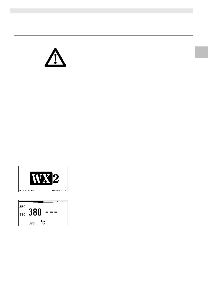
WX 2 7-20
¡ADVERTENCIA!
Fig. 4
Fig. 5
5 Puesta en servicio del aparato
Peligro de descarga eléctrica y de sufrir quemaduras
Si se conecta inadecuadamente la unidad de control existe
peligro de provocar daños personales y materiales como
consecuencia de descargas eléctricas. Durante el funcionamiento
de la unidad de control existe peligro de sufrir quemaduras con el
soldador.
Z Lea detenidamente todas las normas de seguridad adjuntas,
las normas de seguridad del manual de uso, así como las
instrucciones de su unidad de control antes de ponerla en
funcionamiento y siga siempre las normas de precaución.
Z Siempre y cuando no utilice el soldador colóquelo en el
soporte de seguridad.
Consulte los componentes del aparato (Fig. 1 y Fig. 2).
Nota En la estación de soldar WX 2 se pueden conectar únicamente
soldadores con los conectores adecuados.
Los utensilios que se pueden conectar a la estación WX 2 figuran
en la lista de accesorios de la página 19.
1. Desembalar el aparato cuidadosamente.
2. Conectar las herramientas de soldar como se indica a
continuación:
Introducir el conector macho del soldador en el conector hembra
(9/12) de la unidad de control y fijar su posición girándolo
ligeramente hacia la derecha.
3. Colocar el soldador en el soporte.
4. Comprobar si la tensión de la red coincide con la de la placa de
datos técnicos y si el interruptor principal (18) está
desconectado.
5. Conectar la unidad de control a la red (16).
6. Encender el aparato con el interruptor principal (18).
Aparecerá el indicador Startup en la pantalla (véase la Fig. 4).
Una vez conectado el aparato el microprocesador realiza un autotest y lee los parámetros guardados en la herramienta.
Si hay un soldador conectado aparecerá la temperatura ajustada
(valor de referencia, 30/26) en la pantalla, la unidad de medición de
la temperatura °C/°F (28), la temperatura real (temperatura actual
del soldador) (29) y las temperaturas fijas memorizadas
(33/32/23/24).
DE EN ES IT ES PT NL SV DK FI GR TR CZ PL HU SK SL EE LV LT
Page 48
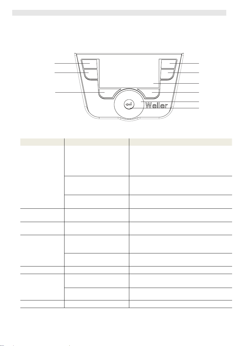
8-20 WX 2
6 Manejo del aparato
6.1 Manejo
2
1
13
Fig. 6: controles WX 2
Teclas Manejo Función
Tecla de mando 1, 2,
3, 4
Mantener pulsada la tecla 1, 2, 3 ó
Mantener pulsadas al mismo
Tecla 13 y 1
ó 2
Tecla 6 y 3
ó 4
Selector 6, 13 Pulsar brevemente la tecla 6 ó 13
Tecla 6 Pulsar brevemente la tecla 6
Selector giratorio 7 Mover el dedo sobre el selector
Hacer clic a la derecha o izquierda
Tecla Enter 8 Pulsar brevemente la tecla 8
*) véanse también los componentes del aparato (Fig. 1 y Fig. 2).
Pulsar brevemente la tecla 1, 2, 3
ó 4
4
durante 3 seg.
tiempo las teclas 1 y 2 ó 3 y 4
Mantener pulsadas al mismo
tiempo las teclas 13 y 1 ó 13 y 2
Mantener pulsadas al mismo
tiempo las teclas 6 y 3 ó 6 y 4
Mantener pulsada la tecla 6 ó 13
durante 3 seg.
giratorio
La temperatura fija (23/24/32/33)* queda guardada
como temperatura de referencia activa (26/30)*.
(canal de soldador: tecla 1, 2 = izquierdo;
Tecla 3, 4 = derecho)
− Avanzar/retroceder en el menú de parámetros
− La temperatura de referencia activa queda
memorizada como temperatura fija de la tecla
pulsada (1, 2, 3 ó 4).
− 1 y 2 = el canal izquierdo (12)* se bloquea o abre
− 3 y 4 = el canal derecho (9)* se bloquea o abre
− Acceso al Menú de parámetros
− Acceso al Menú de parámetros
− Selección del equipo adicional, requisito para abrir
los ajustes de los parámetros del equipo adicional (p.
ej. WFE)
− Se abrirá la ventana de la temperatura de referencia
− Saldrá del menú de parámetros
− Selección/Ajuste del valor
− Navegación por el menú
− Se abrirá la ventana de la temperatura de referencia
del soldador conectado a la derecha/izquierda
− Se confirma el valor/opción seleccionada
3
4
5
6
7
8
Page 49
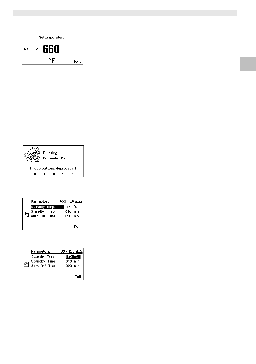
WX 2 9-20
Fig. 7
Fig. 8
Fig. 9
Fig. 10
6.2 Ejemplo de manejo 1:
Ajuste de la temperatura
1. Mantener pulsado el selector 6 ó 13
durante 3 seg.
La pantalla cambiará a la temperatura de referencia (véase la
Fig. 7).
2. Ajustar la temperatura de referencia deseada mediante el
selector giratorio (7).
3. Confirmar el valor pulsando la tecla Enter (8).
4. Salir del menú de parámetros pulsando la tecla 6.
Nota Si no hay actividad durante 10 segundos se sale automáticamente
del menú de parámetros.
6.3 Ejemplo de manejo 2:
Acceso al menú de parámetros y selección del
punto de menú
1. Mantener pulsadas al mismo tiempo las teclas 13 y 1 ó 13 y 2 ó 6
y 3 ó 6 y 4.
Mientras que el aparato pasa al menú de parámetros aparecerá
en la pantalla el siguiente mensaje de texto (véase también la
Fig. 8):
"Pasar al menú de parámetros" "Mantener pulsadas las teclas".
2. Seleccionar el punto de menú mediante el selector giratorio (7).
El punto seleccionado aparecerá sobre un fondo negro (p. ej.
"Standby Temp.“, véase la Fig. 9).
3. Confirmar el punto seleccionado pulsando la tecla Enter (8).
La pantalla pasará al Modo de Selección/Entrada (véase la
Fig. 10).
4. Realizar el ajuste con el selector giratorio (7).
5. Confirmar el ajuste pulsando la tecla (8).
El ajuste queda memorizado y la pantalla muestra el menú de
parámetros.
6. Seleccionar un nuevo punto de menú mediante el selector
giratorio (7) y ajustar el valor deseado (véase el apartado 3.-5.)
– o –
salir del menú de parámetros pulsando la tecla 6.
DE EN ES IT ES PT NL SV DK FI GR TR CZ PL HU SK SL EE LV LT
Page 50
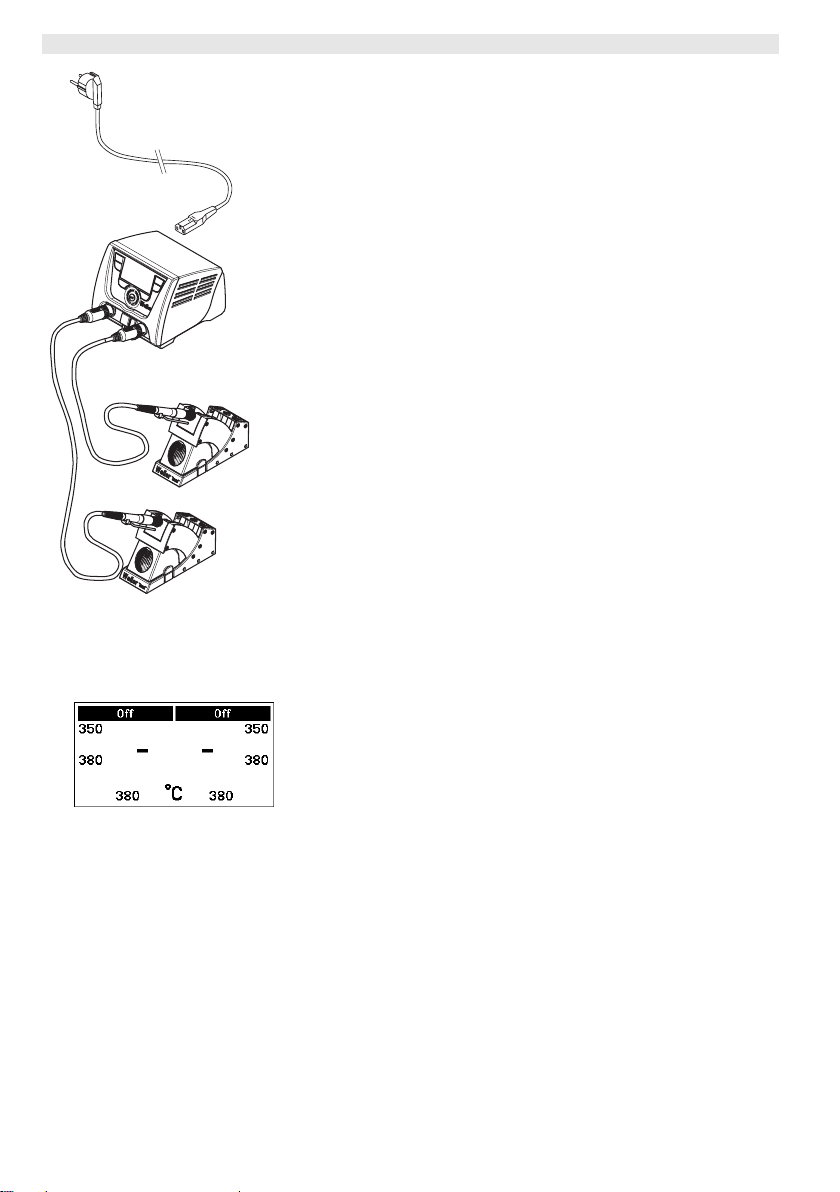
10-20 WX 2
6.4 Conexión del soldador
Consulte los componentes del aparato (Fig. 1 y Fig. 2).
1. Comprobar si el soldador deseado está conectado correctamente
(véase "Puesta en servicio del aparato" en la página 7).
2. Conectar el aparato con el interruptor principal (18).
La pantalla mostrará la temperatura real (29), la temperatura de
referencia (26/30) así como las temperaturas fijas (23/24 ó
32/33) del soldador conectado. La temperatura de referencia y
las temperaturas fijas están guardadas en el soldador. La
temperatura real aumentará hasta alcanzar la temperatura de
referencia (= el soldador se calienta).
Nota Si desea conectar dos soldadores al mismo tiempo en la estación
WX 2 deberá tener en consideración la desconexión por
sobrecarga.
Nota
Encontrará más variantes de conexión en la página 21.
Siga las instrucciones del manual de uso del aparato conectado.
Fig. 11: WX 2 con
soldador conectado
Fig. 12
Desconexión por sobrecarga (240 W)
Si conecta dos soldadores al mismo tiempo en la estación WX 2,
que juntos precisen más de 240 W, se producirá una desconexión
por sobrecarga (véase la Fig. 12).
En este caso sólo podrá usar un soldador/canal.
Activación del soldador/canal:
Z Pulsar al mismo tiempo las teclas de mando deseadas 1 y 2
(canal izquierdo (12)) o 3 y 4 (canal derecho (9)).
– o–
Retirar el soldador deseado de su soporte.
Page 51
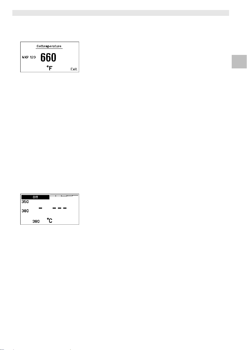
WX 2 11-20
Fig. 13
6.5 Ajuste individual de la temperatura
Consulte los componentes del aparato (Fig. 1 y Fig. 2).
Ajuste de la temperatura fija
1. Mantener pulsado el selector deseado 6 ó 13.
La temperatura de referencia actual aparecerá en la pantalla
(véase la Fig. 13).
2. Ajustar la temperatura de referencia deseada mediante el
selector giratorio (7).
3. Confirmar el valor pulsando la tecla Enter (8).
4. Mantener pulsado el selector 1, 2, 3 ó 4 durante 3 seg. para
guardar (memorizar) la temperatura de referencia actual como
temperatura fija (en la tecla pulsada).
Nota Encontrará más información (p. ej. temperatura fija, configuración
de fábrica) sobre el soldador inteligente en el manual de uso
correspondiente.
Selección de la temperatura con las teclas de mando 1, 2, 3 y 4
La temperatura de referencia se puede ajustar mediante la
selección de dos temperaturas (temperaturas fijas) preajustadas
(por cada soldador).
Z Pulsar la tecla de temperatura deseada 1, 2, 3 y 4.
El soldador se ajustará a la temperatura deseada.
6.6 Conexión/Desconexión del canal
Consulte los componentes del aparato (Fig. 1 y Fig. 2).
DE EN ES IT ES PT NL SV DK FI GR TR CZ PL HU SK SL EE LV LT
Fig. 14
Canal izquierdo (12)
Z Pulsar al mismo tiempo las teclas de mando 1 y 2 para
conectar/desconectar el soldador.
Canal derecho (9)
Z Pulsar al mismo tiempo las teclas de mando 3 y 4 para
conectar/desconectar el soldador.
Nota El soldador se conectará en cuanto que sea retirado del soporte.
Los soldadores incorporan un sensor de movimiento.
Canal bloqueado
Si un canal está bloqueado aparecerá "OFF" en la pantalla (19).
Page 52

12-20 WX 2
6.7 Soldar y desoldar
Z Realice los trabajos de soldadura según el manual de uso del
soldador conectado.
Manipulación de las puntas de soldar
− Al calentar por primera vez la punta de soltar seleccionada
aplicarle un poco de estaño. De esta forma se eliminan posibles
restos de óxido o impurezas que pueden aparecer durante su
almacenaje.
− Para realizar descansos mientras suelda o al colocar el soldador
en el soporte es imprescindible procurar que la punta de soldar
esté bien estañada.
− No utilizar fundentes agresivos.
− Asegurarse de que las puntas de soltar estén siempre colocadas
correctamente.
− Ajustar la temperatura más baja posible
− Seleccionar la punta de soldar más grande posible para la
aplicación deseada, por regla general: aprox. tan grande como el
punto de soldadura.
− Procurar que el calor se transmita ampliamente entre la punta de
soldar y el punto de soldadura estañando bien la punta de soldar.
− En caso de pausas prolongadas desconectar el equipo y utilizar la
función de reducción de la temperatura de la estación Weller.
− Aplicar estaño a la punta de soldar antes de depositar el soldador
durante un espacio de tiempo prolongado.
− Aplicar el estaño directamente en el punto de soldadura para que
se funda y no en la punta de soldar.
− Cambiar las puntas de soldar con las herramientas apropiadas.
− No someter la punta de soldar a esfuerzos mecánicos.
Nota Las unidades de control están ajustadas para funcionar con puntas
de soldar de tamaño mediano. Pueden surgir diferencias de
comportamiento debido al cambio de punta o al utilizar puntas con
una forma diferente.
Page 53
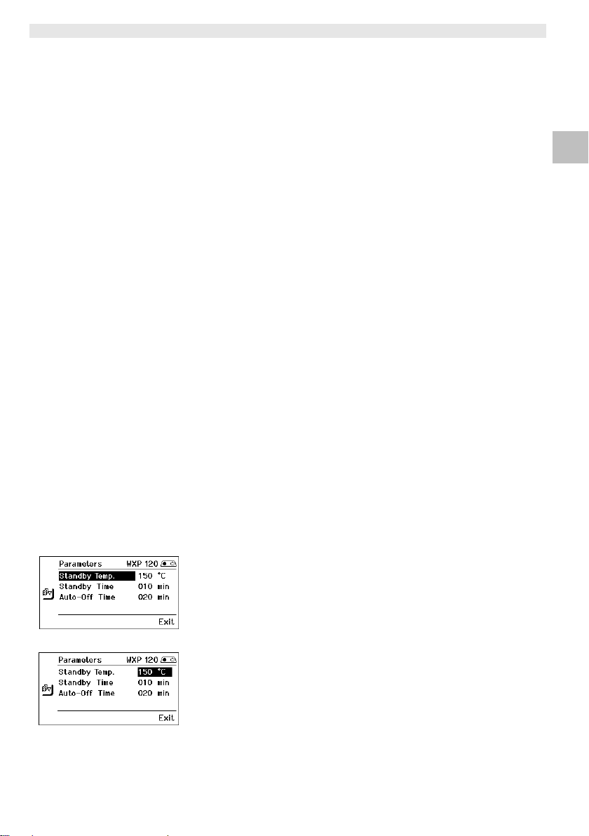
WX 2 13-20
7 Ajuste de los parámetros a través del
menú de parámetros
El menú de parámetros está dividido en dos:
Parámetros
Opciones:
- Temperatura standby
- Tiempo standby (desconexión de la temperatura)
- Tiempo AUTO-OFF (tiempo de desconexión automática)
- Offset (offset de temperatura)
- Comportamiento térmico
- Rango de proceso
Parámetros de la estación
Opciones:
- Idioma
- Unidad de medición de la temperatura °C/°F
- Contraseña (función de bloqueo)
- Activación/desactivación de tonos del teclado
- Contraste LCD
- Brillo LCD
- Salvapantalla
7.1 Ajuste de los parámetros
Consulte los componentes del aparato (Fig. 1 y Fig. 2).
DE EN ES IT ES PT NL SV DK FI GR TR CZ PL HU SK SL EE LV LT
Fig. 15
Fig. 16
Ajuste de la temperatura standby
Nota Los soldadores disponen de un detector de uso (sensor) en el
mango que en caso de inactividad se encarga de iniciar
automáticamente la operación de enfriamiento.
Encontrará más información sobre el soldador inteligente en el
manual de uso correspondiente.
Después de una desconexión de temperatura se ajusta
automáticamente la temperatura standby.
1. Acceder al menú de parámetros.
2. Seleccionar el punto de menú Temperatura standby.
3. Ajustar la temperatura standby mediante el selector giratorio (7).
4. Confirmar el valor pulsando la tecla Enter (8).
5. Salir del menú de parámetros pulsando la tecla 6.
Page 54
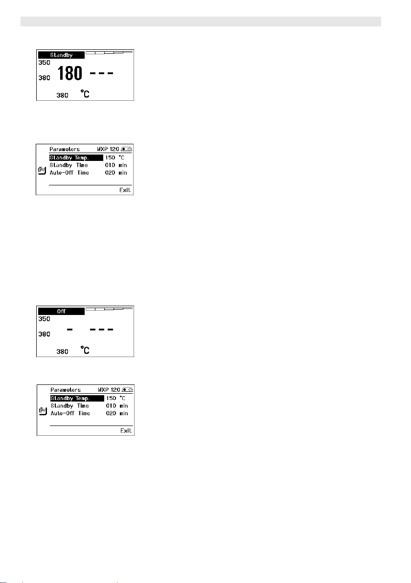
14-20 WX 2
Ajuste de la desconexión de la temperatura (Tiempo standby)
Cuando no se utiliza el soldador, la temperatura se reduce hasta
alcanzar la temperatura standby después de que haya transcurrido
el tiempo standby ajustado. El estado standby se indica con un valor
real intermitente y en la pantalla aparece "Standby" (20).
Fig. 17
Fig. 18
Fig. 19
Fig. 20
Al pulsar la tecla de mando 1, 2, 3 ó 4 finaliza este estado standby.
El sensor integrado en el soldador detectar el cambio de estado y
desactiva el estado standby en cuando que se mueve el soldador.
Ajuste del tiempo standby:
1. Acceder al menú de parámetros.
2. Seleccionar el punto de menú Tiempo standby y confirmar.
3. Ajustar el tiempo standby deseado mediante el selector
giratorio (7).
En Tiempo stanby están disponibles los siguientes ajustes:
− "OFF" = "0 min": el tiempo standby está desconectado
(configuración de fábrica)
− "ON" = "1-99 min": tiempo standby, ajustable individualmente
4. Confirmar el valor pulsando la tecla Enter (8).
Seleccionar otro parámetro ajustable en el menú
o
salir del menú de parámetros pulsando la tecla 6.
Nota En los trabajos de soldar que requieran poca temperatura se puede
ver mermada la fiabilidad de la función standby.
Ajustar el tiempo de desconexión automática (AUTO-OFF)
Si no se utiliza el soldador, una vez transcurrido el
tiempo AUTO-OFF se desconecta la resistencia del soldador.
La desconexión de temperatura se realiza independientemente de la
función standby ajustada. La temperatura real parpadea y sirve para
indicar el calor residual. Mientras aparece en la pantalla "OFF" (19).
1. Acceder al menú de parámetros.
2. Seleccionar el punto de menú Tiempo AUTO-OFF y confirmar.
3. Ajustar el tiempo AUTO-OFF deseado mediante el selector
giratorio (7).
En tiempo AUTO-OFF están disponibles los siguientes ajustes:
− "OFF" = "0 min": la función AUTO-OFF está desconectada
(configuración de fábrica)
− "ON" = "1-999 min": tiempo AUTO-OFF, ajustable
individualmente.
4. Confirmar el espacio de tiempo mediante la tecla Enter (8).
Seleccionar otro parámetro ajustable en el menú o
salir del menú de parámetros pulsando la tecla 6.
Nota Reset del modo standby y AUTO-OFF:
Se efectúa sin soporte de seguridad pulsando la tecla de mando
2, 3 ó 4 o retirando el soldador de
l soporte.
1,
Page 55
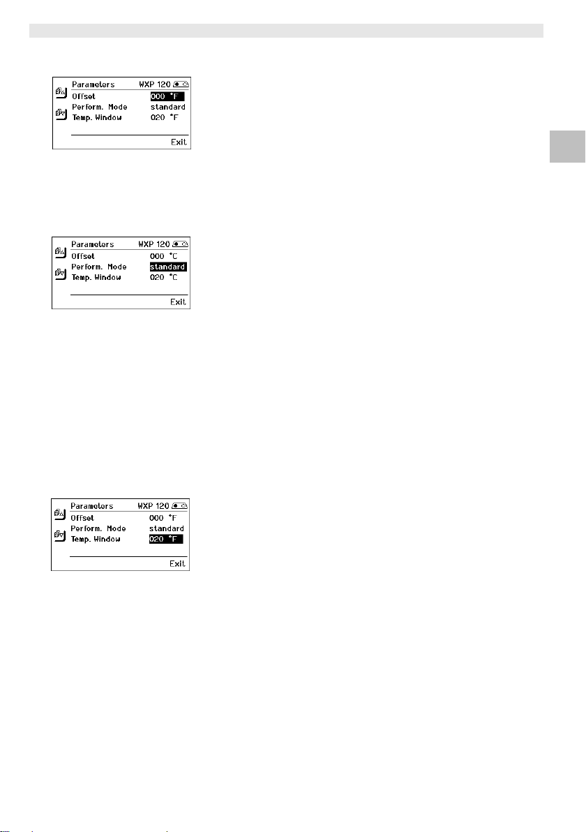
WX 2 15-20
Fig. 21
Fig. 22
Ajustar el offset de temperatura
La temperatura real de la punta del soldador se puede ajustar
introduciendo un offset de temperatura de aproximadamente ± 40
°C (± 72 °F).
1. Acceder al menú de parámetros.
2. Seleccionar el punto de menú OFFSET y confirmar.
3. Ajustar la temperatura OFFSET deseada mediante el selector
giratorio (7).
4. Confirmar el valor pulsando la tecla Enter (8).
Seleccionar otro parámetro ajustable en el menú o
salir del menú de parámetros pulsando la tecla 6.
Ajuste del comportamiento térmico
Esta función determina el comportamiento térmico del soldador
hasta alcanzar la temperatura ajustada.
1. Acceder al menú de parámetros.
2. Seleccionar el punto de menú comportamiento térmico y
confirmar.
3. Ajustar la función reguladora mediante el selector giratorio (7).
Dispone de los siguientes ajustes:
− "standard": calentamiento adaptado (medio) (configuración de
fábrica)
− "suave“: calentamiento lento
− "rápido“: calentamiento rápido
4. Confirmar el ajuste pulsando la tecla (8).
Seleccionar otro parámetro ajustable en el menú o
salir del menú de parámetros pulsando la tecla 6.
DE EN ES IT ES PT NL SV DK FI GR TR CZ PL HU SK SL EE LV LT
Fig. 23
Ajuste del rango de proceso
El margen de temperatura ajustado en el rango de proceso
determina el comportamiento de las señales de la salida de
conexión sin potencial.
1. Acceder al menú de parámetros.
2. Seleccionar el punto de menú Rango de proceso y confirmar.
3. Ajustar el margen de temperatura deseado en el rango de
proceso mediante el selector giratorio (7).
4. Confirmar el valor pulsando la tecla Enter (8).
Seleccionar otro parámetro ajustable en el menú o
salir del menú de parámetros pulsando la tecla 6.
Nota En soldadores con iluminación LED (p. ej. WXP 120) el margen de
proceso determina el comportamiento de la iluminación LED.
− Si la luz está encendida constantemente significa que se ha
alcanzado la temperatura deseada o que la temperatura está
dentro del rango de proceso predefinido.
− La luz intermitente significa que el sistema se está calentando y
que la temperatura está fuera del rango de proceso.
Page 56
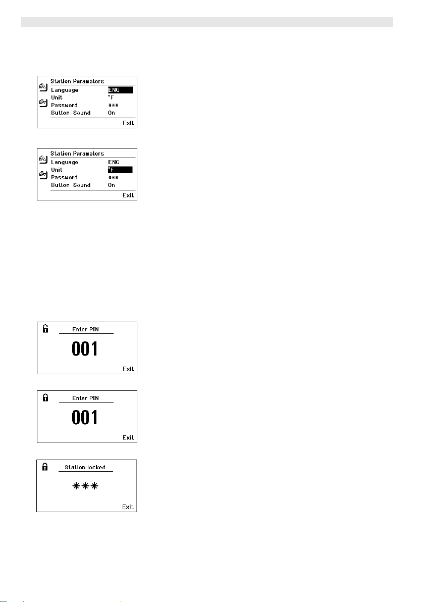
16-20 WX 2
7.2 Ajuste de los parámetros de la estación
Consulte los componentes del aparato (Fig. 1 y Fig. 2).
Selección del idioma del menú
1. Acceder al menú de parámetros.
2. Seleccionar el punto de menú Idioma y confirmar.
3. Ajustar el idioma deseado mediante el selector giratorio (7).
Fig. 24
Fig. 25
4. Confirmar el ajuste pulsando la tecla Enter (8).
Cambio de la unidad de medición de la temperatura
1. Acceder al menú de parámetros.
2. Seleccionar el punto de menú Unidad de medición temperatura
°C/°F y confirmar.
3. Ajustar la unidad de medición deseada para la temperatura
mediante el selector giratorio (7).
4. Confirmar el ajuste pulsando la tecla (8).
Activar/desactivar la función de bloqueo
Tras conectar el bloqueo, en la estación de soldar tan sólo se
pueden manejar las teclas de la temperatura fija (= teclas de mando
1, 2, 3 y 4) . No es posible cambiar ninguno de los demás ajustes
hasta que se realice el desbloqueo.
Nota Si realmente desea disponer únicamente de una temperatura
deberá ajustar las teclas de mando 1, 2 y/o 3, 4 (teclas de
temperatura fija) a la misma temperatura.
Fig. 26
Fig. 27
Fig. 28
Bloqueo de la estación de soldar:
1. Acceder al menú de parámetros.
2. Seleccionar el punto de menú Contraseña y confirmar.
3. Ajustar el código de bloqueo deseado con tres dígitos
(entre 001-999) mediante el selector giratorio (7) (véase la
Fig. 26).
4. Confirmar el valor pulsando la tecla Enter (8).
El bloqueo está activado (en la pantalla aparecerá un candado (27),
véase también la Fig. 27).
Desbloqueo de la estación de soldar
1. Acceder al menú de parámetros.
Si el bloqueo está activado se abrirá automáticamente el punto
del menú Contraseña. En la pantalla aparecerán tres asteriscos
(***).
2. Introducir el código de bloqueo mediante el selector giratorio (7).
3. Confirmar el código con la tecla Enter (8).
Page 57
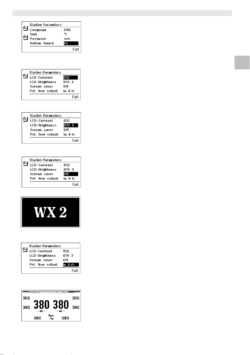
WX 2 17-20
Fig. 29
Fig. 30
Fig. 31
Fig. 32
Activación/desactivación de los tonos del teclado.
1. Acceder al menú de parámetros.
2. Seleccionar el punto de menú Tonos teclado y confirmar.
3. Activar o desactivar los tonos del teclado mediante el selector
giratorio (7).
4. Confirmar el ajuste pulsando la tecla (8).
Ajuste del contraste LCD
1. Acceder al menú de parámetros.
2. Seleccionar el punto de menú Contraste LCD y confirmar.
3. Ajustar el contraste deseado en la pantalla LCD mediante el
selector giratorio (7).
4. Confirmar el ajuste pulsando la tecla Enter (8).
Ajuste del brillo LCD
1. Acceder al menú de parámetros.
2. Seleccionar el punto de menú Brillo LCD y confirmar.
3. Ajustar el brillo deseado en la pantalla LCD mediante el selector
giratorio (7).
4. Confirmar el ajuste pulsando la tecla Enter (8).
Ajuste del salvapantalla
1. Acceder al menú de parámetros.
2. Seleccionar el punto de menú Salvapantalla y confirmar.
3. Activar o desactivar el salvapantalla mediante el selector
giratorio (7).
4. Confirmar el ajuste pulsando la tecla Enter (8).
DE EN ES IT ES PT NL SV DK FI GR TR CZ PL HU SK SL EE LV LT
Fig. 33
Fig. 34
Fig. 35
Definición de la salid del robot
La salida para el robot se encuentra en la parte trasera del aparato
(15). La asignación de los pines de la salida del robot se puede
consultar en la página 21. En la configuración original el canal
izquierdo del soldador está asignado a la salida del robot. No
obstante, esta asignación se puede cambiar.
1. Acceder al menú de parámetros.
2. Seleccionar el punto de menú Salida de robot y confirmar.
3. Seleccionar el canal/canales mediante el selector giratorio (7).
En Salida del robot están disponibles los siguientes ajustes:
− "izquierdo“: canal izquierdo (configuración de fábrica)
− "derecho“: canal derecho
− "izquierdo & derecho“: ambos canales
4. Confirmar el ajuste pulsando la tecla (8).
Page 58
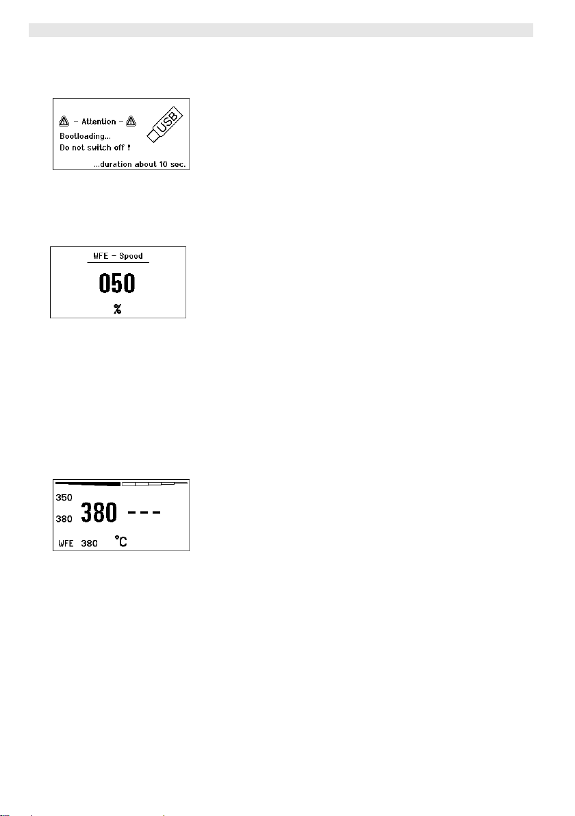
18-20 WX 2
Nota Una vez alcanzada la temperatura de trabajo del robot aparecerá
en la pantalla un – ok - (véase la Fig. 34).
7.3 Actualización de firmware
1. Desconectar la estación de soldar WX 2.
2. Introducir la memoria portátil (lápiz USB) en el puerto USB.
Fig. 36
3. Conectar la estación de soldar WX 2.
El firmware se actualiza automáticamente (véase la Fig. 35).
Si ya tuviera instalado un firmware actualizado, éste no sufrirá
ninguna modificación.
Nota Mientras se actualiza el firmware no está permitido desconectar la
estación.
7.4 Conexión de equipos adicionales
Consulte los componentes del aparato (Fig. 1 y Fig. 2).
Fig. 37
Los equipos adicionales se pueden conectar en la interfaz de la
parte delantera (11) y/o en la interfaz de la parte trasera (15) de la
estación de soldar WX 2.
La estación de soldar WX 2 detecta automáticamente el equipo que
está conectado. La estación de soldar WX 2 muestra en la parte
izquierda (interfaz delantera (11), véase la Fig. 36) o en la parte
derecha (interfaz trasera) el símbolo o el nombre del equipo
adicional conectado (31/25).
Fig. 38: conexión
delantera de WFE
7.5 Ajuste de los parámetros de los equipos
adicionales
Consulte los componentes del aparato (Fig. 1 y Fig. 2).
1. Seleccionar un equipo adicional mediante la tecla de equipo
adicional (delante/detrás) (6, 13).
El parámetro ajustable aparecerá en la pantalla (p. ej. número de
revoluciones).
2. Ajustar el valor deseado mediante el selector giratorio (7).
3. Confirmar el valor pulsando la tecla Enter (8).
o
Pulsar la tecla 6 para salir.
Page 59

WX 2 19-20
8 Cuidado y mantenimiento de la estación
WX 2
Z Si estuviera sucio, limpiar el panel de control con un paño
adecuado.
Z Cerrar las interfaces no utilizadas con sus tapas.
9 Mensajes de error y su reparación
Mensaje/Síntoma Causa posible Reparación
Indicación "- - -"
Sin función de pantalla
(pantalla desconectada)
OFF
No se puede conectar el canal
− No se ha detectado la
herramienta
− Herramienta defectuosa
− No hay tensión de red
disponible
− Desconexión por sobrecarga − Únicamente se puede usar un
− Comprobar la conexión de la
herramienta al aparato
− Comprobar la herramienta
conectada
− Conectar el interruptor principal
− Comprobar la tensión de red
− Comprobar el fusible del aparato
soldador.
10 Accesorios
T005 29 202 99 WXP 120 Kit de soldadura con soporte WDH 10
T005 29 206 99 WXP 200 Kit de soldadura con soporte WDH 31
T005 13 178 99 WXMT Micropinza de desoldar con soporte
WDH 60
T005 29 204 99 WXMP Microsoldador con soporte WDH 50
T005 15 121 99 WDH 10 Soporte de seguridad para WXP 120
T005 15 158 98 WDH 31 Soporte de seguridad para WXP 200
T005 15 156 99 WDH 50 Soporte de seguridad para WXMP
T005 15 169 99 WDH 60 Soporte de seguridad para WXMT
T005 36 476 99 WFE 20D Aspirador de humo de soldadura 230 V
T005 36 266 99 WFE 2S Aspirador portátil 230 V
T005 36 256 99 WFE 4S Aspirador portátil 230 V
T005 36 586 99 WFE 8S Aspirador portátil 230 V
T005 33 648 99 WHP 1000 Placa precalefactora 1000 W
T005 33 386 99 WHP 3000 Placa precalefactora por infrarrojos
600 W
T005 33 646 99 WHP 3000 Placa precalefactora por infrarrojos
1200 W
T005 87 647 10 WX Cable de conexión
T005 87 647 11 WX Adaptador para PC
T005 87 647 12 WX Adaptador para WFE/WHP
DE EN ES IT ES PT NL SV DK FI GR TR CZ PL HU SK SL EE LV LT
Page 60

20-20 WX 2
Consultar el resto de los accesorios en los manuales de uso de los
diferentes kits de accesorios para soldador.
11 Eliminación de residuos
Elimine los componentes y filtros cambiados en el aparato, así como
aparatos en desuso, siguiendo la normativa vigente en su país.
12 Garantía
Los derechos de reclamación por defectos del comprador prescriben
un año después de la compra. Sólo válido para los derechos del
comprador según el art. §§ 478, 479 BGB (código civil alemán).
Únicamente nos responsabilizamos de los derechos de garantía
cuando la garantía de compra y vida útil del aparato haya sido
entregada por nosotros por escrito y utilizando el término "Garantía".
¡Reservado el derecho a realizar modificaciones técnicas!
Encontrará los manuales de instrucciones actualizados en
www.weller.eu.
Page 61
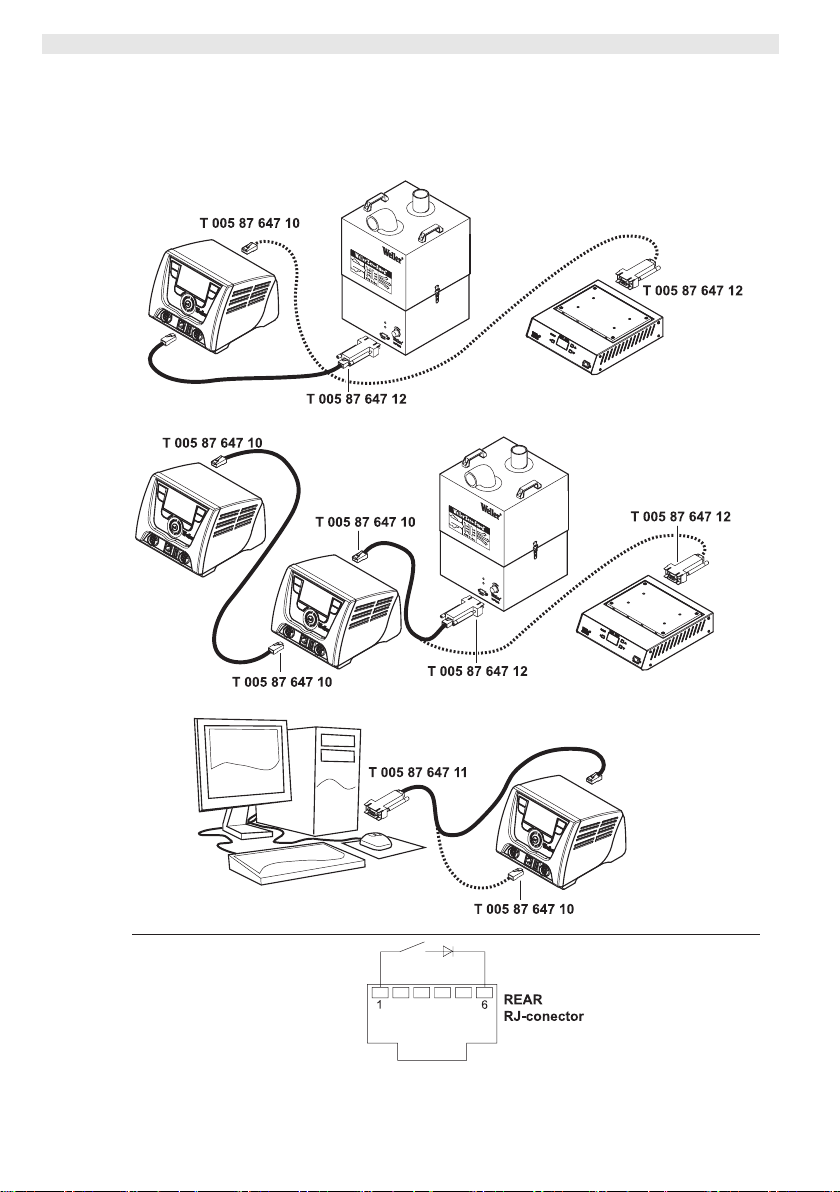
WX 2 Alternative configurations
Alternative configurations
DE EN FR IT ES PT NL SV DK FI GR TR CZ PL HU SK SL EE LV LT
Robot output pin assignments
Page 62
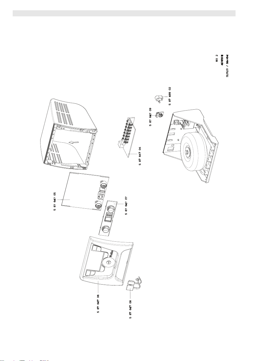
WX 2 Exploded Drawing
Exploded-view diagram
Note Components must be fitted and replaced by the authorised Repair
Service, otherwise the warranty will be void.
Gedruckt durch: Martinu am: 31.5.2010
Page 63

Page 64

GERMANY
A
Cooper Tools GmbH
A company of Apex Tool
Group, LLC.
Carl-Benz-Str. 2
74354 Besigheim
Phone: +49 (0) 7143 580-0
Fax: +49 (0) 7143 580-108
GREAT BRITAIN
Cooper Tools
A company of Apex Tool
Group, LLC.
A Division of Cooper (GB) Ltd.
4th Floor Pennine House
Washington, Tyne & Wear
NE37 1LY
FRANCE
Cooper Tools S.A.S.
A company of Apex Tool
Group, LLC.
25 Rue Maurice Chevalier BP 46
77832 Ozoir-la-Ferrière Cedex
Phone: +33 (01) 60.18.55.40
Fax: +33 (01) 64.40.33.05
Phone: +44 (0191) 419 7700
Fax: +44 (0191) 417 9421
ITALY
Cooper Italia S.r.I.
A company of Apex Tool
Group, LLC.
Viale Europa 80
20090 Cusago (MI)
Phone: +39 (02) 9033101
Fax: +39 (02) 90394231
SWITZERLAND
Erem Sàrl
A company of Apex Tool
Group, LLC.
Rue de la Roselière 12
1400 Yverdon-les-Bains
Phone: +41 (024) 426 12 06
Fax: +41 (024) 425 09 77
USTRALIA
Cooper Tools
A company of Apex Tool
Group, LLC.
P.O. Box 366
519 Nurigong Street
Albury, N. S. W. 2640
Phone: +61 (2) 6058-0300
Fax: +61 (2) 6021-7403
CANADA
Cooper Hand Tools
A company of Apex Tool
Group, LLC.
164 Innisfil
Barrie Ontario
Canada L4N 3E7
Phone: +1 (705) 728 5564
Fax: +1 (705) 728 3406
CHINA
Cooper Hand Tools
A company of Apex Tool
Group, LLC.
18th Floor, Yu An Building
738 Dongfang Road
Pudong, Shanghai
200122 China
Phone: +86 (21) 5111-8300
Fax: +86 (21) 5111-8446
USA
Cooper Tools
A company of Apex Tool
Group, LLC.
P.O. Box 728
Apex, NC 27502-0728
North-East
Phone: +1 (919) 362-7540
Fax: +1 (800) 854-5137
West Coast (South-West)
Phone: +1 (919) 362-1709
Fax: +1 (800) 846-7312
All other USA inquires
South
Phone: +1 (919) 362-7541
Fax: +1 (800) 854-5139
Midwest
Phone: +1 (919) 362-7542
Fax: +1 (800) 854-5138
Fax: +1 (800) 423-6175
www.weller.eu
www.apextoolgroup.eu
Weller® is a registered Trademark and registered Design of Apex Tool Group, LLC.
© 2010, Apex Tool Group, LLC.
T005 57 215 00 / 09.2010
 Loading...